EP0911007B1 - Elévateur pour fauteuil roulant - Google Patents
Elévateur pour fauteuil roulant Download PDFInfo
- Publication number
- EP0911007B1 EP0911007B1 EP98120804A EP98120804A EP0911007B1 EP 0911007 B1 EP0911007 B1 EP 0911007B1 EP 98120804 A EP98120804 A EP 98120804A EP 98120804 A EP98120804 A EP 98120804A EP 0911007 B1 EP0911007 B1 EP 0911007B1
- Authority
- EP
- European Patent Office
- Prior art keywords
- platform structure
- bridge plate
- wheelchair lift
- lift
- platform
- Prior art date
- Legal status (The legal status is an assumption and is not a legal conclusion. Google has not performed a legal analysis and makes no representation as to the accuracy of the status listed.)
- Expired - Lifetime
Links
- 230000033001 locomotion Effects 0.000 claims description 55
- 230000007246 mechanism Effects 0.000 claims description 31
- 239000012530 fluid Substances 0.000 description 19
- 230000004888 barrier function Effects 0.000 description 3
- 235000001674 Agaricus brunnescens Nutrition 0.000 description 2
- 230000008901 benefit Effects 0.000 description 2
- 150000001875 compounds Chemical class 0.000 description 2
- 230000001276 controlling effect Effects 0.000 description 2
- 230000002079 cooperative effect Effects 0.000 description 2
- 230000006378 damage Effects 0.000 description 2
- 208000027418 Wounds and injury Diseases 0.000 description 1
- 230000009471 action Effects 0.000 description 1
- XAGFODPZIPBFFR-UHFFFAOYSA-N aluminium Chemical compound [Al] XAGFODPZIPBFFR-UHFFFAOYSA-N 0.000 description 1
- 229910052782 aluminium Inorganic materials 0.000 description 1
- 230000000712 assembly Effects 0.000 description 1
- 238000000429 assembly Methods 0.000 description 1
- 238000005452 bending Methods 0.000 description 1
- 230000002457 bidirectional effect Effects 0.000 description 1
- 239000002131 composite material Substances 0.000 description 1
- 238000010276 construction Methods 0.000 description 1
- 238000010586 diagram Methods 0.000 description 1
- 238000006073 displacement reaction Methods 0.000 description 1
- 230000000694 effects Effects 0.000 description 1
- 230000005484 gravity Effects 0.000 description 1
- 208000014674 injury Diseases 0.000 description 1
- 239000000463 material Substances 0.000 description 1
- 230000013011 mating Effects 0.000 description 1
- 230000009467 reduction Effects 0.000 description 1
Images



Classifications
-
- B—PERFORMING OPERATIONS; TRANSPORTING
- B60—VEHICLES IN GENERAL
- B60P—VEHICLES ADAPTED FOR LOAD TRANSPORTATION OR TO TRANSPORT, TO CARRY, OR TO COMPRISE SPECIAL LOADS OR OBJECTS
- B60P1/00—Vehicles predominantly for transporting loads and modified to facilitate loading, consolidating the load, or unloading
- B60P1/44—Vehicles predominantly for transporting loads and modified to facilitate loading, consolidating the load, or unloading having a loading platform thereon raising the load to the level of the load-transporting element
- B60P1/4471—General means for controlling movements of the loading platform, e.g. hydraulic systems
-
- A—HUMAN NECESSITIES
- A61—MEDICAL OR VETERINARY SCIENCE; HYGIENE
- A61G—TRANSPORT, PERSONAL CONVEYANCES, OR ACCOMMODATION SPECIALLY ADAPTED FOR PATIENTS OR DISABLED PERSONS; OPERATING TABLES OR CHAIRS; CHAIRS FOR DENTISTRY; FUNERAL DEVICES
- A61G3/00—Ambulance aspects of vehicles; Vehicles with special provisions for transporting patients or disabled persons, or their personal conveyances, e.g. for facilitating access of, or for loading, wheelchairs
- A61G3/02—Loading or unloading personal conveyances; Facilitating access of patients or disabled persons to, or exit from, vehicles
- A61G3/06—Transfer using ramps, lifts or the like
- A61G3/062—Transfer using ramps, lifts or the like using lifts connected to the vehicle
-
- Y—GENERAL TAGGING OF NEW TECHNOLOGICAL DEVELOPMENTS; GENERAL TAGGING OF CROSS-SECTIONAL TECHNOLOGIES SPANNING OVER SEVERAL SECTIONS OF THE IPC; TECHNICAL SUBJECTS COVERED BY FORMER USPC CROSS-REFERENCE ART COLLECTIONS [XRACs] AND DIGESTS
- Y10—TECHNICAL SUBJECTS COVERED BY FORMER USPC
- Y10S—TECHNICAL SUBJECTS COVERED BY FORMER USPC CROSS-REFERENCE ART COLLECTIONS [XRACs] AND DIGESTS
- Y10S414/00—Material or article handling
- Y10S414/13—Handlers utilizing parallel links
-
- Y—GENERAL TAGGING OF NEW TECHNOLOGICAL DEVELOPMENTS; GENERAL TAGGING OF CROSS-SECTIONAL TECHNOLOGIES SPANNING OVER SEVERAL SECTIONS OF THE IPC; TECHNICAL SUBJECTS COVERED BY FORMER USPC CROSS-REFERENCE ART COLLECTIONS [XRACs] AND DIGESTS
- Y10—TECHNICAL SUBJECTS COVERED BY FORMER USPC
- Y10S—TECHNICAL SUBJECTS COVERED BY FORMER USPC CROSS-REFERENCE ART COLLECTIONS [XRACs] AND DIGESTS
- Y10S414/00—Material or article handling
- Y10S414/134—Handicapped person handling
Definitions
- This invention relates to wheelchair lifts for vehicles, of a kind in which a platform structure for carrying the wheelchair is mounted on a pivotal mechanism which is attachable to the vehicle and which is selectively operable to move the platform structure between at least an entry position and a stowed position, and a bridge plate is pivotally attached to the platform structure for bridging a gap between the platform structure and the vehicle in the entry position.
- a wheelchair lift of this above-specified kind is known from WO-A-9214431, and involves a wheelchair-platform structure which comprises two platform parts.
- the outer of the two parts is pivoted upwardly from the inner, fixed part when the lift is stowed in a storage compartment below the passenger floor of a vehicle, and a hydraulic actuator carried by the inner part is used to pivot the outer part down into alignment with the inner part when the platform is to be deployed, and then up when it is to be stowed again.
- a wheelchair lift of the said above-specified kind is characterised in that the bridge plate is adapted such that when the platform structure is in the stowed position it is effectively locked in that position via the bridge plate.
- the wheelchair lift of the present invention has the advantage over the known lift of utilising the bridge plate to establish an effective lock on the platform structure that may be utilised to hold it in the stowed position.
- a selectively-releasable locking mechanism for attachment to the vehicle may be operative to block movement of the bridge plate, and thereby of the platform structure, when the platform structure is in its stowed position.
- the locking mechanism may be held in its operative condition by resilient restraint, and means may then be provided for selectively deflecting the resilient restraint such as to release the locking mechanism from its operative condition and thereby enable the platform structure to move.
- the bridge plate of the invention may have a lock-block for entering a well defined in a base attached to the vehicle, when the platform structure moves into the stowed position.
- the lock-block which may be carried on the underside of the bridge plate, may be obstructed in movement within the well by a part of a crank mechanism.
- the crank mechanism may be acted on by a spring for resiliently biasing it into a position in which said part provides the obstruction.
- a solenoid may be provided for selectively deflecting the spring and thereby redirecting the resilient bias such as to move said part into a position in which movement of the lock-block within the well is substantially unobstructed.
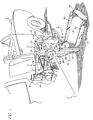
- FIGURE 1 a side portion of a vehicle V is shown carrying a wheelchair lift L for raising a passenger in a wheelchair (not shown) from ground level to a position for entering or leaving the vehicle V.
- the wheelchair lift L may be secured to the rear, side or other appropriate opening of a vehicle.
- the wheelchair lift L is installed at the floor F of the vehicle V to operate through a side doorway D.
- the lift L incorporates: a mobile platform 12 (lower right) for receiving a load such as a passenger in a wheelchair (not shown).
- a hydraulic system 14 (upper left) drives the platform through a parallelogram mechanism 13 as commanded by a control unit 16.
- the parallelogram mechanism 13 actuates the platform 12 in two different motion patterns, i.e., a passenger transporting, horizontal pattern with “raise” and “lower” phases, and a storage motion pattern with “store” (swing up) and “deploy” (swing down) phases.
- a passenger transporting, horizontal pattern with “raise” and “lower” phases and a storage motion pattern with "store” (swing up) and “deploy” (swing down) phases.
- the lift is locked against devious motions that could cause annoyance, damage or personal injury.
- the platform is locked in the stowed position to avoid drift that might occur.
- cooperating parallelogram structures of the mechanisms are interlocked.
- the platform 12 defines a generally rectangular, flat surface 15 that is pivotally connected to the vehicle V through the parallelogram mechanism 13.
- the parallelogram mechanism 13 includes two sets of parallelogram structures, an upper set being larger than a smaller set. Specifically, components of the mechanism form upper, laterally spaced parallelogram structures 17 and lower parallelogram structures 19 (smaller).
- the cooperating pairs of links 22 and 24 each are pivotally connected to a vertical channel arm 27.
- the upper ends 25 of the arms 27 are angled to extend offset from the vertical as illustrated.
- the offset ends 25, with the links 22 and 24, form three sides of the upper parallelogram structures 17.
- a pair of armature brackets 28 are pivotally connected to the links 22 and 24.
- a pair of panels 26 are mounted on the channel arms 27, illustrated only in FIGURE 1.
- the pivotally swinging parallelogram structures 17 are defined.
- a hydraulic ram or cylinder 38 operates in each of the upper parallelogram structures 17 to open and close the parallelogram (see FIGURE 2).
- the lower parallelogram structures 19 retain an open configuration during the transporting raise-lower motion pattern, but collapse or close during the storage motion pattern as a result of forceful engagement with the upper parallelogram structure 17.
- an interlock is provided between the parallelogram structures 17 and 19 during the storage motion pattern.
- the bridge plate 34 performs several functions, specifically, bridge, roll stop and latch.
- the bridge plate 34 is moved by the upper parallelogram structures 17 as a result of displacement of compound cams 35 (FIGURE 1, adjacent end 25, shown in phantom). As described below, the cams 35 position the bridge plate 34 through a cable connection.
- the bridge plate 34 latches the platform 12 to the vehicle floor F through the base 33 (FIGURE 1) rigidly affixed near the bottom of the doorway D.
- the rectangular well or recess 41 in the base 33 engagingly receives a latch member carried on the underside of the bridge plate 34 as described below.
- a release mechanism is mounted on the armature bracket 28 (FIGURE 1) to release the latch.
- the bridge plate 34 is raised as a roll stop or barrier to confine the transported wheelchair.
- elongated side risers or guide rails 30 (lower right) are fixed on each side of the platform 12.
- a pivotal roll stop or end flap 32 is fixed adjacent to the surface 15.
- the flap 32 rotates from a somewhat horizontal ramp position to a vertical barrier or roll stop position.
- Various mechanisms are known for positioning the end flap 32, depending on the location of the platform 12.
- each piston rod 46 is pivotally connected to one of the parallel links 22 at the points of connection to the channel arms 27.
- the opposed ends of each cylinder 38 are pivotally connected to the points of connection of lower parallel links 24 with one of the armature brackets 28.
- the hydraulic system 14 also includes a pump assembly 36 (FIGURE 2) and is affixed to the outside of the rear armature bracket 28 for support.
- a suitable pump assembly 36 such as the Monarch M-259 manufactured by Fluid-Pack, International Ltd., London, Ontario may be used.
- the assembly 36 includes a pump 40 to actuate the cylinders 38, a motor 42 driving the pump and a reservoir 44 to supply and accept fluid to and from the hydraulic drive system 14.
- Fluid passages (not shown in FIGURE 2) accommodate fluid flow between the assembly 36 and the cylinders 38 in forward and reverse directions. It should be noted that the lift L is raised under power but will lower under the force of its own weight.
- FIGURE 2 The storage or "stow" motion pattern in which the platform 12 pivots from the entry position E to the vertical position S also is shown in FIGURE 2.
- the platform 12 pivots between the horizontal loading position E and the vertical storage position S by the cooperative motions of the upper and lower parallelogram structures 17 and 19. During the motion, each of the cooperating structures 17 and 19 are interlocked for relative sliding motion.
- Each of the lower parallelogram structures 19 include pivotally interconnected bars 52 and 54 also connected to the platform 12 and the channel arm 27. Again, note that as the parallelogram structures 19 pivotally swing the platform 12 upward, the structures 19 are locked to the links 24 through a saddle block assembly 58 mounted at the pivotal junction of the bars 52 and 54. A headed stud 59, of somewhat mushroom configuration fixed on each of the assemblies 58, is received in a slot as described below to slidingly engage an aligned link 24 (see position E). The locking engagements force the smaller swing-motion parallelograms structures 19 to move somewhat synchronously with the larger parallelogram structures 17.
- a wheelchair passenger wishes to exit the vehicle V.
- the operator selects the "deploy" pattern using the control unit 16 (FIGURE 1).
- This actuates the hydraulic system 14 to open a valve (disclosed below) allowing the platform 12 to swing from the substantially vertical stowed position S to the horizontal entry position E.
- the wheelchair is rolled onto the platform 12 and when the operator selects the "lower" motion pattern, the platform 12, remaining substantially horizontal, eases down to the position G.
- the control functions are reversed to move the platform 12, powered through the raise and stow patterns, ultimately returning to the storage position S.
- FIGURE 2 illustrates the hydraulic circuit using substantially standard symbology.
- a hydraulic control 41 represents a unitary block body that is coupled between the cylinders 38 (FIGURES 2 and 3) and the pump 40 which, in turn, is connected to the reservoir 44.
- the pump 40 is active during pattern phases to store and raise the lift 10.
- the restricted passages 55 and 56 effect lift movement at similar reduced speeds, the orifice sizes compensating for the weight of the lift accounting for movement during "deploy" while the pump drives the lift during "store”.
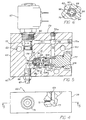
- FIGURES 4 and 5 to consider the composite integrated structure of the control 37 as embodied in a block 60.
- the block 60 is affixed in the hydraulic system 16 by screws (not shown) extending through boxes 63 (FIGURE 5).
- the block 60 accommodates fluid flow in multiple paths as described above to enable the lift to move at select speeds.
- a staged bore 74 (left) extends through the block 39 from top to bottom.
- the top portion of the staged bore 74 forms a cavity 78 configured to receive a normally closed spool valve 80 actuated by a solenoid 82.
- an upper bore 72 extends from the cavity 78 to the right-hand side of the block 39 as shown, passing through a bore 69 at a right angle.
- a plug 72a seals the end of the bore 72 opposite the cavity 78.
- the movable orifice 88 defines a substantially square outside body section 92 (FIGURE 6).
- the diagonal of the body section 92 is smaller than the diameter of the bore 76, permitting the movable orifice 88 to shift freely within the bore.
- the tapered section 90 defines a relatively small orifice 94 while the body section 92 has a flow passage 96 therethrough and lateral perforations 98 through each of its four sides. Accordingly, the flow passage 96 is in fluid communication with the gaps formed between the sides of the body section 92 and the adjacent surface of the bore 76.
- the movable orifice 88 (FIGURE 5) is biased against the seat 86 by a coil spring 100.
- One end of the spring 100 is recessed in the flow passage 96.
- the other end of the spring 100 abuts a contact surface 102 of a cartridge 104 set in the bore 76.
- An O-ring 104a seals the cartridge 104 in the bore 76.
- a relatively large orifice 105 through the portion of the cartridge proximate the contact surface, intersects with a transverse bore 68 and together they connect the bore 76 to bore 70.
- the relatively small orifice 94 in movable orifice 88 has a diameter that is smaller than the relatively large orifice 105 in the cartridge 104.
- the bore 70 disposed parallel to the bore 74, extends from the top of block 39, intersects the bore 72 and terminates in the mid-portion of a bore 76, connecting the bores 72 and 76.
- a plug 70a seals the entry of the bore 70 opposite the bore 76.
- a bore 69 (coupled to the pump 40) lies orthogonal to the plane formed by the bores 70 and 72. The bore 69 extends from the intersection of bores 70 and 72 to the surface of the block 39.
- Threads on the surface of the lower end of bore 74 form a cylinder port 66 that threadably couples with a cylinder line 67 to connect the block 39 with the cylinders 38.
- the surface of the end of the bore 69 (opposite the intersection with the bores 70 and 72) connects the block 39 to the pump assembly 36.
- one fluid path is from the pump port 69 through the bores 72 and 74, then to the cylinder port 66.
- the path accommodates flow to raise and lower the platform 12 between positions G and E. It is represented by the passage 57 in FIGURE 3.
- a second fluid path is from the pump port 69 through bores 70, 76, and a portion of the bore 74 to the cylinder port 66.
- the path accommodates flow attendant movement between the positions E and S.
- the path is represented in FIGURE 3 by the two paths 55 and 56 passing fluid in two directions, one more restricted than the other. As indicated above, the stowing pattern is powered and, consequently, flow is more restricted to accomplish the desired speed of motion.
- the spool valve 80 is closed.
- the fluid is subjected to relatively smaller pressure as it travels (left to right) from the cylinder port 66 to the pump port 69 forced by the weight of the lift L.
- the movable orifice 88 is unseated, permitting the fluid to pass around and through the movable orifice without substantial obstruction.
- the fluid does encounter the relatively large control orifice 105 for some reduced flow.
- the spool valve 80 When the platform 12 is to be stored or stowed, the spool valve 80 is closed. However, by action of the pump 40, the fluid is subjected to relatively greater pressure as it travels in the direction from the pump port 69 to cylinder port 66. The fluid flows through the bore 70 into the transverse bore 68 and then through the relatively large orifice 105, causing some reduction in the flow rate. Then, the fluid encounters the movable orifice 86 in its seated position so that flow is substantially obstructed to accomplish the desired rate and motion speed as fluid emerges into the bore 74 and passes to the cylinders.
- the orifice sizes are selected so that final flow rates, and consequently the rates of platform movement during both deployment and storage, are substantially equal.
- the operation requires that the effective orifice encountered by the fluid subjected to the higher pressure difference (during storage) be smaller than the effective orifice encountered by the fluid subjected to the lower pressure difference (during deployment).
- the lock-block 109 is affixed to the underside of the bridge plate 34 by a set of fasteners 111.
- the lock-block 109 may be made of a low friction, rigid, plastic material and is of generally parallelepiped configuration, however, defining a horizontal detent 115 at the surface outboard of the vehicle V.
- FIGURE 7 illustrates the mechanism with the lift L in the stowed position S. Accordingly, as the lift L tends to drift, the motion would be as indicated by an arrow 117 to the left as depicted. However, such movement is checked by a latch bar 119 received in the detent 115.
- the latch bar 119 is carried on an elongate rotary shaft or rod 121 that is actuated as disclosed below to pivot the latch bar 119 to a disengaged ramp position as illustrated in phantom by the latch bar 119a. Accordingly, when released, the rod 121 is revolved in a counter clockwise direction and the bridge plate 34 is free to move to the left, as indicated by the arrow 117, the motion being accommodated by the lock-block 109 simply riding over the latch bar 119. Thus, acting through the bridge plate 34, the platform 12, and indeed the entire lift L is locked in the stowed position S (FIGURE 2) until the latch bar 119 is released.
- the mechanism for controlling the latch bar 119 is disclosed in greater detail below along with the somewhat related mechanism for lifting and lowering the bridge plate 34 as it is carried through the different positions by the platform 12.
- the shaft or rod 121 extends laterally through the bridge plate 34 (FIGURE 9) to be mounted external of the bracket 28 (FIGURE 1).
- the exterior of the bracket 28 is shown in FIGURE 8 along with the mechanism 125 for controlling the rod 121.
- the rod 121 carries a crank arm 127, the upper end of which is coupled by a coil spring 129 to holding post 131.
- the coil spring 129 acts as a rigid column holding the crank arm 127 positioned to the right as illustrated in FIGURE 8. Accordingly, the latch bar 119 (FIGURE 7) is held in locking engagement with the lock-block 109.
- the coil spring 129 is "broken", simply bent to accommodate a leftward pivotal motion by the crank arm 127. The bending or “breaking" of the spring 129 allows it to be driven to a loop, as shown in phantom, and is accomplished by a wire loop 132 affixed to the armature of a solenoid 133.
- the solenoid 133 is pulsed when the control unit 16 is actuated to initiate lowering the lift from the stowed position S. Accordingly, when the solenoid 133 is energized, its armature raises the wire loop 132 "breaking" the spring 129 into an inverted “U”-shaped configuration. Consequently, the crank arm 127 swings to the left (as illustrated) revolving the shaft 121 to disengage the latch bar 119, moving it into a ramp position as indicated by the phantom bar 119a (FIGURE 7).
- the bridge plate 34 not only serves as a locking element and a bridge ramp, but additionally functions as an inward roll stop. Consequently, the bridge plate 34 (FIGURE 1) is variously positioned between substantially vertical and substantially horizontal positions as the lift is raised and lowered. Generally, as indicated above, the operation is accomplished by a pair of similar cams 35 (FIGURE 1) driven by the upper parallelograms 17 to actuate cables coupled to the bridge plate 34.
- the motion of the bridge plate 34 is meaningful in relation to the platform surface 15.
- the bridge plate 34 is somewhat vertical functioning as a roll stop.
- the bridge plate 34 remains in the somewhat vertical position during the raise-lower motion pattern between the positions G and E.
- the bridge plate 34 swings down to a parallel position substantially flush with the platform surface 15, bridging the space to the base 33.
- the wheelchair is afforded a smooth surface into the vehicle V.
- the bridge plate 34 when the platform 12 moves from a substantially horizontal position to a substantially vertical position, the bridge plate 34 again becomes substantially perpendicular to the surface 15. That is, when the platform 12 is vertical in the stowed position S, the bridge plate 34 is substantially horizontal functioning as a latch member, as described above, to accomplish the positions of the bridge plate 34, the cam 35, actuated by the upper parallelogram 17, in turn, actuates a cable connected to the bridge plate 34. Again, similar cams 35 with cables are provided on each side of the lift mounted on the channel arms 27.
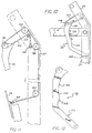
- the cam 35 is pivotally mounted on a bearing pin 140 at an upward location in the channel arm 27.
- a cam follower 142 rides over the compound cam edge 144 to variously position its top end 146 which carries a pulley 148.
- a cable 150 rides on the pulley 148 with an upper end anchored in the end 25 of the channel arm 27. The opposed end of the cable 150 threads through a series of pulleys, as illustrated in FIGURE 11, and is connected to the bridge plate 34.
- the cable 150 is anchored to the channel arm 27 by a stud 152.
- the cable then extends from the stud 152 over an idler 154, the pulley 148 and a pair of pulleys 156 and 158 to extend downwardly within the channel arm 27.
- the cable 150 is received over another pulley 160 before passing to an attachment 162 on the bridge plate 34.
- the cam edge 144 (FIGURE 12) defines three distinct cam drives.
- the uppermost arcuate section 166 engages the cam follower 142 to be swung out from the channel arm 27, raising the bridge plate 34 to the position illustrated in FIGURE 1.
- the collapsing upper parallelogram 17 is accommodated by the arcuate section 166 of the cam holding the bridge plate 34 somewhat vertical until the section 168 engages the cam follower 142 to lower the bridge plate 34.
- the last section 170 of the cam becomes active to set the bridge plate 34 somewhat perpendicular to the surface 15. Accordingly, the bridge plate 34 is horizontal for the locking engagement as described above.
- a need is recognized to interlock the upper and lower parallelograms 17 and 19 so as to force cooperative motions as the lift L moves between the positions S and E.
- the locking engagement is accomplished by the saddle block 58 (FIGURE 2) being engaged to the parallel link 24 during the cooperative pivotal motion pattern.
- FIGURE 13 shows the saddle block assembly 58 somewhat enlarged form along with the supporting pivot bars 52 and 54 and the parallel link 24.
- the sectional view of FIGURE 14 illustrates the selective locked engagement between the saddle lock assembly 58 and the parallel link 24 as now will be considered in greater detail.
- the saddle block assembly 58 includes a yoke section 182 of channel configuration with a sliding shoe 184 of frictionless plastic set to engage the parallel link 24 (FIGURE 13).
- a capped stud 186 Extending from the yoke section 182 through the shoe 84 is a capped stud 186 of a somewhat "mushroom" configuration.
- a circular opening 188 is provided in the parallel link 24 aligned with the stud 186 when the lift is in the entry position E as illustrated in FIGURE 2.
- Extending from the opening 188, parallel with the link 24, is a slot 190 to accommodate the short shaft 192 of the stud 186 with the head 194 inside the slot 190.
- the head 194 of the stud 186 enters the opening 188 as the lift is raised into the entry position E.
- the lower parallelogram 19 is locked to the upper parallelogram 17.
- the stud 186 is slidingly engaged with the link 24, locking the saddle block assembly in sliding engagement.
- the two parallelogram structures 17 and 19 move in a cooperative action as the lift L moves between the entry position E and the stowed position S.
- the lower parallelogram structure 19 is forced to open, allowing the platform 12 to swing down.
- the stud 86 allows withdrawal of the saddle block assembly 58, permitting the two parallelogram structures 17 and 19 to separate and accommodate the independent transporting platform motion patterns.
Landscapes
- Health & Medical Sciences (AREA)
- Engineering & Computer Science (AREA)
- Public Health (AREA)
- Animal Behavior & Ethology (AREA)
- Mechanical Engineering (AREA)
- Life Sciences & Earth Sciences (AREA)
- Transportation (AREA)
- General Health & Medical Sciences (AREA)
- Veterinary Medicine (AREA)
- Vehicle Step Arrangements And Article Storage (AREA)
- Handcart (AREA)
- Regulating Braking Force (AREA)
- Supporting Of Heads In Record-Carrier Devices (AREA)
Claims (12)
- Système de levage de fauteuil roulant (L) pour un véhicule (V), dans lequel une structure à plate-forme (12), servant à porter le fauteuil roulant, est montée sur un mécanisme pivotant (13) qui est destiné à être fixé au véhicule (V) et qu'il est possible d'actionner de façon sélective pour déplacer la structure à plate-forme (12) entre au moins une position d'entrée et une position de rangement, et une plaque de pont (34) est fixée de manière pivotante à la structure à plate-forme (12) pour enjamber un espace entre la structure à plate-forme (12) et le véhicule (V) dans la position d'entrée, caractérisé en ce que la plaque de pont (34) est agencée pour que, lorsque la structure à plate-forme (12) est dans la position de rangement, elle soit effectivement verrouillée dans cette position par l'intermédiaire de la plaque de pont (34).
- Système de levage de fauteuil roulant (L) selon la revendication 1, dans lequel la structure à plate-forme (12) peut être actionnée de façon sélective pour se déplacer entre une position de chargement et les positions d'entrée et de rangement.
- Système de levage de fauteuil roulant (L) selon la revendication 2, dans lequel la plaque de pont (34) est inclinée pour agir comme butée de roulement tandis que la structure à plate-forme (12) est dans la position de chargement.
- Système de levage de fauteuil roulant (L) selon l'une des revendications 1 à 3, dans lequel un mécanisme de verrouillage (119, 121, 127) libérable de façon sélective et destiné à être fixé au véhicule (V), est opératoire pour bloquer le mouvement de la plaque de pont (34), et donc de la structure à plate-forme (12), lorsque la structure à plate-forme (12) est dans la position de rangement.
- Système de levage de fauteuil roulant (L) selon la revendication 4, dans lequel le mécanisme de verrouillage (119, 121, 127) est maintenu dans sa condition d'actionnement par une retenue élastique (129), et des moyens (133) sont actionnables de façon sélective pour dévier la retenue élastique (129) de manière à libérer le mécanisme de verrouillage (119, 121, 127) de sa condition d'actionnement et de permettre ainsi à la structure à plate-forme (12) de se déplacer à partir de la position de rangement.
- Système de levage de fauteuil roulant (L) selon l'une des revendications 1 à 5, dans lequel la plaque de pont (34) comporte un bloc de verrouillage (109) apte à pénétrer dans un puits (41) défini dans une base (37) fixée au véhicule (V), lorsque la structure à plate-forme (12) se déplace vers la position de rangement.
- Système de levage de fauteuil roulant (L) selon la revendication 6, dans lequel le bloc de verrouillage (109) est porté sur la face inférieure de la plaque de pont (34).
- Système de levage de fauteuil roulant (L) selon la revendication 6 ou la revendication 7, dans lequel un mécanisme à manivelle (121, 127) comporte une partie (119) pour empêcher le mouvement du bloc de verrouillage (109) dans le puits (41) de manière à bloquer efficacement la structure à plate-forme (12) dans la position de rangement comme mentionné ci-dessus.
- Système de levage de fauteuil roulant (L) selon la revendication 8, dans lequel un ressort (129) agit sur le mécanisme à manivelle (121, 127) pour le solliciter élastiquement dans une position dans laquelle ladite partie empêche le mouvement du bloc de verrouillage (109) dans le puits (41), et un solénoïde (133) peut être actionné pour dévier sélectivement le ressort (129) et ainsi re-dirigé la sollicitation élastique de sorte que ladite partie (119) se déplace dans une position dans laquelle un mouvement du bloc de verrouillage (109) dans le puits (41) est pratiquement non-empêché.
- Système de levage de fauteuil roulant (L) selon l'une des revendications 1 à 9, dans lequel le mécanisme pivotant (13) comprend au moins une paire de barres inférieures de pivot et de support (19) et au moins une structure supérieure à parallélogramme (17) qui sont mutuellement verrouillées de manière libérable pendant une partie pré-déterminée du mouvement de la structure à plate-forme (12).
- Système de levage de fauteuil roulant (L) selon la revendication 10, dans lequel le mécanisme pivotant (13) comprend des moyens d'entraínement (38) qui sont actionnables pour ouvrir et fermer la structure à parallélogramme (17) pour déplacer la structure à plate-forme (12) entre ses positions définies.
- Système de levage de fauteuil roulant (L) selon l'une des revendications 1 à 11, comprenant un mécanisme à came (142, 144) pour élever et abaisser la plaque de pont (34) en fonction du mouvement de la structure à plate-forme (12) entre ses positions définies.
Applications Claiming Priority (3)
| Application Number | Priority Date | Filing Date | Title |
|---|---|---|---|
| US114774 | 1993-08-31 | ||
| US08/114,774 US5445488A (en) | 1992-07-28 | 1993-08-31 | Locking wheelchair lift |
| EP94917257A EP0716588B1 (fr) | 1993-08-31 | 1994-03-29 | Blocage d'une plate-forme elevatrice pour fauteuil roulant |
Related Parent Applications (1)
| Application Number | Title | Priority Date | Filing Date |
|---|---|---|---|
| EP94917257A Division EP0716588B1 (fr) | 1993-08-31 | 1994-03-29 | Blocage d'une plate-forme elevatrice pour fauteuil roulant |
Publications (2)
| Publication Number | Publication Date |
|---|---|
| EP0911007A1 EP0911007A1 (fr) | 1999-04-28 |
| EP0911007B1 true EP0911007B1 (fr) | 2003-05-21 |
Family
ID=22357348
Family Applications (2)
| Application Number | Title | Priority Date | Filing Date |
|---|---|---|---|
| EP94917257A Expired - Lifetime EP0716588B1 (fr) | 1993-08-31 | 1994-03-29 | Blocage d'une plate-forme elevatrice pour fauteuil roulant |
| EP98120804A Expired - Lifetime EP0911007B1 (fr) | 1993-08-31 | 1994-03-29 | Elévateur pour fauteuil roulant |
Family Applications Before (1)
| Application Number | Title | Priority Date | Filing Date |
|---|---|---|---|
| EP94917257A Expired - Lifetime EP0716588B1 (fr) | 1993-08-31 | 1994-03-29 | Blocage d'une plate-forme elevatrice pour fauteuil roulant |
Country Status (5)
| Country | Link |
|---|---|
| US (2) | US5445488A (fr) |
| EP (2) | EP0716588B1 (fr) |
| AU (1) | AU705929B2 (fr) |
| CA (1) | CA2168761C (fr) |
| WO (1) | WO1995006452A1 (fr) |
Families Citing this family (32)
| Publication number | Priority date | Publication date | Assignee | Title |
|---|---|---|---|---|
| US5865593A (en) * | 1996-12-31 | 1999-02-02 | Lift-U, Division Of Hogan Mfg., Inc. | Wheelchair lift with wheelchair barrier platform interlock mechanism |
| US6039528A (en) * | 1996-12-31 | 2000-03-21 | Lift-U, Division Of Hogan Manufacturing, Inc. | Wheelchair lift with improved outer, inner, and side barriers |
| US6065924A (en) * | 1998-05-01 | 2000-05-23 | The Braun Corporation | Wheelchair lift platform having internal gas spring deployment from stowage position |
| US6238169B1 (en) * | 1998-05-01 | 2001-05-29 | The Braun Corporation | Dual function inboard barrier/bridgeplate assembly for wheelchair lifts |
| USD440728S1 (en) | 1999-01-25 | 2001-04-17 | Phillip E. Schlangen | Wheelchair lift |
| US6435804B1 (en) | 1999-05-19 | 2002-08-20 | Mark Hutchins | Lifting apparatus |
| US6386817B1 (en) * | 1999-09-10 | 2002-05-14 | Wanda M. Cash | Apparatus and method for mounting and transporting a wheelchair upon a towing frame of a vehicle |
| US6599079B1 (en) | 2000-01-12 | 2003-07-29 | The Braun Corporation | Apparatus for locking a wheelchair lift in the stowed position |
| US6461097B1 (en) | 2000-09-29 | 2002-10-08 | Maxon Lift Corporation | Wheelchair lift device |
| US6948903B2 (en) | 2001-03-15 | 2005-09-27 | Maxon Lift Corporation | Unitary liftgate |
| US20040156705A1 (en) * | 2001-03-15 | 2004-08-12 | Karapet Ablabutyan | Unitary lift gate |
| US7290975B2 (en) | 2001-03-17 | 2007-11-06 | Mechanical Tech & Engineering Co. | Two-speed passenger lift and pump assembly therefor |
| US6802095B1 (en) * | 2002-01-25 | 2004-10-12 | Ricon Corporation | Ramp assembly having a lift and lock mechanism |
| US7004454B2 (en) * | 2002-07-01 | 2006-02-28 | Ultimate Lift, Inc | Motorcycle and small vehicle lift |
| US6726435B1 (en) | 2002-10-08 | 2004-04-27 | Chadco Enterprises, Inc. | Lift for a personal mobility vehicle or wheelchair |
| US6837670B2 (en) * | 2003-01-29 | 2005-01-04 | The Braun Corporation | Wheelchair access system with stacking platform |
| DE20309868U1 (de) * | 2003-06-25 | 2004-11-04 | Apener Maschinenbau und Förderanlagen Gustav Bruns GmbH & Co KG | Fahrzeuglift für Lasten, insbesondere für Rollstühle |
| US20050077111A1 (en) * | 2003-10-14 | 2005-04-14 | The Braun Corporation | Threshold switch apparatus for a mobility access device |
| US7261229B1 (en) * | 2004-04-28 | 2007-08-28 | R.A. Allen Company, Inc. | Swing-away hitch mounted equipment carrier |
| US7556467B2 (en) * | 2005-04-06 | 2009-07-07 | Maxon Lift Corporation | Apparatus for level lift ride |
| US7467917B2 (en) * | 2006-02-03 | 2008-12-23 | Ricon Corporation | Slidably collapsible two arm wheelchair lift |
| US7445416B2 (en) * | 2006-02-03 | 2008-11-04 | Ricon Corp. | Wheelchair lift with slidable support arm |
| DE102007059943B4 (de) * | 2007-12-12 | 2010-02-04 | Hübner Transportation GmbH | Rollstuhlhubvorrichtung |
| WO2009134837A1 (fr) * | 2008-05-01 | 2009-11-05 | Ricon Corp. | Logique anti-pliage à pression statique pour élévateurs de fauteuils roulants dotés d’une plateforme |
| US8113760B1 (en) | 2008-05-12 | 2012-02-14 | Sean Schroll | Secure loading system |
| GB2470746B (en) * | 2009-06-03 | 2013-03-06 | Richard Fletcher | Compact wheelchair platform |
| US8998558B2 (en) * | 2009-09-24 | 2015-04-07 | Mobility Svm, Llc | Vehicle wheelchair lift |
| IT1399641B1 (it) * | 2010-04-22 | 2013-04-26 | Car Oil System S R L | Sollevatore interno a doppio braccio. |
| DE202012002832U1 (de) * | 2012-03-21 | 2013-06-25 | Gustav Bruns Maschinenbau und Förderanlagen GmbH & Co. KG | Fahrzeuglift mit Vorspanneinrichtung |
| US9101519B2 (en) | 2013-02-07 | 2015-08-11 | Dallas Smith Corporation | Leveling ramp for a wheelchair |
| US10500110B2 (en) | 2017-06-20 | 2019-12-10 | Tyler Taschner | Wheelchair loading system |
| CA3079328A1 (fr) | 2019-04-25 | 2020-10-25 | Mpower Mobility, Inc | Levage de plateforme avec capteur de passager, eclairage et verrouillage de la plateforme ameliores |
Family Cites Families (25)
| Publication number | Priority date | Publication date | Assignee | Title |
|---|---|---|---|---|
| US2470778A (en) * | 1946-06-25 | 1949-05-24 | Matthew B Butler | Hydraulic system for selfloading trucks |
| US2500815A (en) * | 1947-03-10 | 1950-03-14 | Gerli | Flying stage |
| US3415161A (en) * | 1966-12-12 | 1968-12-10 | Clark Equipment Co | Piston stroke limit means |
| US3764030A (en) * | 1971-12-29 | 1973-10-09 | Harsco Corp | Side mount loading platform for van type truck |
| US4124100A (en) * | 1978-02-13 | 1978-11-07 | General Motors Corporation | Locking arrangement for wheelchair lift device |
| JPS56124560A (en) * | 1980-03-03 | 1981-09-30 | Jidosha Kiki Co Ltd | Pressurized fluid supply device for power steering arrangment |
| US4474527A (en) * | 1982-06-25 | 1984-10-02 | Reb Manufacturing, Inc. | Optional manual gravity wheelchair lift |
| GB8311632D0 (en) * | 1983-04-28 | 1983-06-02 | Fretwell Ltd P & J | Vehicle lift devices |
| US4534450A (en) * | 1984-04-30 | 1985-08-13 | Pierre Savaria | Invalid lift |
| US4583907A (en) * | 1984-05-18 | 1986-04-22 | Wimberley Ronald J | Extensible apparatus |
| DE3506180A1 (de) * | 1985-02-22 | 1986-08-28 | Festo KG, 7300 Esslingen | Kolben-zylinder-anordnung |
| US4664584A (en) * | 1985-03-21 | 1987-05-12 | The Braun Corporation | Rotary wheelchair lift |
| US4821622A (en) * | 1986-12-22 | 1989-04-18 | Deere & Company | Extension and retraction sequencing circuit |
| US4783043A (en) * | 1987-05-04 | 1988-11-08 | Sundstrand Corporation | Hydraulic snub valve |
| JP2725006B2 (ja) * | 1987-08-18 | 1998-03-09 | 和光工業株式会社 | 車輛用昇降装置 |
| JPH01105001A (ja) * | 1987-10-16 | 1989-04-21 | Smc Corp | 等速度駆動弁 |
| DE68925368T2 (de) * | 1988-11-05 | 1996-08-14 | Ricon Uk Ltd | Fahrzeuge und ladebordwände |
| US4984955A (en) * | 1989-02-23 | 1991-01-15 | Mccullough Robert C | Lift apparatus |
| US5110252A (en) * | 1990-05-24 | 1992-05-05 | Hogan Mfg., Inc. | Wheelchair lift for transit vehicles having elevated passenger compartment floor |
| US5158419A (en) * | 1990-05-24 | 1992-10-27 | Hogan Mfg., Inc. | Wheelchair lift for transit vehicles having elevated passenger compartment floor |
| US5180275A (en) * | 1991-05-28 | 1993-01-19 | The Braun Corporation | Rotary bus lift with power stowable platform |
| US5142963A (en) * | 1991-10-25 | 1992-09-01 | Spectra-Physics Laserplane, Inc. | Load referenced pressure reducing valve |
| US5261779A (en) * | 1992-01-24 | 1993-11-16 | The Braun Corporation | Dual hydraulic, parallelogram arm wheelchair lift |
| US5228538A (en) * | 1992-02-12 | 1993-07-20 | Ricon Corporation | Passenger lift with an electric safety interlock |
| US5308215A (en) * | 1992-07-28 | 1994-05-03 | Ricon Corporation | Passenger lift movable at variable speeds |
-
1993
- 1993-08-31 US US08/114,774 patent/US5445488A/en not_active Expired - Lifetime
-
1994
- 1994-03-29 WO PCT/US1994/003417 patent/WO1995006452A1/fr not_active Ceased
- 1994-03-29 EP EP94917257A patent/EP0716588B1/fr not_active Expired - Lifetime
- 1994-03-29 CA CA002168761A patent/CA2168761C/fr not_active Expired - Lifetime
- 1994-03-29 EP EP98120804A patent/EP0911007B1/fr not_active Expired - Lifetime
-
1996
- 1996-12-31 US US08/774,411 patent/US5944473A/en not_active Expired - Lifetime
-
1997
- 1997-10-03 AU AU39900/97A patent/AU705929B2/en not_active Ceased
Also Published As
| Publication number | Publication date |
|---|---|
| WO1995006452A1 (fr) | 1995-03-09 |
| US5445488A (en) | 1995-08-29 |
| AU6903094A (en) | 1995-03-22 |
| US5944473A (en) | 1999-08-31 |
| AU705929B2 (en) | 1999-06-03 |
| EP0911007A1 (fr) | 1999-04-28 |
| CA2168761A1 (fr) | 1995-03-09 |
| EP0716588A1 (fr) | 1996-06-19 |
| AU3990097A (en) | 1997-12-18 |
| AU687066B2 (en) | 1998-02-19 |
| EP0716588B1 (fr) | 2000-05-31 |
| CA2168761C (fr) | 1999-08-24 |
Similar Documents
| Publication | Publication Date | Title |
|---|---|---|
| EP0911007B1 (fr) | Elévateur pour fauteuil roulant | |
| US5605431A (en) | Locking wheelchair lift | |
| US7264433B2 (en) | Drive mechanism for a vehicle access system | |
| US5439342A (en) | Safety barrier/ramp actuating mechanism for wheelchair lifts | |
| US6461097B1 (en) | Wheelchair lift device | |
| US5556250A (en) | Vehicle lifts | |
| DE69309042T2 (de) | Passagierlift mit einem elektrischen sicherheitsverschluss | |
| US6802095B1 (en) | Ramp assembly having a lift and lock mechanism | |
| US5391041A (en) | Hydraulically operated bus ramp mechanism | |
| US5832555A (en) | Compact moveable ramp assembly | |
| US6860701B2 (en) | Wheelchair ramp with side barriers | |
| EP0703766B1 (fr) | Dispositif de levage utilise avec un vehicule | |
| US5110252A (en) | Wheelchair lift for transit vehicles having elevated passenger compartment floor | |
| WO1999008641A9 (fr) | Elevateur a plate-forme pliable pour fauteuil roulant | |
| MXPA04007619A (es) | Sistema de cinturon de seguridad para elevadores de sillas de ruedas. | |
| US5308215A (en) | Passenger lift movable at variable speeds | |
| AU687066C (en) | Locking wheelchair lift | |
| US5456504A (en) | Locking and unlocking apparatus for access door on a passenger railway vehicle | |
| WO2003064208A1 (fr) | Ensemble rampe possedant un mecanisme de levage et de verrouillage | |
| JP2005083033A (ja) | 建設機械の昇降装置 | |
| US20020136624A1 (en) | Lift device with variable speed actuation | |
| JP2009090960A (ja) | 昇降装置 | |
| JPH11147436A (ja) | デッキ昇降装置 | |
| US20260091964A1 (en) | Stowable deck for aerial work platform | |
| JP2005016138A (ja) | 可動体の駆動装置 |
Legal Events
| Date | Code | Title | Description |
|---|---|---|---|
| PUAI | Public reference made under article 153(3) epc to a published international application that has entered the european phase |
Free format text: ORIGINAL CODE: 0009012 |
|
| AC | Divisional application: reference to earlier application |
Ref document number: 716588 Country of ref document: EP |
|
| AK | Designated contracting states |
Kind code of ref document: A1 Designated state(s): GB |
|
| RIN1 | Information on inventor provided before grant (corrected) |
Inventor name: TREMBLAY, NELSON Inventor name: TREMBLAY, JULES Inventor name: SAVARIA, PIERRE Inventor name: SAUCIER, STANTON DAVID |
|
| 17P | Request for examination filed |
Effective date: 19991019 |
|
| GRAH | Despatch of communication of intention to grant a patent |
Free format text: ORIGINAL CODE: EPIDOS IGRA |
|
| RTI1 | Title (correction) |
Free format text: WHEELCHAIR LIFT |
|
| GRAH | Despatch of communication of intention to grant a patent |
Free format text: ORIGINAL CODE: EPIDOS IGRA |
|
| GRAA | (expected) grant |
Free format text: ORIGINAL CODE: 0009210 |
|
| AC | Divisional application: reference to earlier application |
Ref document number: 0716588 Country of ref document: EP Kind code of ref document: P |
|
| AK | Designated contracting states |
Designated state(s): GB |
|
| REG | Reference to a national code |
Ref country code: GB Ref legal event code: FG4D |
|
| PLBE | No opposition filed within time limit |
Free format text: ORIGINAL CODE: 0009261 |
|
| STAA | Information on the status of an ep patent application or granted ep patent |
Free format text: STATUS: NO OPPOSITION FILED WITHIN TIME LIMIT |
|
| 26N | No opposition filed |
Effective date: 20040224 |
|
| PGFP | Annual fee paid to national office [announced via postgrant information from national office to epo] |
Ref country code: GB Payment date: 20130327 Year of fee payment: 20 |
|
| REG | Reference to a national code |
Ref country code: GB Ref legal event code: PE20 Expiry date: 20140328 |
|
| PG25 | Lapsed in a contracting state [announced via postgrant information from national office to epo] |
Ref country code: GB Free format text: LAPSE BECAUSE OF EXPIRATION OF PROTECTION Effective date: 20140328 |