EP0911102A1 - Fraise à queue et plaquette de coupe - Google Patents
Fraise à queue et plaquette de coupe Download PDFInfo
- Publication number
- EP0911102A1 EP0911102A1 EP98110089A EP98110089A EP0911102A1 EP 0911102 A1 EP0911102 A1 EP 0911102A1 EP 98110089 A EP98110089 A EP 98110089A EP 98110089 A EP98110089 A EP 98110089A EP 0911102 A1 EP0911102 A1 EP 0911102A1
- Authority
- EP
- European Patent Office
- Prior art keywords
- end mill
- indexable
- mill body
- indexable insert
- face
- Prior art date
- Legal status (The legal status is an assumption and is not a legal conclusion. Google has not performed a legal analysis and makes no representation as to the accuracy of the status listed.)
- Withdrawn
Links
- 230000000630 rising effect Effects 0.000 description 6
- 238000010586 diagram Methods 0.000 description 2
- 230000004048 modification Effects 0.000 description 2
- 238000012986 modification Methods 0.000 description 2
- 230000002452 interceptive effect Effects 0.000 description 1
Images

Classifications
-
- B—PERFORMING OPERATIONS; TRANSPORTING
- B23—MACHINE TOOLS; METAL-WORKING NOT OTHERWISE PROVIDED FOR
- B23C—MILLING
- B23C5/00—Milling-cutters
- B23C5/02—Milling-cutters characterised by the shape of the cutter
- B23C5/10—Shank-type cutters, i.e. with an integral shaft
- B23C5/1009—Ball nose end mills
- B23C5/1027—Ball nose end mills with one or more removable cutting inserts
- B23C5/1045—Ball nose end mills with one or more removable cutting inserts having a cutting insert, the cutting edge of which subtends substantially 90 degrees
-
- Y—GENERAL TAGGING OF NEW TECHNOLOGICAL DEVELOPMENTS; GENERAL TAGGING OF CROSS-SECTIONAL TECHNOLOGIES SPANNING OVER SEVERAL SECTIONS OF THE IPC; TECHNICAL SUBJECTS COVERED BY FORMER USPC CROSS-REFERENCE ART COLLECTIONS [XRACs] AND DIGESTS
- Y10—TECHNICAL SUBJECTS COVERED BY FORMER USPC
- Y10T—TECHNICAL SUBJECTS COVERED BY FORMER US CLASSIFICATION
- Y10T407/00—Cutters, for shaping
- Y10T407/19—Rotary cutting tool
- Y10T407/1906—Rotary cutting tool including holder [i.e., head] having seat for inserted tool
- Y10T407/1908—Face or end mill
- Y10T407/1924—Specified tool shape
-
- Y—GENERAL TAGGING OF NEW TECHNOLOGICAL DEVELOPMENTS; GENERAL TAGGING OF CROSS-SECTIONAL TECHNOLOGIES SPANNING OVER SEVERAL SECTIONS OF THE IPC; TECHNICAL SUBJECTS COVERED BY FORMER USPC CROSS-REFERENCE ART COLLECTIONS [XRACs] AND DIGESTS
- Y10—TECHNICAL SUBJECTS COVERED BY FORMER USPC
- Y10T—TECHNICAL SUBJECTS COVERED BY FORMER US CLASSIFICATION
- Y10T407/00—Cutters, for shaping
- Y10T407/19—Rotary cutting tool
- Y10T407/1946—Face or end mill
- Y10T407/1948—Face or end mill with cutting edge entirely across end of tool [e.g., router bit, end mill, etc.]
-
- Y—GENERAL TAGGING OF NEW TECHNOLOGICAL DEVELOPMENTS; GENERAL TAGGING OF CROSS-SECTIONAL TECHNOLOGIES SPANNING OVER SEVERAL SECTIONS OF THE IPC; TECHNICAL SUBJECTS COVERED BY FORMER USPC CROSS-REFERENCE ART COLLECTIONS [XRACs] AND DIGESTS
- Y10—TECHNICAL SUBJECTS COVERED BY FORMER USPC
- Y10T—TECHNICAL SUBJECTS COVERED BY FORMER US CLASSIFICATION
- Y10T407/00—Cutters, for shaping
- Y10T407/21—Arc segment tool
-
- Y—GENERAL TAGGING OF NEW TECHNOLOGICAL DEVELOPMENTS; GENERAL TAGGING OF CROSS-SECTIONAL TECHNOLOGIES SPANNING OVER SEVERAL SECTIONS OF THE IPC; TECHNICAL SUBJECTS COVERED BY FORMER USPC CROSS-REFERENCE ART COLLECTIONS [XRACs] AND DIGESTS
- Y10—TECHNICAL SUBJECTS COVERED BY FORMER USPC
- Y10T—TECHNICAL SUBJECTS COVERED BY FORMER US CLASSIFICATION
- Y10T407/00—Cutters, for shaping
- Y10T407/23—Cutters, for shaping including tool having plural alternatively usable cutting edges
- Y10T407/235—Cutters, for shaping including tool having plural alternatively usable cutting edges with integral chip breaker, guide or deflector
Definitions
- the present invention generally relates to an indexable end mill wherein an indexable insert is mounted to a round distal end portion of an end mill body as protruded from the end mill body and also relates to the indexable insert mounted to the indexable end mill.
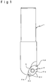
- an indexable end mill arranged such that, as shown in Fig.1, an indexable insert 2 is mounted to a round distal end portion of an end mill body 1 as protruded from the end mill body 1.
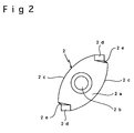
- the prior-art indexable insert mounted to the distal end portion of such an end mill body 1 has a substantially elliptical shape in plan, including a mounting hole 2b defined at a center of its cutting face 2a for mounting the indexable insert 2 to the end mill body 1 by means of a screw 3, and two cutting edges 2c each formed in an arcuate shape.
- the indexable end mill with the indexable insert 2 protruded from the end mill body 1 has been used for cutting a workpiece (not shown) in a manner such that the indexable end mill is rotated with the indexable insert 2 pressed against the workpiece thereby cutting the workpiece from top like a drill.
- each end face 2d is formed by cutting away an end portion of the cutting face 2a corresponding to a rotation center of the indexable end mill rotated for cutting the workpiece, the cut-away portion being in a bent form extended from place corresponding to the rotation center of the end mill body.
- the indexable insert 2 is arranged such that chip removed by the cutting edge 2c at a rotation-center portion of the indexable insert is guided along the end face 2d to the cutting face 2a for discharge.
- the chip removed by the cutting edge 2c at the rotation-center portion of the indexable insert 2 is held by a face 2e rising from the end face 2d to the cutting face 2a so that the rotation-center portion of the indexable insert 2 becomes blocked with the removed chip which, in turn, is fused thereto.
- the indexable insert 2 is subject to an excessive load, resulting in a breakage thereof or a reduced cutting performance thereof which lowers the cutting precision of the end mill. As a result, the end mill cannot ensure stability and high precision of the cutting work.
- the present invention is directed to a solution to the aforementioned problem of the indexable end mill arranged such that the indexable insert is mounted to the round distal end portion of the end mill body as protruded from the end mill body.
- An object of the invention is to provide an indexable end mill adapted to facilitate discharge of chips produced by cutting a workpiece thereby to prevent the resultant chips from being fused to a rotation-center portion of an indexable insert protruded from an end mill body, in cases where the indexable end mill is rotated with the indexable insert pressed against the workpiece for cutting the workpiece from top like a drill.
- Another object of the invention is to provide an indexable end mill adapted to reduce load on the indexable insert during the cutting work thereby to prevent a breakage thereof or reduced cutting performance of the indexable end mill, thus ensuring stability and high precision of the cutting work.
- the indexable end mill comprises an end mill body having a round distal end portion and an indexable insert mounted to the end mill body as protruded from the round distal end portion thereof, the indexable end mill wherein an end face is formed by cutting away an end portion of the indexable insert at a rotation center of a cutting edge thereof, the end face having an edge closer to the end mill body extended outward from the rotation center as inclined rearwardly with respect to a line L orthogonal to an axis of the end mill body.
- the end face of the indexable insert has an edge closer to the end mill body inclined rearwardly with respect to the line L orthogonal to the axis of the end mill body and therefore, unlike the prior-art configuration of the indexable insert, the face rising from the edge of the end face is prevented from holding the chip removed by the cutting edge at the rotation-center portion of the indexable insert. Hence, the removed chip is discharged along the end face so that the rotation-center portion of the indexable insert is prevented from becoming blocked with the removed chip.
- the indexable end mill according to the invention assuredly prevents the removed chip from being fused to the rotation-center portion of the indexable insert. As a result, there occurs no breakage of the indexable insert due to an excessive load thereon during the cutting work nor reduction in the cutting performance of the indexable insert which results in a lowered cutting precision. Thus, the indexable end mill ensures a stable cutting work of high precision even where the workpiece is cut from top as done by the drill.
- the end face of the indexable insert has the edge closer to the end mill body rearwardly inclined with respect to the line L orthogonal to the axis of the end mill body, if the rearward inclination of the edge is at an insufficient angle ⁇ , the face rising from the edge of the end face tends to hold the chip removed by the cutting edge at the rotation-center portion of the indexable insert, interfering with the discharge of the removed chip.
- the edge closer to the end mill body is rearwardly inclined at an angle ⁇ of between 10° and 60° with respect to the line L orthogonal to the axis of the end mill body.
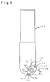
- the indexable end mill includes an insert seat 11 for mounting an indexable insert 20 to a round distal end portion of an end mill body 10, and a pocket 12 continuous to the insert seat 11 for receiving chips.
- the indexable insert 20 mounted to the insert seat 11 at the distal end portion of the end mill body 10 is, as shown in Figs.3 and 4, substantially elliptically shaped in plan and formed with a mounting hole 22 at a central portion of a cutting face 21 thereof for mounting the indexable insert 20 to the insert seat 11 of the end mill body 10 by means of a screw 3.
- the indexable insert 20 is further formed with two cutting edges 23 arcuately extending along an outer circumference of the indexable insert.
- the two cutting edges 23 are arcuately formed along the outer circumference of the indexable insert in order that when one of the cutting edges 23 is worn out due to the cutting work, the indexable insert 20 mounted to the end mill body 10 is rotated 180° so as to allow the use of the other cutting edge 23.
- the indexable insert 20 is formed with end faces 24 at opposite ends thereof where the two cutting edges 23 intersect each other. More specifically, each end face is formed by correspondingly cutting away a portion of the cutting face in a bent form such as projected from a rotation center of the indexable insert 20 to the cutting face 21 thereof, the indexable insert being rotated for the cutting work as mounted to the insert seat 11 of the end mill body 10.
- the end face 24 has an edge 24a closer to the end mill body 10 extended outwardly from the rotation center as inclined rearwardly at an angle ⁇ of 10°-60° with respect to a line L orthogonal to an axis of the end mill body 10.
- the chip removed by the cutting edge 23 at the rotation-center portion of the indexable insert is prevented from being held by and fused to the rotation-center portion of the indexable insert 20.
- This is also effective to avoid an excessive load on the indexable insert 20 during the cutting work, which excessive load results in a breakage or reduced cutting performance of the indexable insert 20, which has been suffered by the prior-art end mill.
- the indexable end mill of the invention ensures stability and high precision of the cutting work even where the workpiece is cut from top as done by the drill.
Landscapes
- Engineering & Computer Science (AREA)
- Mechanical Engineering (AREA)
- Milling Processes (AREA)
Applications Claiming Priority (2)
| Application Number | Priority Date | Filing Date | Title |
|---|---|---|---|
| JP9291074A JPH11123609A (ja) | 1997-10-23 | 1997-10-23 | スローアウェイ式エンドミル及びスローアウェイチップ |
| JP291074/97 | 1997-10-23 |
Publications (1)
| Publication Number | Publication Date |
|---|---|
| EP0911102A1 true EP0911102A1 (fr) | 1999-04-28 |
Family
ID=17764102
Family Applications (1)
| Application Number | Title | Priority Date | Filing Date |
|---|---|---|---|
| EP98110089A Withdrawn EP0911102A1 (fr) | 1997-10-23 | 1998-06-03 | Fraise à queue et plaquette de coupe |
Country Status (4)
| Country | Link |
|---|---|
| US (1) | US6135677A (fr) |
| EP (1) | EP0911102A1 (fr) |
| JP (1) | JPH11123609A (fr) |
| KR (1) | KR19990036524A (fr) |
Cited By (2)
| Publication number | Priority date | Publication date | Assignee | Title |
|---|---|---|---|---|
| CN103418823A (zh) * | 2013-09-03 | 2013-12-04 | 株洲华锐硬质合金工具有限责任公司 | 一种用于铣削加工的刀片及其配套铣刀 |
| CN106624861A (zh) * | 2017-01-24 | 2017-05-10 | 珠海市魅族科技有限公司 | 切削设备及切削加工方法 |
Families Citing this family (5)
| Publication number | Priority date | Publication date | Assignee | Title |
|---|---|---|---|---|
| AT4435U1 (de) * | 2000-09-25 | 2001-07-25 | Plansee Tizit Ag | Wendeschneidplatte zum drehen |
| SE528710C2 (sv) * | 2005-06-01 | 2007-01-30 | Sandvik Intellectual Property | Indexerbart frässkär med kopplingsmedlet anordnat på en släppningsyta |
| USD563440S1 (en) * | 2006-03-17 | 2008-03-04 | Ehwa Diamond Industrial Co., Ltd. | Tip for a grinding wheel |
| JP2009039810A (ja) * | 2007-08-08 | 2009-02-26 | Kumamoto Univ | 繊維強化複合材の穴あけ方法 |
| EP2352610B1 (fr) * | 2008-11-27 | 2017-08-02 | TaeguTec Ltd. | Fraise sphérique à queue et plaquette de coupe double face |
Citations (2)
| Publication number | Priority date | Publication date | Assignee | Title |
|---|---|---|---|---|
| EP0123887A2 (fr) * | 1983-04-29 | 1984-11-07 | NOUVA CA.ME.S. S.p.A. | Dispositif pour fixer une plaquette de coupe au support d'une fraise |
| DE9107615U1 (de) * | 1991-06-20 | 1991-10-24 | Entwicklungszentrum für Zerspanungstechnik GmbH & Co., 7630 Lahr | Zweischneidiges Gesenkwerkzeug zum Fräsen und Bohren |
Family Cites Families (13)
| Publication number | Priority date | Publication date | Assignee | Title |
|---|---|---|---|---|
| JPS5124438A (en) * | 1974-08-09 | 1976-02-27 | Hitachi Ltd | Karyokuburantono kyusokufukaseigensochi |
| JPS5331286A (en) * | 1976-09-02 | 1978-03-24 | Riyousuke Hosoi | Ball end mill |
| JPS5844123U (ja) * | 1981-09-14 | 1983-03-24 | ダイジヱツト工業株式会社 | スロ−アウエイ式ボ−ルエンドミル |
| US4527930A (en) * | 1983-03-23 | 1985-07-09 | Hugh Harroun | Ball nose end cutting tool |
| US4525110A (en) * | 1983-05-18 | 1985-06-25 | Stojan Stojanovski | Indexable ball nose end mill |
| US4679968A (en) * | 1985-06-28 | 1987-07-14 | Mitsubishi Kinzoku Kabushiki Kaisha | Indexable cutter insert |
| DE3807195A1 (de) * | 1987-03-04 | 1988-09-15 | Mitsubishi Metal Corp | Umstellbarer schneideinsatz |
| JPH0621612Y2 (ja) * | 1987-09-28 | 1994-06-08 | 三菱マテリアル株式会社 | スローアウエイチップ |
| US5193943A (en) * | 1992-02-06 | 1993-03-16 | Hyundai Motor Co. | Cutting tool for use in a milling machine |
| US5348426A (en) * | 1993-01-08 | 1994-09-20 | Krupp Ernest E | Ball nose cutter having a single cutter insert |
| US5562370A (en) * | 1995-03-27 | 1996-10-08 | Kennametal Inc. | Insert having sinusoidal undulations for ball nose end mill |
| US5782589A (en) * | 1996-06-17 | 1998-07-21 | Cole; John M. | Milling cutter |
| JPH11138323A (ja) * | 1997-11-11 | 1999-05-25 | Sumitomo Electric Ind Ltd | ボールエンドミル用スローアウェイチップ |
-
1997
- 1997-10-23 JP JP9291074A patent/JPH11123609A/ja active Pending
-
1998
- 1998-06-03 EP EP98110089A patent/EP0911102A1/fr not_active Withdrawn
- 1998-06-10 KR KR1019980021554A patent/KR19990036524A/ko not_active Ceased
- 1998-06-12 US US09/096,495 patent/US6135677A/en not_active Expired - Lifetime
Patent Citations (2)
| Publication number | Priority date | Publication date | Assignee | Title |
|---|---|---|---|---|
| EP0123887A2 (fr) * | 1983-04-29 | 1984-11-07 | NOUVA CA.ME.S. S.p.A. | Dispositif pour fixer une plaquette de coupe au support d'une fraise |
| DE9107615U1 (de) * | 1991-06-20 | 1991-10-24 | Entwicklungszentrum für Zerspanungstechnik GmbH & Co., 7630 Lahr | Zweischneidiges Gesenkwerkzeug zum Fräsen und Bohren |
Cited By (3)
| Publication number | Priority date | Publication date | Assignee | Title |
|---|---|---|---|---|
| CN103418823A (zh) * | 2013-09-03 | 2013-12-04 | 株洲华锐硬质合金工具有限责任公司 | 一种用于铣削加工的刀片及其配套铣刀 |
| CN103418823B (zh) * | 2013-09-03 | 2015-09-02 | 株洲华锐硬质合金工具有限责任公司 | 一种用于铣削加工的刀片及其配套铣刀 |
| CN106624861A (zh) * | 2017-01-24 | 2017-05-10 | 珠海市魅族科技有限公司 | 切削设备及切削加工方法 |
Also Published As
| Publication number | Publication date |
|---|---|
| US6135677A (en) | 2000-10-24 |
| JPH11123609A (ja) | 1999-05-11 |
| KR19990036524A (ko) | 1999-05-25 |
Similar Documents
| Publication | Publication Date | Title |
|---|---|---|
| US8454278B2 (en) | Eight-edged cutting insert, and tool holder for same | |
| US5622460A (en) | Chip cutting tool with acutely angled pocket side walls | |
| US4512689A (en) | Cutting insert and cutting tool therefor | |
| JP3775321B2 (ja) | スローアウェイチップおよびスローアウェイ式切削工具 | |
| JP3503072B2 (ja) | 回転式フライス工具 | |
| JPS61121810A (ja) | ドリル及びその切削植刃 | |
| US4573831A (en) | Cutter blade | |
| US5664914A (en) | Drill | |
| US4679968A (en) | Indexable cutter insert | |
| US8449224B2 (en) | Cutting tool and cutting method | |
| JPH04226827A (ja) | ボールエンドミルとこれに使用するスローアウェイチップ | |
| US6406226B2 (en) | Throwaway tip and drill holder | |
| EP0911102A1 (fr) | Fraise à queue et plaquette de coupe | |
| KR100300007B1 (ko) | 개선된밀링절삭삽입체 | |
| US6851897B2 (en) | Cutting tool insert and cutting tool | |
| US6126365A (en) | Boring tool | |
| JPH04304918A (ja) | エンドミル | |
| JPH11156625A (ja) | スローアウェイチップおよび該スローアウェイチップを装着したスローアウェイ式ボールエンドミル | |
| JP3309664B2 (ja) | スローアウェイ式ボールエンドミル | |
| EP4717383A1 (fr) | Insert de coupe, corps de support et outil de forage rotatif comprenant un tel insert de coupe et corps de support | |
| JPH084963Y2 (ja) | スローアウェイ式ボールエンドミル | |
| JPH11197922A (ja) | スローアウェイチップおよび該スローアウェイチップを装着したスローアウェイ式ドリル | |
| JP4797462B2 (ja) | 回転工具 | |
| JP2001252816A (ja) | スローアウェイ式ボールエンドミル | |
| JPH11300508A (ja) | スローアウェイチップ |
Legal Events
| Date | Code | Title | Description |
|---|---|---|---|
| PUAI | Public reference made under article 153(3) epc to a published international application that has entered the european phase |
Free format text: ORIGINAL CODE: 0009012 |
|
| AK | Designated contracting states |
Kind code of ref document: A1 Designated state(s): DE ES FR GB IT |
|
| AX | Request for extension of the european patent |
Free format text: AL;LT;LV;MK;RO;SI |
|
| 17P | Request for examination filed |
Effective date: 19990622 |
|
| AKX | Designation fees paid |
Free format text: DE ES FR GB IT |
|
| 17Q | First examination report despatched |
Effective date: 20010509 |
|
| STAA | Information on the status of an ep patent application or granted ep patent |
Free format text: STATUS: THE APPLICATION HAS BEEN WITHDRAWN |
|
| 18W | Application withdrawn |
Withdrawal date: 20020305 |