EP0911126A1 - Réglage d'un gabarit a l'aide d'un laser pour la fabrication de fermes et procédé d'utilisation - Google Patents
Réglage d'un gabarit a l'aide d'un laser pour la fabrication de fermes et procédé d'utilisation Download PDFInfo
- Publication number
- EP0911126A1 EP0911126A1 EP98307688A EP98307688A EP0911126A1 EP 0911126 A1 EP0911126 A1 EP 0911126A1 EP 98307688 A EP98307688 A EP 98307688A EP 98307688 A EP98307688 A EP 98307688A EP 0911126 A1 EP0911126 A1 EP 0911126A1
- Authority
- EP
- European Patent Office
- Prior art keywords
- accordance
- work
- truss
- projected
- jig
- Prior art date
- Legal status (The legal status is an assumption and is not a legal conclusion. Google has not performed a legal analysis and makes no representation as to the accuracy of the status listed.)
- Granted
Links
- 238000000034 method Methods 0.000 title claims description 15
- 210000004209 hair Anatomy 0.000 claims description 3
- 238000005096 rolling process Methods 0.000 claims 1
- 238000004519 manufacturing process Methods 0.000 description 8
- 230000000712 assembly Effects 0.000 description 3
- 238000000429 assembly Methods 0.000 description 3
- 238000010276 construction Methods 0.000 description 2
- 230000004048 modification Effects 0.000 description 2
- 238000012986 modification Methods 0.000 description 2
- 229910000831 Steel Inorganic materials 0.000 description 1
- 230000001419 dependent effect Effects 0.000 description 1
- 238000009434 installation Methods 0.000 description 1
- 230000009467 reduction Effects 0.000 description 1
- 239000010959 steel Substances 0.000 description 1
Images


Classifications
-
- B—PERFORMING OPERATIONS; TRANSPORTING
- B27—WORKING OR PRESERVING WOOD OR SIMILAR MATERIAL; NAILING OR STAPLING MACHINES IN GENERAL
- B27F—DOVETAILED WORK; TENONS; SLOTTING MACHINES FOR WOOD OR SIMILAR MATERIAL; NAILING OR STAPLING MACHINES
- B27F7/00—Nailing or stapling; Nailed or stapled work
- B27F7/15—Machines for driving in nail- plates and spiked fittings
- B27F7/155—Machines for driving in nail- plates and spiked fittings for nail plates
-
- B—PERFORMING OPERATIONS; TRANSPORTING
- B23—MACHINE TOOLS; METAL-WORKING NOT OTHERWISE PROVIDED FOR
- B23Q—DETAILS, COMPONENTS, OR ACCESSORIES FOR MACHINE TOOLS, e.g. ARRANGEMENTS FOR COPYING OR CONTROLLING; MACHINE TOOLS IN GENERAL CHARACTERISED BY THE CONSTRUCTION OF PARTICULAR DETAILS OR COMPONENTS; COMBINATIONS OR ASSOCIATIONS OF METAL-WORKING MACHINES, NOT DIRECTED TO A PARTICULAR RESULT
- B23Q16/00—Equipment for precise positioning of tool or work into particular locations not otherwise provided for
- B23Q16/001—Stops, cams, or holders therefor
-
- B—PERFORMING OPERATIONS; TRANSPORTING
- B23—MACHINE TOOLS; METAL-WORKING NOT OTHERWISE PROVIDED FOR
- B23Q—DETAILS, COMPONENTS, OR ACCESSORIES FOR MACHINE TOOLS, e.g. ARRANGEMENTS FOR COPYING OR CONTROLLING; MACHINE TOOLS IN GENERAL CHARACTERISED BY THE CONSTRUCTION OF PARTICULAR DETAILS OR COMPONENTS; COMBINATIONS OR ASSOCIATIONS OF METAL-WORKING MACHINES, NOT DIRECTED TO A PARTICULAR RESULT
- B23Q17/00—Arrangements for observing, indicating or measuring on machine tools
- B23Q17/24—Arrangements for observing, indicating or measuring on machine tools using optics or electromagnetic waves
-
- B—PERFORMING OPERATIONS; TRANSPORTING
- B23—MACHINE TOOLS; METAL-WORKING NOT OTHERWISE PROVIDED FOR
- B23Q—DETAILS, COMPONENTS, OR ACCESSORIES FOR MACHINE TOOLS, e.g. ARRANGEMENTS FOR COPYING OR CONTROLLING; MACHINE TOOLS IN GENERAL CHARACTERISED BY THE CONSTRUCTION OF PARTICULAR DETAILS OR COMPONENTS; COMBINATIONS OR ASSOCIATIONS OF METAL-WORKING MACHINES, NOT DIRECTED TO A PARTICULAR RESULT
- B23Q3/00—Devices holding, supporting, or positioning work or tools, of a kind normally removable from the machine
- B23Q3/18—Devices holding, supporting, or positioning work or tools, of a kind normally removable from the machine for positioning only
- B23Q3/186—Aligning devices
-
- B—PERFORMING OPERATIONS; TRANSPORTING
- B25—HAND TOOLS; PORTABLE POWER-DRIVEN TOOLS; MANIPULATORS
- B25H—WORKSHOP EQUIPMENT, e.g. FOR MARKING-OUT WORK; STORAGE MEANS FOR WORKSHOPS
- B25H7/00—Marking-out or setting-out work
-
- Y—GENERAL TAGGING OF NEW TECHNOLOGICAL DEVELOPMENTS; GENERAL TAGGING OF CROSS-SECTIONAL TECHNOLOGIES SPANNING OVER SEVERAL SECTIONS OF THE IPC; TECHNICAL SUBJECTS COVERED BY FORMER USPC CROSS-REFERENCE ART COLLECTIONS [XRACs] AND DIGESTS
- Y10—TECHNICAL SUBJECTS COVERED BY FORMER USPC
- Y10S—TECHNICAL SUBJECTS COVERED BY FORMER USPC CROSS-REFERENCE ART COLLECTIONS [XRACs] AND DIGESTS
- Y10S269/00—Work holders
- Y10S269/91—Work holder for prefabricated roof truss or wall frame
-
- Y—GENERAL TAGGING OF NEW TECHNOLOGICAL DEVELOPMENTS; GENERAL TAGGING OF CROSS-SECTIONAL TECHNOLOGIES SPANNING OVER SEVERAL SECTIONS OF THE IPC; TECHNICAL SUBJECTS COVERED BY FORMER USPC CROSS-REFERENCE ART COLLECTIONS [XRACs] AND DIGESTS
- Y10—TECHNICAL SUBJECTS COVERED BY FORMER USPC
- Y10S—TECHNICAL SUBJECTS COVERED BY FORMER USPC CROSS-REFERENCE ART COLLECTIONS [XRACs] AND DIGESTS
- Y10S33/00—Geometrical instruments
- Y10S33/21—Geometrical instruments with laser
-
- Y—GENERAL TAGGING OF NEW TECHNOLOGICAL DEVELOPMENTS; GENERAL TAGGING OF CROSS-SECTIONAL TECHNOLOGIES SPANNING OVER SEVERAL SECTIONS OF THE IPC; TECHNICAL SUBJECTS COVERED BY FORMER USPC CROSS-REFERENCE ART COLLECTIONS [XRACs] AND DIGESTS
- Y10—TECHNICAL SUBJECTS COVERED BY FORMER USPC
- Y10T—TECHNICAL SUBJECTS COVERED BY FORMER US CLASSIFICATION
- Y10T29/00—Metal working
- Y10T29/49—Method of mechanical manufacture
- Y10T29/49616—Structural member making
- Y10T29/49623—Static structure, e.g., a building component
- Y10T29/49625—Openwork, e.g., a truss, joist, frame, lattice-type or box beam
-
- Y—GENERAL TAGGING OF NEW TECHNOLOGICAL DEVELOPMENTS; GENERAL TAGGING OF CROSS-SECTIONAL TECHNOLOGIES SPANNING OVER SEVERAL SECTIONS OF THE IPC; TECHNICAL SUBJECTS COVERED BY FORMER USPC CROSS-REFERENCE ART COLLECTIONS [XRACs] AND DIGESTS
- Y10—TECHNICAL SUBJECTS COVERED BY FORMER USPC
- Y10T—TECHNICAL SUBJECTS COVERED BY FORMER US CLASSIFICATION
- Y10T29/00—Metal working
- Y10T29/49—Method of mechanical manufacture
- Y10T29/49764—Method of mechanical manufacture with testing or indicating
- Y10T29/49769—Using optical instrument [excludes mere human eyeballing]
-
- Y—GENERAL TAGGING OF NEW TECHNOLOGICAL DEVELOPMENTS; GENERAL TAGGING OF CROSS-SECTIONAL TECHNOLOGIES SPANNING OVER SEVERAL SECTIONS OF THE IPC; TECHNICAL SUBJECTS COVERED BY FORMER USPC CROSS-REFERENCE ART COLLECTIONS [XRACs] AND DIGESTS
- Y10—TECHNICAL SUBJECTS COVERED BY FORMER USPC
- Y10T—TECHNICAL SUBJECTS COVERED BY FORMER US CLASSIFICATION
- Y10T29/00—Metal working
- Y10T29/49—Method of mechanical manufacture
- Y10T29/49764—Method of mechanical manufacture with testing or indicating
- Y10T29/49778—Method of mechanical manufacture with testing or indicating with aligning, guiding, or instruction
- Y10T29/4978—Assisting assembly or disassembly
-
- Y—GENERAL TAGGING OF NEW TECHNOLOGICAL DEVELOPMENTS; GENERAL TAGGING OF CROSS-SECTIONAL TECHNOLOGIES SPANNING OVER SEVERAL SECTIONS OF THE IPC; TECHNICAL SUBJECTS COVERED BY FORMER USPC CROSS-REFERENCE ART COLLECTIONS [XRACs] AND DIGESTS
- Y10—TECHNICAL SUBJECTS COVERED BY FORMER USPC
- Y10T—TECHNICAL SUBJECTS COVERED BY FORMER US CLASSIFICATION
- Y10T29/00—Metal working
- Y10T29/49—Method of mechanical manufacture
- Y10T29/49826—Assembling or joining
- Y10T29/49895—Associating parts by use of aligning means [e.g., use of a drift pin or a "fixture"]
-
- Y—GENERAL TAGGING OF NEW TECHNOLOGICAL DEVELOPMENTS; GENERAL TAGGING OF CROSS-SECTIONAL TECHNOLOGIES SPANNING OVER SEVERAL SECTIONS OF THE IPC; TECHNICAL SUBJECTS COVERED BY FORMER USPC CROSS-REFERENCE ART COLLECTIONS [XRACs] AND DIGESTS
- Y10—TECHNICAL SUBJECTS COVERED BY FORMER USPC
- Y10T—TECHNICAL SUBJECTS COVERED BY FORMER US CLASSIFICATION
- Y10T29/00—Metal working
- Y10T29/49—Method of mechanical manufacture
- Y10T29/49826—Assembling or joining
- Y10T29/49895—Associating parts by use of aligning means [e.g., use of a drift pin or a "fixture"]
- Y10T29/49901—Sequentially associating parts on stationary aligning means
-
- Y—GENERAL TAGGING OF NEW TECHNOLOGICAL DEVELOPMENTS; GENERAL TAGGING OF CROSS-SECTIONAL TECHNOLOGIES SPANNING OVER SEVERAL SECTIONS OF THE IPC; TECHNICAL SUBJECTS COVERED BY FORMER USPC CROSS-REFERENCE ART COLLECTIONS [XRACs] AND DIGESTS
- Y10—TECHNICAL SUBJECTS COVERED BY FORMER USPC
- Y10T—TECHNICAL SUBJECTS COVERED BY FORMER US CLASSIFICATION
- Y10T29/00—Metal working
- Y10T29/53—Means to assemble or disassemble
- Y10T29/53087—Means to assemble or disassemble with signal, scale, illuminator, or optical viewer
- Y10T29/53091—Means to assemble or disassemble with signal, scale, illuminator, or optical viewer for work-holder for assembly or disassembly
-
- Y—GENERAL TAGGING OF NEW TECHNOLOGICAL DEVELOPMENTS; GENERAL TAGGING OF CROSS-SECTIONAL TECHNOLOGIES SPANNING OVER SEVERAL SECTIONS OF THE IPC; TECHNICAL SUBJECTS COVERED BY FORMER USPC CROSS-REFERENCE ART COLLECTIONS [XRACs] AND DIGESTS
- Y10—TECHNICAL SUBJECTS COVERED BY FORMER USPC
- Y10T—TECHNICAL SUBJECTS COVERED BY FORMER US CLASSIFICATION
- Y10T29/00—Metal working
- Y10T29/53—Means to assemble or disassemble
- Y10T29/53961—Means to assemble or disassemble with work-holder for assembly
- Y10T29/5397—Means to assemble or disassemble with work-holder for assembly and assembling press [e.g., truss assembling means, etc.]
Definitions
- This invention relates generally to assembling trusses and, more particularly, to methods and apparatus for facilitating the set-up of trusses for factory assembly.
- Prefabricated trusses are often used in the construction of buildings because of their strength, reliability, low cost, and ease of use.
- the trusses are typically assembled in factories using automated machinery and large jig tables, and then shipped to construction sites for installation.
- One known method for the assembly of trusses includes positioning truss members on the work-surface of a table within outlines projected upon the work-surface by an overhead laser light projection system.
- One such laser system is described in U.S. Patent No. 5,388,318.
- An operator then moves jigging hardware into engagement with the truss members laid-out upon the work-surface to securely hold the members in place for subsequent assembly, e.g., embedding connector plates into the truss members to form the truss.
- an operator typically sets-up a first portion of a truss upon a table work-surface and then secures the jigging hardware in place for that first portion. Once the first portion of the truss is secured by the jigging hardware, the remaining portions of the truss are sequentially set-up and secured, typically in a clockwise or counterclockwise order.
- This set-up approach is utilized because if the jigging hardware is incorrectly set-up for one portion of the truss, then the set-ups for all subsequently laid-out portions of the truss may be incorrect and have to be scrapped.
- the truss is removed from the work-surface and another truss of the same configuration can be assembled using the same jigging hardware set-up. Specifically, new truss members are positioned on the table according to the location of the jigging hardware, although the jigging hardware may require minor adjustment from one truss set-up to the next to ensure that the truss members are securely held in place.
- the known laser projection systems greatly enhance the speed and precision of, and simplify, the set-up of truss members for factory assembly, as compared with manual systems and methods which depend upon the operator experience and knowledge in setting-up jigging hardware for truss fabrication.
- a laser jigging system that projects the location of the jigging hardware on the work-surface so that an operator can easily and quickly position the jigging hardware on the work-surface prior to positioning any truss members on the work-surface. More particularly, and rather than simply projecting an image of the truss members on the work-surface as with known laser projection systems, the subject laser projection system projects puck and other jigging hardware alignment or location guides on the table work-surface at predetermined locations offset from where the component members of the truss will be laid-out for assembly.
- the jigging hardware which preferably carry complimentary alignment guide means thereon, can be properly located on the table in any desired sequence and secured in place.
- the truss members can then be located on the table in accordance with the pattern defined by the pucks and other jigging, and connector plates can then be engaged with the truss members.
- the above-described system provides the important advantage that the puck and jigging set-up will be exactly in accordance with the engineering specifications for the particular set-up.
- an operator can be quickly trained on using the system to provide the desired set-ups.
- use of the subject system may significantly reduce fabrication costs by reducing the time and thereby the labor costs associated with truss set-up and by increasing throughput.
- Figure 1A is a top view of a slotted top gantry table utilized in truss fabrication.
- Figure 1B is an end view of the gantry table top shown in Figure 1A.
- Figure 2 is a perspective view of a laser projection system in accordance with one embodiment of the present invention.
- Figure 3 is an exploded view of a puck assembly in accordance with one embodiment of the present invention.
- Figure 4 is a top view of the bolt shown in Figure 3.
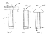
- Figure 5 is a top view of a T-stop.
- Figure 6 is a top view of a straight stop.
- Figure 7 is a top view of a heel stop.
- the present invention is described below in connection with fabricating trusses on a slotted table. Although specific embodiments of the invention are described below, the present invention is not limited to practice in connection with a slotted table or any particular slotted table, nor is the present invention limited to fabricating any particular truss. Rather, the present invention can be utilized with many different tables to fabricate many different types and configurations of trusses.
- the present invention is described herein in connection with a modified form of a laser projection system commercially available from Virtek Vision Corporation, Waterloo, Ontario, Canada, N2L 5J2, which is described in U.S. Patent No. 5,388,318 issued February 14, 1995, which is incorporated herein, in its entirety, by reference. Although a specific laser projection system is referenced, it is contemplated that many other existing laser projection systems can be modified in accordance with the present invention.
- a known laser projection system such as the above-referenced Virtek system is modified to project puck and other jigging hardware alignment or location guides on the table work-surface at predetermined positions corresponding to the desired puck and jigging hardware locations for the truss set-up.
- These projected alignment or location guides are offset from where the members of the truss will be laid-out for assembly.
- the projected alignment or location guides may include various configurations depending upon the shape and size of puck or other jigging hardware to be positioned, and the jigs preferably carry complimentary guide or locator means thereon to facilitate precise alignment of the jigging hardware with the projected guide indicators.
- a cylindrical puck may be quickly and precisely positioned with projected guides which define a single point on the work-surface and complimentary guide means which mark the center of the top surface of the puck, e.g., a notch machined into the puck top surface or a marking.
- a non-cylindrical jig e.g., a T-stop
- the subject laser system may also project all or a portion of the truss image, e.g., an outline of the truss members or connector plates or other assembly information.
- FIG. 1A is a top view of an exemplary slotted top gantry table 100 commonly utilized in truss fabrication
- the table 100 includes adjacent table portions 102 which together define a substantially planar upper surface 104.
- the surface 104 is generally referred to herein as the work-surface of table 104.
- the table portions 102 are spaced apart and form slots 106 (best shown in Figure 1B) in which jigging hardware may be moved and temporarily secured relative to the work-surface 104 for the fabrication of trusses.
- Such slotted tables are well known and are commercially available from, for example, MiTek Industries, Inc. of St. Louis, Missouri.
- the laser projection system 120 includes one or more projectors 124 and a controller 126.
- the controller 126 is preferably operatively connected to receive configuration data regarding the geometry and connections of the truss to be set-up from a second computer (not shown), as more fully described in Patent No. 5,388,318.
- projectors 124 project alignment or location guides 128 upon the work-surface 104.
- the controller 126 controls the location of the guides 128 and may, for example, be a microcomputer.
- FIG 3 is an exploded view of an exemplary puck assembly 150 in accordance with one embodiment of the present invention.
- the puck assembly 150 includes a substantially cylindrical shaped puck 152 having a bore 154 extending there-through, a bolt 156 for extending through the puck bore 154, and a nut 158 for threadedly engaging the bolt 156.
- the puck 152 is preferably fabricated from casehardened steel and coated with a black oxide.
- the bolt 156 includes a head 176 which preferably carries guide means 178 thereon.
- the guide means 178 are shown as cross hairs etched into the upper surface of the bolt-head 176.
- guide means includes, for example, cross hairs, a single dot, a special character, and a special shape, machined into, painted, or otherwise disposed, e.g., adhesively, on head 176.
- the nut 158 for example a T-nut, is sized to be inserted into the slot 106 ( Figure 1B) between adjacent table portions 102. Tightening of the bolt 158 draws the nut 158 into tight contact with an underside surface of the table portions 102 and the puck 152 against the work-surface 104 to maintain the puck assembly 150 in a desired location in the slot 106.
- such known systems would be configured to project alignment or location guides 128 at predetermined locations and orientations off-set from where the truss members are to be laid-out upon the work-surface 104 for assembly.
- the offset locations and or orientations are dependent upon the size and shape of the jig fixture to be used at each given location.
- Such modification of known systems is a straight forward addition to the known software of such projection systems, and such modification may be used by itself or in combination with the projection of the desired truss member configuration on the work-surface.
- jigging hardware sometimes referred to herein as stops or jigs 248, utilized in connection with locating truss members on a work-surface of a slotted table.
- Puck assembly 150 described above is a particular type of jig 248, and although additional specific jigs are described below, it should be understood that many alternative jig configurations could be utilized to secure truss members on the work-surface in accordance with the present invention.
- FIG. 5 is a top view of a T-stop 250.
- the T-stop 250 includes a stop member 252 and a slide 254 extending from the stop member 252.
- Guide means such as indicators 260 are provided on the stop member 252 and may be brought into alignment with complimentary, guide indicators projected by the laser projection system 120.
- Indicators 260 are grooves machined into stop member 252, and the grooves may be painted to have a color distinct from the color of the guide indicators projected by system 120 to facilitate ascertaining when proper alignment is achieved.
- straight stops 300 and heel stops 350 include respective guide means 310 and 360 to facilitate alignment with guide indicators projected by the laser system 120.
- the T-stops 250, straight stops 300, and heel stops 350 are utilized for various purposes in fabricating a truss.
- the T-stops 250 typically are utilized at ends of chords, and the straight stops 300 are utilized along a length of the chord particularly at a splice location.
- Heel stops 350 typically are utilized to locate a heel position of a bottom chord.
- the laser projection system is activated to project laser alignment or location guides 128 on the work-surface 104.
- Each guide 128 represents a location of a puck assembly 150 or other jig or stop fixture 248.
- the puck assemblies 150 are positioned so that the guide means 178 thereon are in alignment with location guides 128.
- the puck assembly 150 is positioned on the work-surface 104 by sliding the puck 152 along the slot 104 until alignment guides 128 and guide means 178 are aligned.
- the puck assembly 150 is then secured by tightening bolt 156.
- the described process is then repeated for each puck assembly 150.
- the stops 248, including stops 250, 300, and 350 are located and aligned with the projected alignment guides 128 and secured.
- the stops 248 are positioned on work-surface 104 so that alignment guides 128 and stop-guide means 260 are aligned. Care must be taken to align all aspect of projected alignment guides 128 and guide means 260 to assure that the stops 248 are correctly positioned and property orientated with respect to the work-surface 104 of table 100.
- the stops 248 are then secured in a manner similar to the puck assemblies 150.
- the truss members are then placed on the work-surface 104 in the area defined by the puck assemblies 150 and the stops 248. Connector plates are then positioned over the truss member interfaces and pressed into the truss members using, for example, a vertical or roller press.
- the above-described system provides the important advantages that the puck and jigging set-up will be exactly in accordance with the engineering specifications for the particular set-up and very little, if any, operator interpretation is required for such set-up, even for complex set-ups.
- an operator can be quickly trained on using the system to provide the desired set-ups.
- the pucks and jigging are securely held in place on the work-surface and, therefore, a particular set-up can be reused without much need for resetting the pucks and jigging.
- use of the subject system will expectedly result in significant cost reductions in the fabrication of factory assembled trusses by reducing the time, labor and training required for multiple or complex truss jig set-ups and, thereby, increasing through put.
Landscapes
- Engineering & Computer Science (AREA)
- Mechanical Engineering (AREA)
- Physics & Mathematics (AREA)
- Optics & Photonics (AREA)
- Life Sciences & Earth Sciences (AREA)
- Forests & Forestry (AREA)
- Conveying And Assembling Of Building Elements In Situ (AREA)
- Adornments (AREA)
- Laser Beam Processing (AREA)
- Fittings On The Vehicle Exterior For Carrying Loads, And Devices For Holding Or Mounting Articles (AREA)
Applications Claiming Priority (2)
| Application Number | Priority Date | Filing Date | Title |
|---|---|---|---|
| US953914 | 1978-10-23 | ||
| US08/953,914 US6317980B2 (en) | 1997-10-20 | 1997-10-20 | Laser jigging system for assembly of trusses and method of use |
Publications (2)
| Publication Number | Publication Date |
|---|---|
| EP0911126A1 true EP0911126A1 (fr) | 1999-04-28 |
| EP0911126B1 EP0911126B1 (fr) | 2003-11-19 |
Family
ID=25494720
Family Applications (1)
| Application Number | Title | Priority Date | Filing Date |
|---|---|---|---|
| EP98307688A Expired - Lifetime EP0911126B1 (fr) | 1997-10-20 | 1998-09-22 | Réglage d'un gabarit a l'aide d'un laser pour la fabrication de fermes et procédé d'utilisation |
Country Status (10)
| Country | Link |
|---|---|
| US (1) | US6317980B2 (fr) |
| EP (1) | EP0911126B1 (fr) |
| AU (1) | AU740365B2 (fr) |
| CA (1) | CA2250601C (fr) |
| DE (1) | DE69819844T2 (fr) |
| DK (1) | DK200000594A (fr) |
| FI (1) | FI115703B (fr) |
| NO (1) | NO321474B1 (fr) |
| WO (1) | WO1999020432A1 (fr) |
| ZA (1) | ZA988900B (fr) |
Cited By (5)
| Publication number | Priority date | Publication date | Assignee | Title |
|---|---|---|---|---|
| EP1815953A2 (fr) | 2006-02-01 | 2007-08-08 | Otto Martin Maschinenbau GmbH & Co. KG | Butée pour une machine de traitement |
| EP1955829A1 (fr) * | 2007-02-09 | 2008-08-13 | Siemens Aktiengesellschaft | Procédé de traitement d'un objet, d'un système ou d'un dispositif et dispositif de traitement associé |
| WO2022219017A1 (fr) * | 2021-04-16 | 2022-10-20 | Dsm Ip Assets B.V. | Formulation de rétinol (ii) |
| WO2022219018A1 (fr) * | 2021-04-16 | 2022-10-20 | Dsm Ip Assets B.V. | Formulation de rétinol (iii) |
| EP4202145A1 (fr) * | 2021-12-21 | 2023-06-28 | Schöck Bauteile GmbH | Procédé et système de fabrication d'une armature d'un élément préfabriqué en béton |
Families Citing this family (30)
| Publication number | Priority date | Publication date | Assignee | Title |
|---|---|---|---|---|
| FR2812671B1 (fr) * | 2000-08-01 | 2006-07-14 | Alstom | Procede de guidage d'un dispositif destine a inserer des elements dans le sol pour la realisation d'un ouvrage et dispositif d'insertion d'au moins un element dans le sol utilisant un tel procede de guidage |
| US7922158B2 (en) * | 2003-02-18 | 2011-04-12 | Truss Industry Production Systems, Inc. | Automatic truss jig setting system |
| US6712347B1 (en) * | 2003-02-18 | 2004-03-30 | Clyde R. Fredrickson | Automatic truss jig setting system |
| US6934607B2 (en) | 2003-03-21 | 2005-08-23 | Fmc Technologies, Inc. | Method and apparatus for visually indexing objects upon a moving surface |
| US7200910B2 (en) * | 2003-10-28 | 2007-04-10 | Delphi Technologies, Inc. | System and method of disposing a substrate in a housing |
| US7241981B2 (en) * | 2004-03-05 | 2007-07-10 | Lap Laser Llc | Systems and methods for displaying images and processing work pieces |
| AU2004201369B2 (en) * | 2004-03-31 | 2007-12-13 | Mitek Holdings, Inc. | Building framework, method for making the same and components used in the framework |
| US20060071383A1 (en) * | 2004-10-05 | 2006-04-06 | Alpine Engineered Products, Inc. | Method and apparatus for placement of movable jig stops |
| US7433796B2 (en) * | 2004-11-16 | 2008-10-07 | The Boeing Company | Methods, systems, and formats for data, such as data used in laser projection of fasteners used in manufacturing |
| US7685701B2 (en) * | 2004-11-18 | 2010-03-30 | Yuichi Hikichi | Method and apparatus for restoring alignment of the support socket in the manufacture of leg prostheses |
| US8782878B2 (en) * | 2005-09-28 | 2014-07-22 | Nikon Metrology Nv | Fastener automation system |
| US20070133216A1 (en) * | 2005-12-08 | 2007-06-14 | Wood Lowell T | Truss fabrication system and method |
| US20080012190A1 (en) * | 2006-04-28 | 2008-01-17 | Mitek Holdings, Inc. | Automated Truss Assembly System |
| US8109493B2 (en) * | 2006-06-08 | 2012-02-07 | Mitek Holdings, Inc. | Automated truss assembly jig setting system |
| WO2008036543A2 (fr) | 2006-09-18 | 2008-03-27 | C.R. Bard, Inc. | Polytétrafluoroéthylène expansé (eptfe) monocouche et anneaux biorésorbables discrets |
| US20080084014A1 (en) * | 2006-10-03 | 2008-04-10 | Mitek Holdings, Inc. | Retrofit Jig System for a Truss Assembly Table |
| WO2008094947A2 (fr) * | 2007-01-29 | 2008-08-07 | Illinois Tool Works, Inc. | Table d'assemblage de ferme de charpente avec système de gabarit de montage automatique |
| US7621053B2 (en) * | 2007-04-13 | 2009-11-24 | Virtek Vision International Inc. | Assembly apparatus |
| US8244392B2 (en) * | 2007-09-28 | 2012-08-14 | Mitek Holdings, Inc. | Automated truss assembly jig setting system |
| MX346859B (es) * | 2011-02-11 | 2017-04-04 | Ops Solutions Llc | Sistema y metodo de montaje guiado por luz. |
| US9113822B2 (en) * | 2011-10-27 | 2015-08-25 | Covidien Lp | Collimated beam metrology systems for in-situ surgical applications |
| EP2590040B1 (fr) * | 2011-11-04 | 2014-05-28 | Nivora IP B.V. | Procédé et dispositif pour aider à la manipulation manuelle d'une pièce de travail pendant l'usinage |
| WO2015006334A1 (fr) | 2013-07-08 | 2015-01-15 | Ops Solutions Llc | Système et procédé de guidage opérationnel avec des lunettes |
| US10006763B2 (en) * | 2014-06-02 | 2018-06-26 | Reel Power Licensing Corp. | Accumulator assembly fixture |
| US10279443B2 (en) | 2014-06-02 | 2019-05-07 | Reel Power Licensing Corp. | Accumulator assembly fixture |
| US20160259324A1 (en) * | 2015-03-05 | 2016-09-08 | Caterpillar Inc. | System and method for guiding deposition of material to form three dimensional structure |
| US20160311062A1 (en) * | 2015-04-21 | 2016-10-27 | Rohr, Inc. | Machining a freely arranged or partially constrained composite part using a laser system |
| US10576588B2 (en) | 2017-09-05 | 2020-03-03 | S L Chasse Welding & Fabricating, Inc. | Fabrication layout device and method |
| US11107236B2 (en) | 2019-04-22 | 2021-08-31 | Dag Michael Peter Hansson | Projected augmented reality interface with pose tracking for directing manual processes |
| USD1002416S1 (en) | 2020-01-14 | 2023-10-24 | Donner Nicholas J | Marker device for use with a CNC layout table |
Citations (6)
| Publication number | Priority date | Publication date | Assignee | Title |
|---|---|---|---|---|
| US3603581A (en) * | 1967-08-23 | 1971-09-07 | Molins Machine Co Ltd | Positioning and securing of workpieces for machining operations |
| US3826188A (en) * | 1972-10-24 | 1974-07-30 | G Eberle | Truss fabricating machine |
| US5388318A (en) * | 1992-10-09 | 1995-02-14 | Laharco, Inc. | Method for defining a template for assembling a structure |
| US5430662A (en) * | 1993-10-22 | 1995-07-04 | Sepa -- Group Ltd. | Laser projection system for truss manufacturing |
| DE19511827C1 (de) * | 1995-03-30 | 1996-04-25 | Seiffert Rolf Wilhelm | Vorrichtung für die Herstellung ebener hölzener Tragwerke |
| WO1997016280A1 (fr) * | 1995-11-02 | 1997-05-09 | Alpine Engineered Products, Inc. | Presse a portique avec reglage de hauteur du rouleau de presse |
Family Cites Families (36)
| Publication number | Priority date | Publication date | Assignee | Title |
|---|---|---|---|---|
| US2212421A (en) | 1937-04-03 | 1940-08-20 | William P Witherow | Assembly table |
| US2919733A (en) | 1956-08-14 | 1960-01-05 | Fullerton Lumber Company | Building frame prefabricating table |
| US2983292A (en) | 1959-01-20 | 1961-05-09 | Pagebar Inc | Clamp table for fabricating a roof truss |
| US3241585A (en) | 1962-10-05 | 1966-03-22 | Automated Building Components | Universal jig assembly |
| US3299920A (en) | 1963-10-30 | 1967-01-24 | Timber Engineering Co | Apparatus for fabricating wood building components |
| US3421751A (en) | 1966-12-23 | 1969-01-14 | Troy Steel Corp | Apparatus for fabricating wood structures |
| US3667379A (en) | 1971-01-11 | 1972-06-06 | Templin Associates Inc | Apparatus for prefabricating wood structures |
| US4084498A (en) | 1976-07-02 | 1978-04-18 | Ottawa Roof Truss, Inc. | Truss making apparatus |
| US4453705A (en) | 1979-09-18 | 1984-06-12 | Mcdonald William D | Mobile wooden truss fabricating apparatus |
| US4286778A (en) | 1979-11-07 | 1981-09-01 | Follmeyer Fred R | Machining fixtures |
| FR2499452A1 (fr) * | 1980-12-22 | 1982-08-13 | Burger Raymond | Procede et dispositif d'assemblage de structures en bois |
| US5148591A (en) * | 1981-05-11 | 1992-09-22 | Sensor Adaptive Machines, Inc. | Vision target based assembly |
| US4379426A (en) | 1981-09-18 | 1983-04-12 | Moehlenpah Industries, Inc. | Truss-fabricating machine |
| US4463786A (en) * | 1982-07-02 | 1984-08-07 | Mellott Hayes R | Timber dapping apparatus |
| US4514901A (en) | 1983-05-23 | 1985-05-07 | Associated Truss Company | Method and apparatus for attaching mounting plates |
| US4627564A (en) | 1984-03-02 | 1986-12-09 | Truswal Systems Corporation | Apparatus for forming a truss assembly |
| US4567821A (en) | 1984-06-08 | 1986-02-04 | Mcdonald William D | Apparatus for assembling wooden trusses and the like |
| US4669184A (en) | 1984-10-29 | 1987-06-02 | Gang-Nail Systems | Building truss fabrication apparatus |
| US4650106A (en) | 1985-02-11 | 1987-03-17 | Branaman David H | Apparatus for aligning and clamping a workpiece |
| US4711437A (en) | 1986-09-02 | 1987-12-08 | Te-Co. | Workpiece securing apparatus for a machine tool |
| US4971413A (en) * | 1987-05-13 | 1990-11-20 | Nikon Corporation | Laser beam depicting apparatus |
| US4875666A (en) * | 1987-06-30 | 1989-10-24 | Hain Leonard P | Clamp for holding work pieces in the formation of trusses |
| US4819475A (en) | 1987-08-04 | 1989-04-11 | Irvello Mario M | Tool for aluminum siding applicators |
| US4998336A (en) | 1989-02-10 | 1991-03-12 | John Papsdorf | Truss fabrication apparatus and method of making a truss |
| US5092028A (en) | 1989-06-29 | 1992-03-03 | Alpine Engineered Products, Inc. | Apparatus for assembly of wood structures |
| US4943038A (en) | 1989-07-17 | 1990-07-24 | Alpine Engineered Products, Inc. | Truss assembly apparatus |
| US5046015A (en) * | 1989-10-18 | 1991-09-03 | Dasher Theodore E | Electronic layout system |
| US5085414A (en) | 1990-04-27 | 1992-02-04 | Weaver Austin S | Jig for forming trusses and the like |
| US5211108A (en) | 1990-11-02 | 1993-05-18 | Truswal Systems Corporation | Truss assembly apparatus with vertically adjustable press roller |
| US5342030A (en) | 1992-11-16 | 1994-08-30 | Multinail Truss System Pty., Ltd. | Truss jigging system |
| US5385339A (en) | 1993-06-01 | 1995-01-31 | Tee-Lok Corporation | Set-up jig for truss table |
| US5569004A (en) * | 1993-06-22 | 1996-10-29 | Optima Industries, Inc. | Machine tool positioning arrangement |
| US5387969A (en) * | 1993-06-22 | 1995-02-07 | Optima Industries, Inc. | Machine tool position measurement employing multiple laser distance measurements |
| US5702095A (en) | 1995-11-02 | 1997-12-30 | Tee-Lok Corporation | Truss table with integrated positioning stops |
| US5837014A (en) * | 1995-11-02 | 1998-11-17 | Tee-Lok Corporation | Truss table with integrated positioning stops |
| US6170163B1 (en) | 1997-02-11 | 2001-01-09 | Virtek Vision Corporation | Method of assembling components of an assembly using a laser image system |
-
1997
- 1997-10-20 US US08/953,914 patent/US6317980B2/en not_active Expired - Fee Related
-
1998
- 1998-01-01 ZA ZA9808900A patent/ZA988900B/xx unknown
- 1998-09-22 DE DE69819844T patent/DE69819844T2/de not_active Expired - Fee Related
- 1998-09-22 AU AU86114/98A patent/AU740365B2/en not_active Ceased
- 1998-09-22 EP EP98307688A patent/EP0911126B1/fr not_active Expired - Lifetime
- 1998-10-15 WO PCT/US1998/021787 patent/WO1999020432A1/fr not_active Ceased
- 1998-10-16 CA CA002250601A patent/CA2250601C/fr not_active Expired - Fee Related
-
2000
- 2000-03-24 NO NO20001568A patent/NO321474B1/no not_active IP Right Cessation
- 2000-04-07 DK DK200000594A patent/DK200000594A/da not_active Application Discontinuation
- 2000-04-17 FI FI20000912A patent/FI115703B/fi active IP Right Grant
Patent Citations (6)
| Publication number | Priority date | Publication date | Assignee | Title |
|---|---|---|---|---|
| US3603581A (en) * | 1967-08-23 | 1971-09-07 | Molins Machine Co Ltd | Positioning and securing of workpieces for machining operations |
| US3826188A (en) * | 1972-10-24 | 1974-07-30 | G Eberle | Truss fabricating machine |
| US5388318A (en) * | 1992-10-09 | 1995-02-14 | Laharco, Inc. | Method for defining a template for assembling a structure |
| US5430662A (en) * | 1993-10-22 | 1995-07-04 | Sepa -- Group Ltd. | Laser projection system for truss manufacturing |
| DE19511827C1 (de) * | 1995-03-30 | 1996-04-25 | Seiffert Rolf Wilhelm | Vorrichtung für die Herstellung ebener hölzener Tragwerke |
| WO1997016280A1 (fr) * | 1995-11-02 | 1997-05-09 | Alpine Engineered Products, Inc. | Presse a portique avec reglage de hauteur du rouleau de presse |
Cited By (7)
| Publication number | Priority date | Publication date | Assignee | Title |
|---|---|---|---|---|
| EP1815953A2 (fr) | 2006-02-01 | 2007-08-08 | Otto Martin Maschinenbau GmbH & Co. KG | Butée pour une machine de traitement |
| EP1815953A3 (fr) * | 2006-02-01 | 2008-06-04 | Otto Martin Maschinenbau GmbH & Co. KG | Butée pour une machine de traitement |
| EP1955829A1 (fr) * | 2007-02-09 | 2008-08-13 | Siemens Aktiengesellschaft | Procédé de traitement d'un objet, d'un système ou d'un dispositif et dispositif de traitement associé |
| WO2022219017A1 (fr) * | 2021-04-16 | 2022-10-20 | Dsm Ip Assets B.V. | Formulation de rétinol (ii) |
| WO2022219018A1 (fr) * | 2021-04-16 | 2022-10-20 | Dsm Ip Assets B.V. | Formulation de rétinol (iii) |
| EP4202145A1 (fr) * | 2021-12-21 | 2023-06-28 | Schöck Bauteile GmbH | Procédé et système de fabrication d'une armature d'un élément préfabriqué en béton |
| EP4202144A1 (fr) * | 2021-12-21 | 2023-06-28 | Schöck Bauteile GmbH | Procédé et système de création d'une armature d'un composant préfabriqué en béton |
Also Published As
| Publication number | Publication date |
|---|---|
| FI20000912L (fi) | 2000-04-17 |
| DE69819844T2 (de) | 2004-04-15 |
| US6317980B2 (en) | 2001-11-20 |
| ZA988900B (en) | 1999-08-19 |
| EP0911126B1 (fr) | 2003-11-19 |
| FI115703B (fi) | 2005-06-30 |
| NO321474B1 (no) | 2006-05-15 |
| US20010015015A1 (en) | 2001-08-23 |
| DE69819844D1 (de) | 2003-12-24 |
| AU740365B2 (en) | 2001-11-01 |
| AU8611498A (en) | 1999-05-06 |
| NO20001568L (no) | 2000-06-16 |
| DK200000594A (da) | 2000-04-07 |
| CA2250601C (fr) | 2004-08-10 |
| CA2250601A1 (fr) | 1999-04-20 |
| NO20001568D0 (no) | 2000-03-24 |
| WO1999020432A1 (fr) | 1999-04-29 |
Similar Documents
| Publication | Publication Date | Title |
|---|---|---|
| US6317980B2 (en) | Laser jigging system for assembly of trusses and method of use | |
| US6170163B1 (en) | Method of assembling components of an assembly using a laser image system | |
| EP3687934B1 (fr) | Dispositif d'alignement et procédé d'installation d'un rail de guidage dans une cage d'un systeme d'ascenseur | |
| CA2185380C (fr) | Table de construction de fermes a butoirs de positionnement integres | |
| DE4307342C2 (de) | Einrichtung zum positionsdefinierten Aufspannen eines Werkstücks am Arbeitsplatz einer Bearbeitungsmaschine | |
| US5810341A (en) | Truss table with integrated positioning stops | |
| EP1784280B1 (fr) | Procede et appareil pour la localisation et l'alignement d'attaches | |
| EP0703038B1 (fr) | Mécanisme de positionnement par une goupille mobile | |
| US5837014A (en) | Truss table with integrated positioning stops | |
| DE68913591T2 (de) | Verfahren und Vorrichtung zum mechanischen Positionieren eines eng anliegenden Werkstücks in einem Behälter. | |
| DE4114284C2 (de) | Vorrichtung zum Behandeln oder Bearbeiten eines Werkstückes, insbesondere einer Schaltkarte | |
| GB2412670A (en) | Framework, e.g. truss, for building and method of making same | |
| EP1165296B1 (fr) | Systeme de gabariage d'armatures | |
| US4922742A (en) | Apparatus for precision forming of sheet metal parts | |
| DE102015211950B4 (de) | Adaptereinrichtung zur Montage eines Objekts auf dem Messtisch eines Koordinatenmessgeräts | |
| GB2029111A (en) | System for locating nailed connector plates for timber joints | |
| CN115743586A (zh) | 组装框架的方法及用于制造具有框架的飞行器外壳的方法 | |
| DE3437125C2 (fr) | ||
| EP4431402B1 (fr) | Dispositif de positionnement et de référencement pour pièces de serrage | |
| JP2547615Y2 (ja) | 平板組立型仕口ブロックの仮組溶接用治具 | |
| WO2001094879A1 (fr) | Procede et dispositif permettant d'aligner un objet par rapport a une image projetee | |
| JPH0351073Y2 (fr) | ||
| EP0176167A1 (fr) | Appareil portatif pour le traitement de métaux | |
| DE3709643A1 (de) | Vorrichtungsplatte | |
| GB2377950A (en) | Forming truss |
Legal Events
| Date | Code | Title | Description |
|---|---|---|---|
| PUAI | Public reference made under article 153(3) epc to a published international application that has entered the european phase |
Free format text: ORIGINAL CODE: 0009012 |
|
| AK | Designated contracting states |
Kind code of ref document: A1 Designated state(s): BE DE FR GB SE |
|
| AX | Request for extension of the european patent |
Free format text: AL;LT;LV;MK;RO;SI |
|
| 17P | Request for examination filed |
Effective date: 19991018 |
|
| AKX | Designation fees paid |
Free format text: BE DE FR GB SE |
|
| 17Q | First examination report despatched |
Effective date: 20020731 |
|
| GRAH | Despatch of communication of intention to grant a patent |
Free format text: ORIGINAL CODE: EPIDOS IGRA |
|
| GRAS | Grant fee paid |
Free format text: ORIGINAL CODE: EPIDOSNIGR3 |
|
| GRAA | (expected) grant |
Free format text: ORIGINAL CODE: 0009210 |
|
| AK | Designated contracting states |
Kind code of ref document: B1 Designated state(s): BE DE FR GB SE |
|
| REG | Reference to a national code |
Ref country code: GB Ref legal event code: FG4D |
|
| REG | Reference to a national code |
Ref country code: SE Ref legal event code: TRGR |
|
| REF | Corresponds to: |
Ref document number: 69819844 Country of ref document: DE Date of ref document: 20031224 Kind code of ref document: P |
|
| ET | Fr: translation filed | ||
| PLBE | No opposition filed within time limit |
Free format text: ORIGINAL CODE: 0009261 |
|
| STAA | Information on the status of an ep patent application or granted ep patent |
Free format text: STATUS: NO OPPOSITION FILED WITHIN TIME LIMIT |
|
| 26N | No opposition filed |
Effective date: 20040820 |
|
| PGFP | Annual fee paid to national office [announced via postgrant information from national office to epo] |
Ref country code: FR Payment date: 20080917 Year of fee payment: 11 |
|
| PGFP | Annual fee paid to national office [announced via postgrant information from national office to epo] |
Ref country code: GB Payment date: 20080929 Year of fee payment: 11 |
|
| PGFP | Annual fee paid to national office [announced via postgrant information from national office to epo] |
Ref country code: DE Payment date: 20081031 Year of fee payment: 11 |
|
| PGFP | Annual fee paid to national office [announced via postgrant information from national office to epo] |
Ref country code: BE Payment date: 20081009 Year of fee payment: 11 Ref country code: SE Payment date: 20080929 Year of fee payment: 11 |
|
| BERE | Be: lapsed |
Owner name: *MITEK HOLDINGS INC. Effective date: 20090930 |
|
| EUG | Se: european patent has lapsed | ||
| GBPC | Gb: european patent ceased through non-payment of renewal fee |
Effective date: 20090922 |
|
| REG | Reference to a national code |
Ref country code: FR Ref legal event code: ST Effective date: 20100531 |
|
| PG25 | Lapsed in a contracting state [announced via postgrant information from national office to epo] |
Ref country code: FR Free format text: LAPSE BECAUSE OF NON-PAYMENT OF DUE FEES Effective date: 20090930 Ref country code: DE Free format text: LAPSE BECAUSE OF NON-PAYMENT OF DUE FEES Effective date: 20100401 |
|
| PG25 | Lapsed in a contracting state [announced via postgrant information from national office to epo] |
Ref country code: BE Free format text: LAPSE BECAUSE OF NON-PAYMENT OF DUE FEES Effective date: 20090930 |
|
| PG25 | Lapsed in a contracting state [announced via postgrant information from national office to epo] |
Ref country code: GB Free format text: LAPSE BECAUSE OF NON-PAYMENT OF DUE FEES Effective date: 20090922 |
|
| PG25 | Lapsed in a contracting state [announced via postgrant information from national office to epo] |
Ref country code: SE Free format text: LAPSE BECAUSE OF NON-PAYMENT OF DUE FEES Effective date: 20090923 |