EP0911143A1 - Verfahren zum Formen eines im wesentlichen zylindrischen hohlen Verbundgegenstandes, Formwerkzeug zu dessen Herstellung und damit hergestellter Gegenstand - Google Patents
Verfahren zum Formen eines im wesentlichen zylindrischen hohlen Verbundgegenstandes, Formwerkzeug zu dessen Herstellung und damit hergestellter Gegenstand Download PDFInfo
- Publication number
- EP0911143A1 EP0911143A1 EP98420192A EP98420192A EP0911143A1 EP 0911143 A1 EP0911143 A1 EP 0911143A1 EP 98420192 A EP98420192 A EP 98420192A EP 98420192 A EP98420192 A EP 98420192A EP 0911143 A1 EP0911143 A1 EP 0911143A1
- Authority
- EP
- European Patent Office
- Prior art keywords
- mold
- tube
- shoe
- resin
- sleeve
- Prior art date
- Legal status (The legal status is an assumption and is not a legal conclusion. Google has not performed a legal analysis and makes no representation as to the accuracy of the status listed.)
- Granted
Links
- 238000000465 moulding Methods 0.000 title claims abstract description 16
- 238000000034 method Methods 0.000 title claims description 19
- 238000004519 manufacturing process Methods 0.000 title claims description 9
- 239000002131 composite material Substances 0.000 title claims description 7
- 229920005989 resin Polymers 0.000 claims abstract description 25
- 239000011347 resin Substances 0.000 claims abstract description 25
- 239000004744 fabric Substances 0.000 claims abstract description 20
- 239000012783 reinforcing fiber Substances 0.000 claims abstract description 13
- 239000004917 carbon fiber Substances 0.000 claims abstract description 5
- 239000004760 aramid Substances 0.000 claims abstract description 4
- 229920006231 aramid fiber Polymers 0.000 claims abstract description 3
- 239000003365 glass fiber Substances 0.000 claims abstract description 3
- 229920001187 thermosetting polymer Polymers 0.000 claims description 9
- 238000006116 polymerization reaction Methods 0.000 claims description 5
- 238000010438 heat treatment Methods 0.000 claims description 4
- 210000002105 tongue Anatomy 0.000 claims description 3
- 238000004804 winding Methods 0.000 claims description 3
- 239000003822 epoxy resin Substances 0.000 claims description 2
- 229920000647 polyepoxide Polymers 0.000 claims description 2
- OKTJSMMVPCPJKN-UHFFFAOYSA-N Carbon Chemical compound [C] OKTJSMMVPCPJKN-UHFFFAOYSA-N 0.000 claims 1
- 229910052799 carbon Inorganic materials 0.000 claims 1
- 229920000049 Carbon (fiber) Polymers 0.000 abstract description 4
- 239000004593 Epoxy Substances 0.000 abstract description 2
- 230000001681 protective effect Effects 0.000 abstract description 2
- 230000002787 reinforcement Effects 0.000 abstract 1
- 230000003014 reinforcing effect Effects 0.000 abstract 1
- 229920001169 thermoplastic Polymers 0.000 abstract 1
- 239000004416 thermosoftening plastic Substances 0.000 abstract 1
- 238000002347 injection Methods 0.000 description 8
- 239000007924 injection Substances 0.000 description 8
- 210000001519 tissue Anatomy 0.000 description 5
- 238000009434 installation Methods 0.000 description 4
- 208000031968 Cadaver Diseases 0.000 description 3
- 238000004891 communication Methods 0.000 description 2
- 238000009826 distribution Methods 0.000 description 2
- 238000000605 extraction Methods 0.000 description 2
- 210000000003 hoof Anatomy 0.000 description 2
- 239000000463 material Substances 0.000 description 2
- 238000004017 vitrification Methods 0.000 description 2
- KWGRBVOPPLSCSI-WPRPVWTQSA-N (-)-ephedrine Chemical compound CN[C@@H](C)[C@H](O)C1=CC=CC=C1 KWGRBVOPPLSCSI-WPRPVWTQSA-N 0.000 description 1
- 241000135309 Processus Species 0.000 description 1
- 229920003235 aromatic polyamide Polymers 0.000 description 1
- 238000004140 cleaning Methods 0.000 description 1
- 230000003750 conditioning effect Effects 0.000 description 1
- 238000010276 construction Methods 0.000 description 1
- 238000005553 drilling Methods 0.000 description 1
- 239000011152 fibreglass Substances 0.000 description 1
- 239000012530 fluid Substances 0.000 description 1
- 239000011521 glass Substances 0.000 description 1
- 238000003754 machining Methods 0.000 description 1
- 230000002093 peripheral effect Effects 0.000 description 1
- 239000004033 plastic Substances 0.000 description 1
- 230000000284 resting effect Effects 0.000 description 1
- 238000007789 sealing Methods 0.000 description 1
- 230000003313 weakening effect Effects 0.000 description 1
Images


Classifications
-
- B—PERFORMING OPERATIONS; TRANSPORTING
- B29—WORKING OF PLASTICS; WORKING OF SUBSTANCES IN A PLASTIC STATE IN GENERAL
- B29C—SHAPING OR JOINING OF PLASTICS; SHAPING OF MATERIAL IN A PLASTIC STATE, NOT OTHERWISE PROVIDED FOR; AFTER-TREATMENT OF THE SHAPED PRODUCTS, e.g. REPAIRING
- B29C70/00—Shaping composites, i.e. plastics material comprising reinforcements, fillers or preformed parts, e.g. inserts
- B29C70/04—Shaping composites, i.e. plastics material comprising reinforcements, fillers or preformed parts, e.g. inserts comprising reinforcements only, e.g. self-reinforcing plastics
- B29C70/28—Shaping operations therefor
- B29C70/40—Shaping or impregnating by compression not applied
- B29C70/42—Shaping or impregnating by compression not applied for producing articles of definite length, i.e. discrete articles
- B29C70/44—Shaping or impregnating by compression not applied for producing articles of definite length, i.e. discrete articles using isostatic pressure, e.g. pressure difference-moulding, vacuum bag-moulding, autoclave-moulding or expanding rubber-moulding
- B29C70/446—Moulding structures having an axis of symmetry or at least one channel, e.g. tubular structures, frames
Definitions
- the invention relates to a molding process and a mold. for the production of a generally cylindrical part with hollow profile in composite material.
- the invention also relates to a part produced thanks to the implementation of this process or this mold.
- cylindrical part any part whose outer surface is formed, on its largest part, of parallel generators whatever the shape of its section which can be circular, but also oval or polygonal.
- the preforming of the fabric tube of fiberglass allows the introduction of it inside of the mold while it has an opening whose cross section is of diameter substantially equal to that of the finished part.
- the fabric reinforcing fibers is made from carbon fibers, glass or aramid, while the resin is a resin epoxy.
- the invention also relates to a part produced according to the previously described process or thanks to the implementation of the previously described mold.
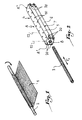
- a fabric 1 of carbon fibers is wound on a mandrel 2 so as to form a hollow tube 3.
- glass or aramid fibers could be used in place of carbon fibers.
- the fabric strip 1 When the fabric strip 1 is in place on the mandrel 2, it is introduced into an oven heated to a temperature comprised between 100 and 150 ° C, preferably of the order of 120 ° C, for between 10 and 45 minutes, for example from around 30 minutes.
- Figure 2 also shows the part central A of a mold 4, this central part being constituted of two elongated bodies 5 and 6 resting against each other thanks to a contact surface 7.
- the bodies 5 and 6 define between them a generally cylindrical interior volume 8 in the part A.
- the diameter of the mandrel 2 is chosen to be slightly smaller than that of the volume 8, so that the tube 3, once produced, can be introduced in the direction of the arrow F 1 in FIG. 2 inside the volume 8.
- the bodies 5 and 6 are assembled together by means of holes 10 perpendicular to the main direction of the volume 8 and intended to receive bolts 11 or pawns of centering 12.
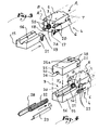
- the body 6 comprises two holes 17 and 18 overall parallel to volume 8 and intended to receive pawns of centering, only one of which is visible in Figure 3 with the reference 19, which allow to effectively position the shoe 15 relative to the body 6.
- articulated fasteners 20 intended to cooperate with hooks 21 fixed on each side of the shoe 15.
- a sleeve 22 formed of a woven reinforcing fiber fabric circularly or "sock". This sleeve may also consist of several individual sleeves or "socks" arranged one inside the other.
- the sleeve 22 is intended to constitute the end of the part to be produced using the mold of the invention.
- the sleeve 22 is placed in the cavity 16 according to the arrow F 2 in FIG. 4.
- a second shoe 25 is mounted on shoe 16 in contact with the end of the body 5 and covers the sleeve 22.
- the shoe 25 is provided with an imprint 26 whose geometry is same type as that of imprint 16.
- tongues 28 and 29 are provided to be arranged on either side of the sleeve 22 at the joint plane 30 of the shoes 15 and 25 before the shoe 25 is put in place. These tongues 28 and 29 prevent the sleeve 22 from being pinched between the shoes 15 and 25 during the installation of the shoe 25, represented by the arrow F 3 in FIG. 4. As soon as the shoe 25 is in place, the tabs 28 and 29 can be removed.
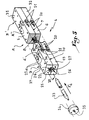
- a second set of shoes 31 and 32 can be disposed at the second end A "of the part central A, so as to constitute a second end part B 'of the mold 4. This is shown in FIG. 5.
- a bladder intended to be engaged inside the sleeve 22, the tube 3 and the corresponding sleeve disposed in the end part B '.
- This bladder 33 is intended to be supplied with pressurized air in a later stage of the manufacturing process so as to compress the tube 3 and the sleeves of the tube of the sleeve 22 towards the peripheral surfaces of the housings 8, 27 or equivalent.
- the bladder 33 is put in place in the direction of the arrow F 4 in FIG. 5. It should however be noted that the bladder 33 could be put in place at any time after the tube 3 has been placed in the volume 8, or even in the tube 3 before it is placed in the volume 8. It can in particular be provided for it to be introduced into the sleeve (s) 22 and into the tube 3 before the shoe 25 is fixed and / or tightened.
- the bladder 33 is placed after the sleeves 22, so that it does not interfere with their positioning.
- a plug 34 is provided to close the outlet of the housing 27 when the bladder 33 and the sleeve 22 are in square.
- This plug 34 is provided with a central orifice 35, the function will be explained below.
- pins 36 and pins 37 are provided perpendicular to the axis of the tube 3 to assemble the shoes 15 and 25.
- Pins 38 allow also the positioning of the shoe 25 relative to the body 5 of the central part A.
- the pins 38 are similar to the pins 19 used for the shoe 15.
- the pins 19 and 38 are maneuverable thanks to notches 15 a and 25 a provided on the external surfaces of the shoes 15 and 25 to exert on the end of the pins 19 and 38 a force directed towards the bodies 5 and 6.
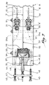
- a corner 40 is provided for closing the orifice 35 of the plug 34.
- the wedge 40 has an outer surface in the form of a truncated cone.
- the inner surface of orifice 35 is also shaped like trunk of cone.
- the corner 40 is carried by a plate 41 provided two screws 42 and 43 for fixing to the plug 34 which includes two internal threads 44 and 45 for receiving the screws 42 and 43. understands that the tightening of screws 42 and 43 in threads 44 and 45 makes it possible to obtain a great seal of the obturation of the orifice 35 through the corner 40.
- the corner 40 is provided with an axial bore 46 in communication with a compressed air supply line 47. So, as long as we have taken the precaution to make the bladder 33 outside the orifice 35, as is shown in Figure 7, it is possible to inject air under pressure inside the screw 33, thanks to the wedge 40.
- a second plug is provided on the side of the end B 'of the mold 4 of the invention.
- this cap we can foresee a drilling allowing to put in communication the interior volume of the mold and a tube 50 for extracting the air included in the interior volume of the mold which is shown in Figure 8.
- the tube 50 is connected to a vacuum pump 51 of a type known per se.
- a line 52 is provided for supplying the interior volume of the mold 4 from a unit C for conditioning the thermosetting resin for injection around the bladder 33, as shown by the arrows F 5 in FIG. 6.
- This unit comprises an agitator 53, the blade of which is arranged inside a pressure pot 54 supplied with compressed air by means of a pipe 55 from a source not shown.
- line 52 is thermally insulated from the atmosphere ambient. Heating at suitable temperature takes place indoors of the pot 54.
- the cap 34 is provided with a second orifice 57 for injecting the thermosetting resin, such as in particular an epoxy resin, inside the mold 4.
- the injection takes place through one of the ends B while the depression of the interior of the mold by the pump 51 takes place at the other end B '.
- the injection is scheduled for temperature between 80 and 160 °, that is to say at a temperature at which the resin is sufficiently fluid to evenly distributed in the interior volume of the mold, while the bladder is dilated by air injection compressed through feed line 47.
Landscapes
- Chemical & Material Sciences (AREA)
- Engineering & Computer Science (AREA)
- Composite Materials (AREA)
- Mechanical Engineering (AREA)
- Moulds For Moulding Plastics Or The Like (AREA)
- Injection Moulding Of Plastics Or The Like (AREA)
Applications Claiming Priority (2)
| Application Number | Priority Date | Filing Date | Title |
|---|---|---|---|
| FR9713396A FR2769866B1 (fr) | 1997-10-20 | 1997-10-20 | Procede de moulage, moule de fabrication d'une piece globalement cylindrique a profil creux en matiere composite et piece obtenue grace a ce procede |
| FR9713396 | 1997-10-20 |
Publications (2)
| Publication Number | Publication Date |
|---|---|
| EP0911143A1 true EP0911143A1 (de) | 1999-04-28 |
| EP0911143B1 EP0911143B1 (de) | 2003-03-05 |
Family
ID=9512643
Family Applications (1)
| Application Number | Title | Priority Date | Filing Date |
|---|---|---|---|
| EP19980420192 Expired - Lifetime EP0911143B1 (de) | 1997-10-20 | 1998-10-19 | Verfahren zum Formen eines im wesentlichen zylindrischen hohlen Verbundgegenstandes und Formwerkzeug zu dessen Herstellung |
Country Status (3)
| Country | Link |
|---|---|
| EP (1) | EP0911143B1 (de) |
| DE (1) | DE69811816T2 (de) |
| FR (1) | FR2769866B1 (de) |
Cited By (4)
| Publication number | Priority date | Publication date | Assignee | Title |
|---|---|---|---|---|
| WO2009074419A1 (de) * | 2007-12-13 | 2009-06-18 | Airbus Operations Gmbh | Verfahren und vorrichtung zur herstellung röhrenförmiger strukturbauteile |
| US8043457B2 (en) | 2007-06-06 | 2011-10-25 | Airbus Operations Limited | Fibre placement tool |
| US10247227B2 (en) | 2011-06-22 | 2019-04-02 | Mt Aerospace Ag | Component for absorbing and/or transmitting mechanical forces and/or moments, method for producing same and use thereof |
| EP4010160A4 (de) * | 2019-08-07 | 2023-05-03 | Saab Ab | Formwerkzeuganordnung |
Families Citing this family (4)
| Publication number | Priority date | Publication date | Assignee | Title |
|---|---|---|---|---|
| FR2862112B1 (fr) * | 2003-11-06 | 2007-01-26 | Sarma | Procede de fabrication d'un organe formant au moins une rotule et organe ainsi realise |
| DE102008016616B4 (de) | 2008-04-01 | 2019-01-17 | Dr. Ing. H.C. F. Porsche Aktiengesellschaft | Verfahren zum Herstellen eines hohlen Faserverbundbauteils |
| DE102012104370B4 (de) * | 2012-05-21 | 2016-02-18 | Cotesa Gmbh | Verfahren zur Herstellung eines Hohlkörpers aus faserverstärktem Kunststoff |
| DE102013220990A1 (de) | 2013-10-16 | 2015-04-30 | Bayerische Motoren Werke Aktiengesellschaft | Blasschlauch für Innendruck-Spritzgießen |
Citations (5)
| Publication number | Priority date | Publication date | Assignee | Title |
|---|---|---|---|---|
| US2815534A (en) * | 1954-07-12 | 1957-12-10 | Ising George Earl | Process for making a closed one-piece reinforced plastic tank |
| GB1453936A (en) * | 1973-10-19 | 1976-10-27 | Mcdonald R H Russell H E | Method of moulding reinforced plastic materials |
| FR2532581A1 (fr) * | 1982-09-07 | 1984-03-09 | Fischer Gmbh | Corps creux tubulaire pour la transmission des efforts de compression, de traction et de torsion, procede pour sa fabrication et dispositif pour l'application du procede decrit |
| FR2602458A1 (fr) * | 1986-08-08 | 1988-02-12 | Aerazur Efa | Procede de realisation d'un tube composite et tube ainsi obtenu |
| US5217555A (en) * | 1991-12-09 | 1993-06-08 | Lockheed Corporation | Process for making hollow tubular structural members with integral end attachment fittings |
-
1997
- 1997-10-20 FR FR9713396A patent/FR2769866B1/fr not_active Expired - Fee Related
-
1998
- 1998-10-19 EP EP19980420192 patent/EP0911143B1/de not_active Expired - Lifetime
- 1998-10-19 DE DE69811816T patent/DE69811816T2/de not_active Expired - Lifetime
Patent Citations (5)
| Publication number | Priority date | Publication date | Assignee | Title |
|---|---|---|---|---|
| US2815534A (en) * | 1954-07-12 | 1957-12-10 | Ising George Earl | Process for making a closed one-piece reinforced plastic tank |
| GB1453936A (en) * | 1973-10-19 | 1976-10-27 | Mcdonald R H Russell H E | Method of moulding reinforced plastic materials |
| FR2532581A1 (fr) * | 1982-09-07 | 1984-03-09 | Fischer Gmbh | Corps creux tubulaire pour la transmission des efforts de compression, de traction et de torsion, procede pour sa fabrication et dispositif pour l'application du procede decrit |
| FR2602458A1 (fr) * | 1986-08-08 | 1988-02-12 | Aerazur Efa | Procede de realisation d'un tube composite et tube ainsi obtenu |
| US5217555A (en) * | 1991-12-09 | 1993-06-08 | Lockheed Corporation | Process for making hollow tubular structural members with integral end attachment fittings |
Cited By (7)
| Publication number | Priority date | Publication date | Assignee | Title |
|---|---|---|---|---|
| US8043457B2 (en) | 2007-06-06 | 2011-10-25 | Airbus Operations Limited | Fibre placement tool |
| US8490269B2 (en) | 2007-06-06 | 2013-07-23 | Airbus Operations Limited | Fibre placement tool |
| WO2009074419A1 (de) * | 2007-12-13 | 2009-06-18 | Airbus Operations Gmbh | Verfahren und vorrichtung zur herstellung röhrenförmiger strukturbauteile |
| RU2488488C2 (ru) * | 2007-12-13 | 2013-07-27 | Эйрбас Оператионс Гмбх | Способ и устройство для производства цилиндрических конструктивных компонентов |
| US9180628B2 (en) | 2007-12-13 | 2015-11-10 | Airbus Operations Gmbh | Method and device for the production of tubular structural components |
| US10247227B2 (en) | 2011-06-22 | 2019-04-02 | Mt Aerospace Ag | Component for absorbing and/or transmitting mechanical forces and/or moments, method for producing same and use thereof |
| EP4010160A4 (de) * | 2019-08-07 | 2023-05-03 | Saab Ab | Formwerkzeuganordnung |
Also Published As
| Publication number | Publication date |
|---|---|
| EP0911143B1 (de) | 2003-03-05 |
| FR2769866B1 (fr) | 2000-01-14 |
| FR2769866A1 (fr) | 1999-04-23 |
| DE69811816D1 (de) | 2003-04-10 |
| DE69811816T2 (de) | 2004-02-05 |
Similar Documents
| Publication | Publication Date | Title |
|---|---|---|
| EP0198774B1 (de) | Form zum Herstellen von drei konzentrische Elemente aufweisenden Gegenständen | |
| FR2653743A1 (fr) | Sous-ensemble de pale d'un propulseur et son procede de fabrication. | |
| EP0770463B1 (de) | Verfahren zum Formen von faserverstärkten, hochfesten, langgestreckten Gegenständen | |
| FR2760681A1 (fr) | Procede de fabrication d'une piece de grandes dimensions en materiau composite et pale d'helice, en particulier d'eolienne, fabriquee selon ce procede | |
| EP0911143B1 (de) | Verfahren zum Formen eines im wesentlichen zylindrischen hohlen Verbundgegenstandes und Formwerkzeug zu dessen Herstellung | |
| EP0010024B1 (de) | Verfahren zur Herstellung von Röhren aus Gewebe, das mit Kunstharz imprägniert ist, und so hergestellte Röhren | |
| FR3026980A1 (fr) | Procede d'immobilisation d'une preforme dans un moule | |
| EP0033275A1 (de) | Verfahren zur Herstellung eines biegsamen und verdrehbaren Elements und nach diesem Verfahren erhaltene Elemente | |
| EP0021902A1 (de) | Verfahren zur Befestigung von Isolierstangen in Aufhängungsarmaturen und Vorrichtung zu dessen Ausführung | |
| FR2917666A1 (fr) | Roue a rayon demontable en materiau composite | |
| WO2018146428A1 (fr) | Regulateur d'injection de resine, circuit d'injection de resine et procedes associes | |
| EP0013040A1 (de) | Verfahren und Vorrichtung zum Formen von Kunststoff-Kupplungen | |
| EP0780213B1 (de) | Verfahren zur Herstellung eines Gegenstandes aus Verbundwerkstoff durch Transfer-Spritzgiessen von Kunstharz (R.T.M.) und dadurch hergestellter Gegenstand | |
| FR2518415A1 (fr) | Procede de fabrication d'un cadre de raquette | |
| FR2617864A1 (fr) | Receptacle de confinement d'un liquide biologique | |
| EP0081834B1 (de) | Leichtgebauter Ski mit Kern und sein Herstellungsverfahren | |
| WO1994024595A1 (fr) | Installation et procede de fabrication d'un cable a fibre optique | |
| FR2631581A1 (fr) | Procede de revetement d'un flacon par une pellicule plastique, machine d'injection pour la mise en oeuvre du procede et flacon revetu par le procede | |
| EP1448349B1 (de) | Verfahren und vorrichtung zum überziehen von rohrförmigen gegenständen mittels eines kunststoff-pressformverfahrens | |
| FR2803558A1 (fr) | Procede pour la realisation et la mise en place d'une enveloppe en elastomere autour d'un corps plein ou creux | |
| FR2750640A1 (fr) | Procede de fabrication d'un produit en matiere plastique renforcee de fibres | |
| EP0712709B1 (de) | Verfahren zur Herstellung eines umgossenen Verschleissanzeigers für Bremsbelag | |
| EP0724942A1 (de) | Verfahren und Formen zur Herstellung von Kunststoff-Verbundgegenständen mit einer Oberflächenschicht und dadurch hergestellte Gegenstände | |
| FR2682063A1 (fr) | Systeme de filieres pour le moulage par injection d'elements de grande surface en matiere plastique avec des cavites fermees. | |
| WO2023169994A1 (fr) | Connecteur de liaison destine a lier entre eux des premier et second elements d'un ouvrage |
Legal Events
| Date | Code | Title | Description |
|---|---|---|---|
| PUAI | Public reference made under article 153(3) epc to a published international application that has entered the european phase |
Free format text: ORIGINAL CODE: 0009012 |
|
| AK | Designated contracting states |
Kind code of ref document: A1 Designated state(s): DE FR GB IT |
|
| AX | Request for extension of the european patent |
Free format text: AL;LT;LV;MK;RO;SI |
|
| 17P | Request for examination filed |
Effective date: 19990820 |
|
| AKX | Designation fees paid |
Free format text: DE FR GB IT |
|
| 17Q | First examination report despatched |
Effective date: 20000519 |
|
| RTI1 | Title (correction) |
Free format text: PROCESS FOR MOULDING A SUBSTANTIALLY CYLINDRICAL HOLLOW ARTICLE MADE OF COMPOSITE MATERIAL AND MOULD FOR ITS MANUFACTURE. |
|
| RTI1 | Title (correction) |
Free format text: PROCESS FOR MOULDING A SUBSTANTIALLY CYLINDRICAL HOLLOW ARTICLE MADE OF COMPOSITE MATERIAL AND MOULD FOR ITS MANUFACTURE. |
|
| GRAH | Despatch of communication of intention to grant a patent |
Free format text: ORIGINAL CODE: EPIDOS IGRA |
|
| RTI1 | Title (correction) |
Free format text: PROCESS FOR MOULDING A SUBSTANTIALLY CYLINDRICAL HOLLOW ARTICLE MADE OF COMPOSITE MATERIAL AND MOULD FOR ITS MANUFACTURE |
|
| GRAH | Despatch of communication of intention to grant a patent |
Free format text: ORIGINAL CODE: EPIDOS IGRA |
|
| GRAA | (expected) grant |
Free format text: ORIGINAL CODE: 0009210 |
|
| AK | Designated contracting states |
Designated state(s): DE FR GB IT |
|
| REG | Reference to a national code |
Ref country code: GB Ref legal event code: FG4D Free format text: NOT ENGLISH |
|
| REF | Corresponds to: |
Ref document number: 69811816 Country of ref document: DE Date of ref document: 20030410 Kind code of ref document: P |
|
| GBT | Gb: translation of ep patent filed (gb section 77(6)(a)/1977) | ||
| PLBE | No opposition filed within time limit |
Free format text: ORIGINAL CODE: 0009261 |
|
| STAA | Information on the status of an ep patent application or granted ep patent |
Free format text: STATUS: NO OPPOSITION FILED WITHIN TIME LIMIT |
|
| 26N | No opposition filed |
Effective date: 20031208 |
|
| REG | Reference to a national code |
Ref country code: FR Ref legal event code: PLFP Year of fee payment: 18 |
|
| REG | Reference to a national code |
Ref country code: FR Ref legal event code: PLFP Year of fee payment: 19 |
|
| REG | Reference to a national code |
Ref country code: FR Ref legal event code: PLFP Year of fee payment: 20 |
|
| PGFP | Annual fee paid to national office [announced via postgrant information from national office to epo] |
Ref country code: FR Payment date: 20171031 Year of fee payment: 20 |
|
| PGFP | Annual fee paid to national office [announced via postgrant information from national office to epo] |
Ref country code: GB Payment date: 20171101 Year of fee payment: 20 Ref country code: IT Payment date: 20171024 Year of fee payment: 20 |
|
| PGFP | Annual fee paid to national office [announced via postgrant information from national office to epo] |
Ref country code: DE Payment date: 20171229 Year of fee payment: 20 |
|
| REG | Reference to a national code |
Ref country code: DE Ref legal event code: R071 Ref document number: 69811816 Country of ref document: DE |
|
| REG | Reference to a national code |
Ref country code: GB Ref legal event code: PE20 Expiry date: 20181018 |
|
| PG25 | Lapsed in a contracting state [announced via postgrant information from national office to epo] |
Ref country code: GB Free format text: LAPSE BECAUSE OF EXPIRATION OF PROTECTION Effective date: 20181018 |