EP0911205B1 - Steuerungssystem für die Grenzkraft eines Differentials in einem vierradangetriebenen Fahrzeug - Google Patents
Steuerungssystem für die Grenzkraft eines Differentials in einem vierradangetriebenen Fahrzeug Download PDFInfo
- Publication number
- EP0911205B1 EP0911205B1 EP98119783A EP98119783A EP0911205B1 EP 0911205 B1 EP0911205 B1 EP 0911205B1 EP 98119783 A EP98119783 A EP 98119783A EP 98119783 A EP98119783 A EP 98119783A EP 0911205 B1 EP0911205 B1 EP 0911205B1
- Authority
- EP
- European Patent Office
- Prior art keywords
- differential limiting
- force
- braking force
- differential
- wheel
- Prior art date
- Legal status (The legal status is an assumption and is not a legal conclusion. Google has not performed a legal analysis and makes no representation as to the accuracy of the status listed.)
- Expired - Lifetime
Links
Images




Classifications
-
- B—PERFORMING OPERATIONS; TRANSPORTING
- B60—VEHICLES IN GENERAL
- B60K—ARRANGEMENT OR MOUNTING OF PROPULSION UNITS OR OF TRANSMISSIONS IN VEHICLES; ARRANGEMENT OR MOUNTING OF PLURAL DIVERSE PRIME-MOVERS IN VEHICLES; AUXILIARY DRIVES FOR VEHICLES; INSTRUMENTATION OR DASHBOARDS FOR VEHICLES; ARRANGEMENTS IN CONNECTION WITH COOLING, AIR INTAKE, GAS EXHAUST OR FUEL SUPPLY OF PROPULSION UNITS IN VEHICLES
- B60K23/00—Arrangement or mounting of control devices for vehicle transmissions, or parts thereof, not otherwise provided for
- B60K23/08—Arrangement or mounting of control devices for vehicle transmissions, or parts thereof, not otherwise provided for for changing number of driven wheels, for switching from driving one axle to driving two or more axles
- B60K23/0808—Arrangement or mounting of control devices for vehicle transmissions, or parts thereof, not otherwise provided for for changing number of driven wheels, for switching from driving one axle to driving two or more axles for varying torque distribution between driven axles, e.g. by transfer clutch
-
- B—PERFORMING OPERATIONS; TRANSPORTING
- B60—VEHICLES IN GENERAL
- B60K—ARRANGEMENT OR MOUNTING OF PROPULSION UNITS OR OF TRANSMISSIONS IN VEHICLES; ARRANGEMENT OR MOUNTING OF PLURAL DIVERSE PRIME-MOVERS IN VEHICLES; AUXILIARY DRIVES FOR VEHICLES; INSTRUMENTATION OR DASHBOARDS FOR VEHICLES; ARRANGEMENTS IN CONNECTION WITH COOLING, AIR INTAKE, GAS EXHAUST OR FUEL SUPPLY OF PROPULSION UNITS IN VEHICLES
- B60K28/00—Safety devices for propulsion-unit control, specially adapted for, or arranged in, vehicles, e.g. preventing fuel supply or ignition in the event of potentially dangerous conditions
- B60K28/10—Safety devices for propulsion-unit control, specially adapted for, or arranged in, vehicles, e.g. preventing fuel supply or ignition in the event of potentially dangerous conditions responsive to conditions relating to the vehicle
- B60K28/16—Safety devices for propulsion-unit control, specially adapted for, or arranged in, vehicles, e.g. preventing fuel supply or ignition in the event of potentially dangerous conditions responsive to conditions relating to the vehicle responsive to, or preventing, spinning or skidding of wheels
- B60K28/165—Safety devices for propulsion-unit control, specially adapted for, or arranged in, vehicles, e.g. preventing fuel supply or ignition in the event of potentially dangerous conditions responsive to conditions relating to the vehicle responsive to, or preventing, spinning or skidding of wheels acting on elements of the vehicle drive train other than the propulsion unit and brakes, e.g. transmission, clutch, differential
-
- B—PERFORMING OPERATIONS; TRANSPORTING
- B60—VEHICLES IN GENERAL
- B60T—VEHICLE BRAKE CONTROL SYSTEMS OR PARTS THEREOF; BRAKE CONTROL SYSTEMS OR PARTS THEREOF, IN GENERAL; ARRANGEMENT OF BRAKING ELEMENTS ON VEHICLES IN GENERAL; PORTABLE DEVICES FOR PREVENTING UNWANTED MOVEMENT OF VEHICLES; VEHICLE MODIFICATIONS TO FACILITATE COOLING OF BRAKES
- B60T8/00—Arrangements for adjusting wheel-braking force to meet varying vehicular or ground-surface conditions, e.g. limiting or varying distribution of braking force
- B60T8/17—Using electrical or electronic regulation means to control braking
- B60T8/176—Brake regulation specially adapted to prevent excessive wheel slip during vehicle deceleration, e.g. ABS
- B60T8/1769—Brake regulation specially adapted to prevent excessive wheel slip during vehicle deceleration, e.g. ABS specially adapted for vehicles having more than one driven axle, e.g. four-wheel drive vehicles
-
- B—PERFORMING OPERATIONS; TRANSPORTING
- B60—VEHICLES IN GENERAL
- B60T—VEHICLE BRAKE CONTROL SYSTEMS OR PARTS THEREOF; BRAKE CONTROL SYSTEMS OR PARTS THEREOF, IN GENERAL; ARRANGEMENT OF BRAKING ELEMENTS ON VEHICLES IN GENERAL; PORTABLE DEVICES FOR PREVENTING UNWANTED MOVEMENT OF VEHICLES; VEHICLE MODIFICATIONS TO FACILITATE COOLING OF BRAKES
- B60T8/00—Arrangements for adjusting wheel-braking force to meet varying vehicular or ground-surface conditions, e.g. limiting or varying distribution of braking force
- B60T8/32—Arrangements for adjusting wheel-braking force to meet varying vehicular or ground-surface conditions, e.g. limiting or varying distribution of braking force responsive to a speed condition, e.g. acceleration or deceleration
- B60T8/321—Arrangements for adjusting wheel-braking force to meet varying vehicular or ground-surface conditions, e.g. limiting or varying distribution of braking force responsive to a speed condition, e.g. acceleration or deceleration deceleration
- B60T8/322—Systems specially adapted for vehicles driven by more than one axle, e.g. Four Wheel-Drive vehicles
-
- B—PERFORMING OPERATIONS; TRANSPORTING
- B60—VEHICLES IN GENERAL
- B60W—CONJOINT CONTROL OF VEHICLE SUB-UNITS OF DIFFERENT TYPE OR DIFFERENT FUNCTION; CONTROL SYSTEMS SPECIALLY ADAPTED FOR HYBRID VEHICLES; ROAD VEHICLE DRIVE CONTROL SYSTEMS FOR PURPOSES NOT RELATED TO THE CONTROL OF A PARTICULAR SUB-UNIT
- B60W30/00—Purposes of road vehicle drive control systems not related to the control of a particular sub-unit, e.g. of systems using conjoint control of vehicle sub-units
- B60W30/18—Propelling the vehicle
- B60W30/18009—Propelling the vehicle related to particular drive situations
- B60W30/18145—Cornering
-
- B—PERFORMING OPERATIONS; TRANSPORTING
- B60—VEHICLES IN GENERAL
- B60K—ARRANGEMENT OR MOUNTING OF PROPULSION UNITS OR OF TRANSMISSIONS IN VEHICLES; ARRANGEMENT OR MOUNTING OF PLURAL DIVERSE PRIME-MOVERS IN VEHICLES; AUXILIARY DRIVES FOR VEHICLES; INSTRUMENTATION OR DASHBOARDS FOR VEHICLES; ARRANGEMENTS IN CONNECTION WITH COOLING, AIR INTAKE, GAS EXHAUST OR FUEL SUPPLY OF PROPULSION UNITS IN VEHICLES
- B60K17/00—Arrangement or mounting of transmissions in vehicles
- B60K17/34—Arrangement or mounting of transmissions in vehicles for driving both front and rear wheels, e.g. four wheel drive vehicles
- B60K17/344—Arrangement or mounting of transmissions in vehicles for driving both front and rear wheels, e.g. four wheel drive vehicles having a transfer gear
- B60K17/346—Arrangement or mounting of transmissions in vehicles for driving both front and rear wheels, e.g. four wheel drive vehicles having a transfer gear the transfer gear being a differential gear
-
- B—PERFORMING OPERATIONS; TRANSPORTING
- B60—VEHICLES IN GENERAL
- B60K—ARRANGEMENT OR MOUNTING OF PROPULSION UNITS OR OF TRANSMISSIONS IN VEHICLES; ARRANGEMENT OR MOUNTING OF PLURAL DIVERSE PRIME-MOVERS IN VEHICLES; AUXILIARY DRIVES FOR VEHICLES; INSTRUMENTATION OR DASHBOARDS FOR VEHICLES; ARRANGEMENTS IN CONNECTION WITH COOLING, AIR INTAKE, GAS EXHAUST OR FUEL SUPPLY OF PROPULSION UNITS IN VEHICLES
- B60K17/00—Arrangement or mounting of transmissions in vehicles
- B60K17/34—Arrangement or mounting of transmissions in vehicles for driving both front and rear wheels, e.g. four wheel drive vehicles
- B60K17/348—Arrangement or mounting of transmissions in vehicles for driving both front and rear wheels, e.g. four wheel drive vehicles having differential means for driving one set of wheels, e.g. the front, at one speed and the other set, e.g. the rear, at a different speed
-
- B—PERFORMING OPERATIONS; TRANSPORTING
- B60—VEHICLES IN GENERAL
- B60K—ARRANGEMENT OR MOUNTING OF PROPULSION UNITS OR OF TRANSMISSIONS IN VEHICLES; ARRANGEMENT OR MOUNTING OF PLURAL DIVERSE PRIME-MOVERS IN VEHICLES; AUXILIARY DRIVES FOR VEHICLES; INSTRUMENTATION OR DASHBOARDS FOR VEHICLES; ARRANGEMENTS IN CONNECTION WITH COOLING, AIR INTAKE, GAS EXHAUST OR FUEL SUPPLY OF PROPULSION UNITS IN VEHICLES
- B60K23/00—Arrangement or mounting of control devices for vehicle transmissions, or parts thereof, not otherwise provided for
- B60K23/04—Arrangement or mounting of control devices for vehicle transmissions, or parts thereof, not otherwise provided for for differential gearing
-
- B—PERFORMING OPERATIONS; TRANSPORTING
- B60—VEHICLES IN GENERAL
- B60T—VEHICLE BRAKE CONTROL SYSTEMS OR PARTS THEREOF; BRAKE CONTROL SYSTEMS OR PARTS THEREOF, IN GENERAL; ARRANGEMENT OF BRAKING ELEMENTS ON VEHICLES IN GENERAL; PORTABLE DEVICES FOR PREVENTING UNWANTED MOVEMENT OF VEHICLES; VEHICLE MODIFICATIONS TO FACILITATE COOLING OF BRAKES
- B60T2201/00—Particular use of vehicle brake systems; Special systems using also the brakes; Special software modules within the brake system controller
- B60T2201/14—Electronic locking-differential
-
- B—PERFORMING OPERATIONS; TRANSPORTING
- B60—VEHICLES IN GENERAL
- B60W—CONJOINT CONTROL OF VEHICLE SUB-UNITS OF DIFFERENT TYPE OR DIFFERENT FUNCTION; CONTROL SYSTEMS SPECIALLY ADAPTED FOR HYBRID VEHICLES; ROAD VEHICLE DRIVE CONTROL SYSTEMS FOR PURPOSES NOT RELATED TO THE CONTROL OF A PARTICULAR SUB-UNIT
- B60W2520/00—Input parameters relating to overall vehicle dynamics
- B60W2520/12—Lateral speed
- B60W2520/125—Lateral acceleration
-
- B—PERFORMING OPERATIONS; TRANSPORTING
- B60—VEHICLES IN GENERAL
- B60W—CONJOINT CONTROL OF VEHICLE SUB-UNITS OF DIFFERENT TYPE OR DIFFERENT FUNCTION; CONTROL SYSTEMS SPECIALLY ADAPTED FOR HYBRID VEHICLES; ROAD VEHICLE DRIVE CONTROL SYSTEMS FOR PURPOSES NOT RELATED TO THE CONTROL OF A PARTICULAR SUB-UNIT
- B60W2520/00—Input parameters relating to overall vehicle dynamics
- B60W2520/14—Yaw
-
- B—PERFORMING OPERATIONS; TRANSPORTING
- B60—VEHICLES IN GENERAL
- B60W—CONJOINT CONTROL OF VEHICLE SUB-UNITS OF DIFFERENT TYPE OR DIFFERENT FUNCTION; CONTROL SYSTEMS SPECIALLY ADAPTED FOR HYBRID VEHICLES; ROAD VEHICLE DRIVE CONTROL SYSTEMS FOR PURPOSES NOT RELATED TO THE CONTROL OF A PARTICULAR SUB-UNIT
- B60W2540/00—Input parameters relating to occupants
- B60W2540/12—Brake pedal position
-
- B—PERFORMING OPERATIONS; TRANSPORTING
- B60—VEHICLES IN GENERAL
- B60W—CONJOINT CONTROL OF VEHICLE SUB-UNITS OF DIFFERENT TYPE OR DIFFERENT FUNCTION; CONTROL SYSTEMS SPECIALLY ADAPTED FOR HYBRID VEHICLES; ROAD VEHICLE DRIVE CONTROL SYSTEMS FOR PURPOSES NOT RELATED TO THE CONTROL OF A PARTICULAR SUB-UNIT
- B60W2552/00—Input parameters relating to infrastructure
- B60W2552/15—Road slope, i.e. the inclination of a road segment in the longitudinal direction
-
- B—PERFORMING OPERATIONS; TRANSPORTING
- B60—VEHICLES IN GENERAL
- B60W—CONJOINT CONTROL OF VEHICLE SUB-UNITS OF DIFFERENT TYPE OR DIFFERENT FUNCTION; CONTROL SYSTEMS SPECIALLY ADAPTED FOR HYBRID VEHICLES; ROAD VEHICLE DRIVE CONTROL SYSTEMS FOR PURPOSES NOT RELATED TO THE CONTROL OF A PARTICULAR SUB-UNIT
- B60W2552/00—Input parameters relating to infrastructure
- B60W2552/40—Coefficient of friction
Definitions
- the present invention relates to a differential limiting control apparatus for a four wheel drive vehicle according to the preamble of claim 1 and as disclosed in DE-A-3 928 903. More specifically, the invention relates to a technology capable of controlling the differential limiting force of a center differential according to road and vehicle running conditions.
- ABS anti-lock brake control system
- the ABS is constituted so as to control the braking force by detecting wheel slippage on braking.
- sophisticated control techniques are needed due to the relationship of driving force distributed between the front and rear wheels.
- Unexamined Japanese Patent Application No. Toku-Kai-Shou 62-43355 discloses a technique in which the differential limiting of a center differential is released when depressing a brake pedal to operate the ABS.
- the braking force applied equally to four wheels is suddenly applied more to front or rear wheels and as a result the under-steer characteristic of the vehicle becomes too strong or inversely it becomes too weak.
- Examined Japanese Patent Application No. Toku-Kou-Hei 6-88504 proposes a technique wherein the differential limiting is released when a rotational deceleration of wheels exceeds a specified value on braking and after that the ABS is operated if the ABS operational condition is satisfied, so as to start the ABS control only when the wheels come closer to a locking state.
- This technique still has a problem that when the rotational deceleration of wheels becomes large, the abrupt release of the differential limiting causes a sudden slip on the front or rear wheels and as a result the driver may feel a large change in the under-steer characteristic of the vehicle for an instant before the ABS control starts.
- DE-A-39 28 903 relates to a control system for a four wheel drive vehicle in which the stability of the vehicle during deceleration is improved by a sensor for sensing one or more of the following parameters: engine speed, throttle opening, transmission gear ratio, vehicle speed and other vehicle operating parameters affecting engine braking, and a controller section for controlling the distribution ratio in accordance with the amount of engine braking at a level which is sufficiently higher than the level of a two wheel drive to adequately distribute the engine-braking force between the front and the rear axles and which is sufficiently lower than the four wheel drive level to allow the front and rear axles to rotate at different speeds.
- EP-A-217 087 relates to a brake control system for a vehicle provided with a four wheel drive mechanism and an anti-skid brake system for controlling the braking effort upon application of the brakes to prevent the wheels from blocking and comprises a brake application sensor for detecting any application of the brakes exceeding a predetermined level which might lead to a blocking of the wheels, and a releasing mechanism which releases the driving connection between the front wheel driving system and the rear wheel driving system of the four wheel drive mechanism when the brake application sensor detects an application of the brakes exceeding the predetermined level.
- a differential limiting control apparatus capable of preventing an excess under-steer or over-steer characteristic due to engine brake exerted only to front or rear wheels when the vehicle travels on a slippery road surface like snowy road with accelerator off. It is another object of the present invention to provide a differential limiting control apparatus capable of preventing a shock in the drive train of the vehicle due to an sudden release of the engagement between front and rear wheels when an emergency brake is applied on a road surface with high friction coefficient.
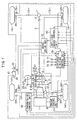
- numeral 1 denotes an engine arranged in the front of a vehicle.
- a driving force derived from the engine 1 is transmitted from an automatic transmission 2 disposed behind the engine 1 to a center differential 3 through a transmission output shaft 2a and a part of the driving force is transmitted from this center differential 3 to a rear final reduction gear unit 7 through a rear drive shaft 4, a propeller shaft 5 and a drive pinion shaft 6.
- the rest part of the driving force is transmitted to a front final reduction gear unit 11 through a transfer drive gear 8, a transfer driven gear 9 and a front drive shaft 10.
- the automatic transmission 2, the center differential 3, the front final reduction gear unit 11 and the like are integrally accommodated in a housing 12.
- the driving force inputted to the rear final reduction gear unit 7 is transmitted to a left rear wheel 14rl and a right rear wheel 14rr through a left rear drive shaft 13rl and a right rear drive shaft 13rr, respectively. Further, the driving force inputted to the front final reduction gear unit 11 is transmitted to a left front wheel 14fl and a right front wheel 14fr through a left front drive shaft 13fl and a right front drive shaft 13fr, respectively.
- the center differential 3 includes a first sun gear 15 having a relatively large diameter and connected to the transmission output shaft 2a and a first pinion 16 having a relatively small diameter and meshing with the first sun gear 15, and thus a first gear set is formed.
- the center differential 3 includes a second sun gear 17 having a relatively small diameter and connected to the rear drive shaft 4 and a second pinion 18 having a relatively large diameter and meshing with the second sun gear 17, and thus a second gear set is formed.
- first pinion 16 and the second pinion 18 are integrally formed with a pinion member 19 and a plurality of the pinion members (for example 3 pinion members) 19 are rotatably supported by a fixed shaft provided on a carrier 20.
- the carrier 20 is connected at the front end thereof with the transfer drive gear 8 so as to output the driving force to the front wheels.
- the transmission output shaft 2a is rotatably inserted into the carrier 20 from the front, while the rear drive shaft 4 is rotatably inserted thereinto from the rear.
- the first gear set composed of the first sun gear 15 and the first pinion 16
- the second gear set composed of the second sun gear 17 and the second pinion 18.
- the thus constituted center differential 3 receives the driving force from the transmission output shaft 2a and transmits it to the rear drive shaft 4 through the first sun gear 15, the first pinion 16, the second pinion 18 and the second sun gear 17. On the other hand, the driving force is transmitted to the transfer driven gear 9 through the carrier 20 and the transfer drive gear 8.
- the center differential 3 constitutes a compound type planetary gear without ring gear.
- the proper establishment of the intermeshing radii of those sun gears 15, 17 and pinions 16, 18 provides a reference torque distribution as required between the front and rear wheels. That is, it is possible to distribute a larger torque to the rear wheel than to the front, if desired.
- a hydraulically operated multiple disc clutch (hereinafter, referred to as a transfer clutch) 21 between the carrier 20 and the second sun gear 17 in order to perform driving force distribution by variably controlling the differential limiting force of the center differential 3 by means of a differential limiting control apparatus 70.
- the transfer clutch 21 comprises a plurality of driven plates 21a provided on the rear drive shaft 4 side and a plurality of drive plates 21b provided on the carrier 20 side, each of which is interleaved between two respective driven plates 21a. Further, the transfer clutch 21 is constituted so as to be operated by a hydraulic pressure supplied from a hydraulic power unit (not shown) which is electronically controlled by the differential limiting control apparatus 70.
- the transfer clutch 21 when the transfer clutch 21 is in a released condition, i.e., in a condition where the differential limiting force is zero, torque is distributed between the front and rear wheels according to a reference torque distribution ratio, for example 35:65 (35 % distributed to front wheels and 65 % distributed to rear wheels), of the center differential 3 itself.
- a reference torque distribution ratio for example 35:65 (35 % distributed to front wheels and 65 % distributed to rear wheels)
- the transfer clutch 21 when the transfer clutch 21 is fully engaged, the differentiation of the center differential 3 is restricted and torque is distributed at a specified torque distribution ratio, for example 50:50 (50 % distributed to front wheels and 50 % distributed to rear wheels), which is determined by the vehicle specification.
- the pressing force that is, the engagement torque of the transfer clutch 21 is controlled by the differential limiting control unit 70 so as to obtain any value of torque distribution ratio between the reference torque distribution ratio, for example, 35:65 and the specified torque distribution ratio, for example, 50:50.
- Numeral 25 denotes a brake drive section which is connected with a master cylinder 27 and the master cylinder 27 is connected with a brake pedal 26 which is operated by a vehicle driver.
- the master cylinder 27 When the driver operates the brake pedal 26, the master cylinder 27 generates a brake pressure and supplies it through the brake drive section 25 to a left front wheel cylinder 28fl for the left front wheel 14fl, a right front wheel cylinder 28fr for the right front wheel 14fr, a left rear wheel cylinder 28rl for the left rear wheel 14rl and a right rear wheel cylinder 28rr for the right rear wheel 14rr, respectively, thereby brake is applied to four wheels.
- the brake drive section 25 is a hydraulic unit including a hydraulic pressure source, a pressure reduction valve, a pressure intensifying valve and the like so as to supply the brake pressure independently to each wheel cylinder, 28fl, 28fr, 28rl and 28rr according to an input signal inputted thereto.
- Respective wheels 14fl, 14fr, 14rl and 14rr have wheel speed sensors (left front wheel speed sensor 29 fl , right front wheel speed sensor 29 fr , left rear wheel speed sensor 29 rl and right rear wheel speed sensor 29 rr ) for detecting a wheel speed.
- the master cylinder 27 includes a pressure sensor 30 for detecting a brake pressure and the steering wheel is equipped with a steering wheel rotation angle sensor 31 for detecting a rotation angle of the steering wheel.
- the brake pedal 26 has a brake pedal switch 32 for detecting an ON/OFF operation of the brake pedal 26 and an accelerator pedal 33 has an accelerator pedal switch 34 for detecting an ON/OFF operation of the accelerator pedal 33.
- the vehicle has an anti-lock brake control unit 40 which is constituted by a micro-computer and peripheral circuits.
- the anti-lock brake control unit 40 receives signals from the wheel speed sensors 29 fl , 29 fr , 29 rl and 29 rr and the brake pedal switch 32 and performs a judgment of the ABS operational condition (judgment whether the deceleration of the wheel has exceeded a specified value or not, when brake is applied), an operation of the anti-lock brake and the like.
- a wheel speed, an acceleration, a deceleration and a pseudo calculated vehicle speed of respective wheels are calculated based on signals from the wheel speed sensors 29 fl , 29 fr , 29 rl and 29 rr and also from the brake pedal switch 32.
- the pseudo calculated vehicle speed is a vehicle speed calculated by a specified deceleration using an initial wheel speed at the moment when it is judged that an emergency brake has been applied.
- an oil pressure mode is selected from three oil pressure modes, i.e., a pressure increasing mode, a pressure holding mode and a pressure decreasing mode, based on the result of comparison of the pseudo calculated vehicle speed with the wheel speed, the judgment of the magnitude of the acceleration and deceleration of respective wheels and the like.
- a brake control signal indicative of the selected oil pressure mode is outputted to the brake drive section 25. Also, this brake control signal is sent to a transmission control unit 50 and the differential limiting control unit 70.
- the transmission control unit 50 performs a shift control, a lock-up control and a line pressure control with respect to the automatic transmission 2. Further, according to the first embodiment, the transmission control unit 50 outputs a signal indicative of a gear ratio I m to the differential limiting control unit 70.
- the transmission control unit 50 receives an operation signal of the anti-lock brake control unit 40 when a deceleration of the wheel exceeds a predetermined value on braking and controls the transmission so as to shift up the gear position to a higher range in order to reduce the effect of engine brake.
- numeral 60 denotes an engine control unit in which miscellaneous controls such as a fuel injection control, an ignition timing control, an air-fuel ratio control, a boost control, a throttle angle control and the like, are performed with respect to the engine 1.
- the engine control unit 60 outputs a signal indicative of the throttle opening angle ⁇ th to the differential limiting control unit 70.
- the differential limiting control unit 70 receives signals indicative of wheel speeds from the respective wheel speed sensors 29 fl , 29 fr , 29 rl , 29 rr , a signal indicative of brake pressure from the pressure sensor 30 of the master cylinder 27, a signal indicative of the steering wheel rotation angle from the steering wheel rotation angle sensor 31, a signal indicative of the ON/OFF operation of the accelerator pedal 33 from the accelerator pedal switch 34, a signal indicative of the gear ratio I m from the transmission control unit 50, a signal indicative of the throttle opening angle ⁇ th from the engine control unit 60 and a signal indicative of the operation of the anti-lock brake from the anti-lock brake control unit 40.
- the differential limiting control unit 70 calculates a differential limiting force of the transfer clutch 21 based on these signals to make a torque distribution control on the differential 3 between 35:65 and 50:50 in terms of front-to-rear torque distribution ratio.
- the differential limiting force of the center differential 3 is established to be a predetermined differential limiting force S c and in case where the braking force is larger than the reference braking force F s , the differential limiting force of the center differential 3 is released, i.e., established to be zero.
- the predetermined differential limiting force S c is established as disclosed in Fig. 11 and on pages 26-29.
- the brake pressure in the master cylinder 27 increases according to the pedal effort.
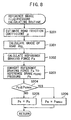
- the relationship between the braking force F b and the brake fluid pressure P b is given as shown in Fig. 4.
- the brake pedal 26 is depressed and the brake fluid pressure P b reaches P o , the braking force starts to rise.
- the brake pedal 26 is further depressed, if the brake fluid pressure P b is smaller than or equal to a reference brake fluid pressure P s (brake fluid pressure corresponding to the reference braking force F s ) , the differential limiting control is retained as it is.
- Fig. 5 is an explanatory diagram showing a value of the differential limiting force to be taken according to the brake fluid pressure.
- the differential limiting force of the center differential 3 is established to be a specified small value which is close to zero, so as to assist the restoration from wheel lock.
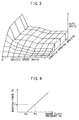
- the differential limiting force of the hydraulically operated transfer clutch 21 is determined as a duty ratio parameterizing a throttle opening angle ⁇ th and a vehicle speed V expressed on a three-dimensional map shown in Fig. 3.
- the differential limiting control comprises a normal control, a starting-up control, a steering control and a slip control.
- one map per each gear speed is prepared.
- five maps including a reverse speed are prepared.
- the differential limiting torque is controlled so as to become lower as the throttle opening angle ⁇ th is small and the vehicle speed V is large, thereby the turning performance and fuel economy are improved.
- the differential limiting torque is controlled so as to be proportional to the throttle opening angle ⁇ th in order to secure a smooth and easy starting on a road surface having low friction coefficient.
- the differential limiting torque is controlled so as to be reduced compared to the normal control according to a rear-to-front rotation ratio NR/NF (NR: rotation number of the rear wheel, NF: rotation number of the front wheel) in order to enhance the steering feeling at a specified low speed area of the vehicle.
- NR/NF rotation number of the rear wheel
- NF rotation number of the front wheel
- the differential limiting torque is controlled so as to increase in order to secure the maximum driving force or to improve a running stability.
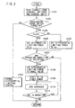
- the control process in the differential limiting control unit 70 will be described with reference to a flowchart shown in Fig. 2.
- the control program is executed every specified time during running of the vehicle.
- ⁇ s ⁇ a step (hereinafter referred to as ⁇ s ⁇ ) 101, signals are read from miscellaneous sensors, switches and control units and the program goes to S102 where the state of the accelerator pedal switch 34 is judged.
- the program skips to S103 where the center differential 3 is set to the aforesaid normal control and the program leaves the routine.
- the program goes to S104 where the break fluid pressure P b is compared with the reference brake fluid pressure P s corresponding to the predetermined reference braking force F s .
- the program goes from S105 or S106 to S107.
- S107 it is judged whether or not the ABS operational condition (the deceleration of the wheel exceeds a specified value on braking) is satisfied. If it is not satisfied, the program leaves the routine and if it is satisfied, the program goes to S108 where the differential limiting force of the center differential 3 is established to be a specified small value close to zero so as to assist the restoration from the wheel lock. At this time, even if the differential limiting force is set to zero, it returns again to that small value.
- the program goes to S111 where it is judged whether or not the ABS is being operated. If the ABS is being operated, the program returns to S110 to continue the operation of the ABS and if the ABS is not being operated, the program leaves the routine.
- the differential limiting force of the center differential 3 is set to the predetermined differential limiting force S c .
- the differential limiting force is set to an appropriate value, when the accelerator is released on a slippery road such as a snowy road, the vehicle can be prevented from falling into an excessive under steer characteristic or an excessive over steer characteristic.
- the power train in case where the braking force on braking exceeds the reference braking force F s , i.e., in case where the ABS control is surely needed, since the differential limiting force is released to zero in order to detect the slip state of respective wheels independently, the power train can be prevented from causing a shock when the connection between front and rear wheels is released, even in case where an emergency brake is applied on a road surface with high friction coefficient.
- Figs. 6 and 7 show a second embodiment of the present invention.
- the feature of the second embodiment is to determine the reference brake fluid pressure P s according to a road friction coefficient and other constructions and operations are identical to those of the first embodiment.
- the road friction coefficient referred in the second embodiment is, for example, a road fiction coefficient calculated in the road friction coefficient estimation method proposed by the inventor of the present invention in Japanese Patent Application Laid-open No. Toku-Kai-Hei 8-2274.
- the cornering power of the front and rear wheels is estimated being extended to the non-linear region based on the equation of motion about the lateral motion of the vehicle and a road friction coefficient is estimated by taking the ratio of thus estimated cornering power to the equivalent cornering power of the front and rear wheels on a road surface having a high friction coefficient.
- the differential limiting control unit 70 according to the second embodiment of the present invention is additionally connected with a yaw rate sensor 71 as shown in Fig. 1.
- a yaw rate sensor 71 as shown in Fig. 1.
- the program goes to S200 where the reference brake fluid pressure P s is calculated according to a reference brake fluid pressure calculating routine which will be described hereinafter and then steps to S104 where the brake fluid pressure P b is compared with the reference brake fluid pressure P s calculated at S200.
- the processes after S104 are the same as those in the first embodiment.
- the program goes to S204 wherein the calculated reference brake fluid pressure P s is compared with an upper limit value P smax .
- the upper limit value P smax is established to be a level at which the shock in the drive train is endurable when an actual vehicle is tested.
- the value is, for example, established to be a brake fluid pressure corresponding to a braking force which generates a deceleration of 0.5 G (gravitational acceleration) or so.
- the program goes to S205 in which the reference brake fluid pressure P s is established to the calculated reference brake fluid pressure P s . If the calculated reference brake fluid pressure P s is equal to or larger than the upper limit value P smax , the program goes to S206 in which the reference brake fluid pressure P s is established to the upper limit value P smax and the program leaves the routine.
- the reference brake fluid pressure is established according to the road friction coefficient, an accurate reference brake fluid pressure can be established according to the road situation and also the timing immediately before generating a wheel-locking can be obtained with accuracy.
- the drive train shock caused when the transference of the differential limiting force suddenly disappears during running especially on a road surface with high friction coefficient such as a road surface of a dry pavement, can be avoided.
- Fig 8 is a flowchart of a reference brake fluid pressure calculating routine according to a third embodiment of the present invention.
- the feature of the third embodiment is to calculate the reference brake fluid pressure P s also taking the effect of the grade of the road into consideration and other constructions and operations are identical to those of the second embodiment.
- ⁇ SL (longitudinal acceleration - rate of change of vehicle velocity/g) / 100 where ⁇ SL is grade of road (plus sign indicates up-grade) and g is gravitational acceleration.
- the grade of the road may be calculated from altitude data obtained from a navigation system.
- the differential limiting control unit 70 according to the third embodiment of the present invention is additionally to the second embodiment connected with a longitudinal acceleration sensor 72 as shown in Fig. 1.
- a longitudinal acceleration sensor 72 as shown in Fig. 1.
- the reference brake fluid pressure is established in accordance with the road friction coefficient ⁇ and the grade ⁇ SL of the road, an accurate reference brake fluid pressure can be established taking the road condition and the up and down road configuration into consideration and as a result the timing immediately before the wheel lock can be accurately obtained.
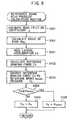
- Fig 9 is a flowchart of a reference brake fluid pressure calculating routine according to a fourth embodiment of the present invention.
- the feature of the fourth embodiment is to calculate the reference brake fluid pressure taking the effect of lateral acceleration generated when turning into consideration and other constructions and operations are identical to those of the third embodiment.
- the differential limiting control unit 70 according to the fourth embodiment of the present invention is additionally to the third embodiment connected with a lateral acceleration sensor 73 as shown in Fig. 1.
- the lateral acceleration G y may be derived from the following formula using a steering wheel rotation angle ⁇ f , a steering gear ratio N, a vehicle stability factor A and a wheel base L.
- G y ⁇ f /N ⁇ V 2 /(1 + A ⁇ V 2 ) ⁇ L/g
- the program goes to S402 where the reference braking force F s is calculated according to the following formula using the road friction coefficient ⁇ , the grade ⁇ SL of the road and the lateral acceleration G y :
- F s a 3 ⁇ cos ( ⁇ SL ) ⁇ W ⁇ ( ⁇ 2 - G y 2 ) 1 ⁇ 2 + b 3
- W is vehicle weight
- a 3 , b 3 are correction coefficients predetermined taking errors on detecting the road friction coefficient ⁇ , the grade ⁇ SL of the road ) and the lateral acceleration G y into consideration.
- the reference brake fluid pressure is determined based on the road friction coefficient ⁇ , the grade ⁇ SL of the road and the lateral acceleration. G y , an accurate reference brake fluid pressure can be established in accordance with the road condition, the up and down road configuration and the turning condition of the vehicle and as a result the timing immediately before the wheel lock can be accurately obtained.
- Figs. 10 through 12 show a fifth embodiment of the present invention.
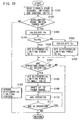
- Fig. 10 is a flowchart showing the differential limiting control and
- Fig. 11 is a flowchart of the differential limiting force calculating routine.
- Fig. 12 is an explanatory view showing the relationship between engine speed and engine brake torque.
- the feature of the fifth embodiment is to establish the reference brake fluid pressure such that the engine braking force is distributed between the front and rear wheels at a distribution ratio corresponding to the front-to-rear weight distribution ratio and other constructions and operations are identical to those of the fourth embodiment.
- the program goes to S105 where the differential limiting force of the center differential 3 is established to be the S c which has been calculated at S500 and goes to S107.
- the processes after S107 are the same as those in the fourth embodiment.
- an engine speed N e is read from the engine control unit 60 and at S502 an engine brake torque T e on the turbine shaft is read based on the engine speed N e from a map on which the relationship between the engine speed N e and the corresponding engine brake torque T e is shown in Fig. 12.
- the front-to-rear weight distribution ratio is 6:4 and a larger engine braking force is exerted to the rear wheel compared to the front wheel, the slip ratio of the rear wheel is larger than that of the front wheel. Therefore, the rotation of the rear wheel becomes smaller than that of the front wheel. In this state, when the differential limiting force is applied, a part of the braking force flows from the rear wheel side to the front wheel side.
- the differential limiting force should be established so that the differential limiting force S c secures 0.2 ⁇ B e at a minimum. That is, the differential limiting force S c should be 0.2 ⁇ B e .
- the engine braking force is correctly distributed between the front and rear wheels at a distribution ratio corresponding to the front-to-rear weight distribution ratio, it is possible to reduce the rotational difference between front and rear wheels so as not to cause a slip only on the front or rear wheel, thereby a stable under-steer characteristic can be maintained.
- Figs. 13 through 15 show a sixth embodiment of the present invention.
- Fig. 13 is a flowchart of the differential limiting control and
- Fig. 14 is a flowchart of the differential limiting force calculating routine.
- Fig. 15 is an explanatory view showing areas of the differential limiting force in relation to wheel rotational deceleration and brake fluid pressure.
- the feature of the sixth embodiment is to correct the differential limiting force so as to release the differential limiting if the wheel rotational deceleration is larger than a predetermined reference wheel rotational deceleration and other constructions and operations are identical to those of the fifth embodiment.
- the program goes to S600 where the differential limiting force is subjected to the process by the differential limiting force calculating routine which will be described hereinafter. That is, the differential limiting force S c calculated at S500 is corrected to another value depending on the wheel rotational deceleration at S600.
- the differential limiting force is corrected to a lower value than that already calculated in order to detect the slip state more easily and also in order to prevent the front or rear wheels from causing a slip abruptly.
- the differential limiting force is selected, as shown in Fig. 15, from respective areas in a map parameterizing the wheel rotational deceleration (- ⁇ V w )and the brake fluid pressure P b .
- the anti-lock brake control unit since the differential limiting force is corrected in the direction of releasing the differential limiting if the wheel rotational deceleration is larger than the reference wheel rotational deceleration, the anti-lock brake control unit is surely operated under the condition that the wheel-locking is imminent even when the brake pedal is lightly depressed.
- Figs. 16 through 18 show a seventh embodiment of the present invention.
- Fig. 16 is a flowchart of the differential limiting force calculating routine and
- Fig. 17 is an explanatory view of areas of the differential limiting force in relation to the wheel rotational deceleration (- ⁇ V w )and the brake fluid pressure P b .
- Fig. 18 is a graph showing a relationship between the road friction coefficient ⁇ and the reference wheel rotational deceleration A.
- the feature of the seventh embodiment is to vary the reference wheel rotational deceleration according to the brake fluid pressure and other constructions and operations are identical to those of the sixth embodiment.
- a wheel rotational deceleration (- ⁇ V w ) is calculated from wheel speed and then at S700 a reference wheel deceleration A w is established.
- the reference wheel deceleration A w is not a fixed value like in the sixth embodiment.
- the reference wheel deceleration A w is established to be a low value when the brake fluid pressure P b is low and established to be a high value when P b is high, as illustrated in Fig. 17. Therefore, the differential limiting force can take a small value like S d even when the brake fluid pressure P b is low and also the wheel rotational deceleration(- ⁇ V w ) is small. For example, when the vehicle travels on a road surface with low friction coefficient, the wheel lock easily occurs even with a light depression of the brake pedal. Under such conditions, according to this embodiment, since the differential limiting force is established to be a low value, the ABS operates effectively.
- Fig. 18 shows a case where the reference wheel rotational deceleration A w established at S700 is determined according to the road friction coefficient ⁇ .
- the vehicle tends to cause a wheel lock when a light brake is applied on a road surface having low friction coefficient.
- the ABS operates under such conditions by establishing the reference wheel rotational deceleration to be a small value when the road friction coefficient is low.
- the state of the wheel lock can be detected more accurately.
- the vehicle has an excess under-steer or over-steer characteristic due to engine brake exerted only to front or rear wheels when it travels on a slippery road surface like snowy road with accelerator off. Under this condition, to prevent this, the differential limiting between front and rear wheels is released to detect the slip condition on respective wheels independently and to operate the ABS effectively. Further, when an emergency brake is applied on a road surface with high friction coefficient, the drive train of the vehicle can be prevented from causing a shock due to an sudden release of the engagement between front and rear wheels.
Landscapes
- Engineering & Computer Science (AREA)
- Transportation (AREA)
- Mechanical Engineering (AREA)
- Chemical & Material Sciences (AREA)
- Combustion & Propulsion (AREA)
- Automation & Control Theory (AREA)
- Arrangement And Driving Of Transmission Devices (AREA)
- Regulating Braking Force (AREA)
- Retarders (AREA)
Claims (10)
- Differentialsperren-Steuervorrichtung eines vierradgetriebenen Fahrzeugs mit einem Motor, Rädern, einem Gaspedal (33) zum Steuern des Motors, einem Bremspedal (26) zum Ausüben einer Bremskraft auf die Räder und einer Antiblockier-Bremssteuervorrichtung (40) zum Steuern der Bremskraft, die auf die jeweiligen Räder auszuüben ist, um so die Räder daran zu hindern, blockiert zu werden, einem Zentraldifferential, einer hydraulisch betätigten Mehrscheibenkupplung (21) zum Ausüben einer Differentialsperrkraft auf das Zentraldifferential und einer Differentialsperren-Steuereinheit zum Einstellen eines Sollwerts der Differentialsperrkraft und zum hydraulischen Steuern der Mehrscheibenkupplung, um so den Sollwert der Differentialsperrkraft im Zentraldifferential zu erzeugen, dadurch gekennzeichnet, daß sie aufweist:eine Differentialsperrkraft-Berechnungseinrichtung zum Berechnen eines vorbestimmten Werts (Sc) der Differentialsperrkraft als Sollwert, so daß eine Motorbremskraft (Be) zwischen den Vorder- und Hinterrädern mit einem Verteilungsverhältnis in Entsprechung zu einem Gewichtsverteilungsverhältnis zwischen den Vorder- und Hinterrädern verteilt wird, wenn das Bremspedal bei losgelassenem Gaspedal nicht betätigt oder wenn das Bremspedal bei losgelassenem Gaspedal betätigt wird und wenn die Bremskraft kleiner als eine Referenz-Bremskraft (Fs) ist;eine Differentialsperrkraft-Einstelleinrichtung zum Einstellen des vorbestimmten Werts als Differentialsperrkraft (Sc) des Zentraldifferentials, nachdem der vorbestimmte Wert berechnet ist, um so die Motorbremskraft zwischen den Vorder- und Hinterrädern mit dem Verteilungsverhältnis in Entsprechung zum Gewichtsverteilungsverhältnis zwischen den Vorder- und Hinterrädern zu verteilen; undeine Differentialsperrkraft-Löseeinrichtung zum Lösen der Differentialsperrkraft des Zentraldifferentials, wenn die Bremskraft größer als die vorbestimmte Referenz-Bremskraft ist.
- Vorrichtung nach Anspruch 1 mit:einer Differentialsperrkraft-Einstelleinrichtung zum Einstellen des vorbestimmten Werts als Differentialsperrkraft des Zentraldifferentials, nachdem der vorbestimmte Wert berechnet ist, wenn eine Raddrehverzögerung (-ΔVw) kleiner als eine vorbestimmte Referenz-Raddrehverzögerung (Aw) ist, um so die Motorbremskraft zwischen den Vorder- und Hinterrädern mit dem Verteilungsverhältnis in Entsprechung zum Gewichtsverteilungsverhältnis zwischen den Vorder- und Hinterrädern zu verteilen, und zum Korrigieren einer in der Differentialsperrkraft-Berechnungseinrichtung des Zentraldifferentials berechneten Differentialsperrkraft auf einen Wert (Sd), der kleiner als der vorbestimmte Wert ist, nachdem der vorbestimmte Wert berechnet ist, wenn eine Raddrehverzögerung größer als die vorbestimmte Referenz-Raddrehverzögerung ist, um so die Differentialsperrkraft des Zentraldifferentials zu lösen, auch wenn die Bremskraft klein ist.
- Vorrichtung nach Anspruch 1 oder 2, ferner mit:einer Differentialsperrkraft-Korrektureinrichtung zum Korrigieren der in der Differentialsperrkraft-Einstelleinrichtung eingestellten Differentialsperrkraft auf einen ersten Wert nahe null, wenn die Antiblockier-Bremssteuervorrichtung zu arbeiten beginnt.
- Vorrichtung nach Anspruch 1, 2 oder 3, wobei
der festgelegte Wert (Sd) ein Festwert ist. - Vorrichtung nach einem der Ansprüche 1 bis 4, wobei
die Referenz-Bremskraft eine Bremskraft unmittelbar vor Blockieren der Räder ist. - Vorrichtung nach einem der Ansprüche 1 bis 5, wobei
die Referenz-Bremskraft mindestens entsprechend einem Fahrbahn-Reibungskoeffizient (µ) einer Fahrbahn eingestellt wird, auf der das Fahrzeug fährt. - Vorrichtung nach einem der Ansprüche 1 bis 6, wobei
die Referenz-Bremskraft mindestens entsprechend einer Steigung (SL) einer Fahrbahn eingestellt wird, auf der das Fahrzeug fährt. - Vorrichtung nach einem der Ansprüche 1 bis 7, wobei
die Referenz-Bremskraft mindestens entsprechend einer Querbeschleunigung (Gy) eingestellt wird, die auf das Fahrzeug beim Abbiegen ausgeübt wird. - Vorrichtung nach einem der Ansprüche 2 bis 8, wobei
die Referenz-Raddrehverzögerung (Aw) auf einen kleineren Wert eingestellt wird, wenn die Bremskraft (Fb) klein wird. - Vorrichtung nach einem der Ansprüche 2 bis 9, wobei
die Referenz-Raddrehverzögerung entsprechend einem Fahrbahn-Reibungskoeffizient (µ) einer Fahrbahn eingestellt wird, auf der das Fahrzeug fährt.
Priority Applications (1)
| Application Number | Priority Date | Filing Date | Title |
|---|---|---|---|
| EP04024279A EP1495902B1 (de) | 1997-10-24 | 1998-10-23 | Differentialsperrensteuerung für ein vierradangetriebenes Fahrzeug |
Applications Claiming Priority (3)
| Application Number | Priority Date | Filing Date | Title |
|---|---|---|---|
| JP29269397 | 1997-10-24 | ||
| JP29269397A JP4014016B2 (ja) | 1997-10-24 | 1997-10-24 | 4輪駆動車の差動制限制御装置 |
| JP292693/97 | 1997-10-24 |
Related Child Applications (1)
| Application Number | Title | Priority Date | Filing Date |
|---|---|---|---|
| EP04024279A Division EP1495902B1 (de) | 1997-10-24 | 1998-10-23 | Differentialsperrensteuerung für ein vierradangetriebenes Fahrzeug |
Publications (3)
| Publication Number | Publication Date |
|---|---|
| EP0911205A2 EP0911205A2 (de) | 1999-04-28 |
| EP0911205A3 EP0911205A3 (de) | 2001-11-07 |
| EP0911205B1 true EP0911205B1 (de) | 2005-03-23 |
Family
ID=17785087
Family Applications (2)
| Application Number | Title | Priority Date | Filing Date |
|---|---|---|---|
| EP04024279A Expired - Lifetime EP1495902B1 (de) | 1997-10-24 | 1998-10-23 | Differentialsperrensteuerung für ein vierradangetriebenes Fahrzeug |
| EP98119783A Expired - Lifetime EP0911205B1 (de) | 1997-10-24 | 1998-10-23 | Steuerungssystem für die Grenzkraft eines Differentials in einem vierradangetriebenen Fahrzeug |
Family Applications Before (1)
| Application Number | Title | Priority Date | Filing Date |
|---|---|---|---|
| EP04024279A Expired - Lifetime EP1495902B1 (de) | 1997-10-24 | 1998-10-23 | Differentialsperrensteuerung für ein vierradangetriebenes Fahrzeug |
Country Status (4)
| Country | Link |
|---|---|
| US (1) | US6189643B1 (de) |
| EP (2) | EP1495902B1 (de) |
| JP (1) | JP4014016B2 (de) |
| DE (2) | DE69829449T2 (de) |
Families Citing this family (61)
| Publication number | Priority date | Publication date | Assignee | Title |
|---|---|---|---|---|
| US7275607B2 (en) | 1999-06-04 | 2007-10-02 | Deka Products Limited Partnership | Control of a personal transporter based on user position |
| JP2000344077A (ja) | 1999-06-08 | 2000-12-12 | Toyota Motor Corp | 車両の挙動制御装置 |
| JP2001048000A (ja) * | 1999-08-10 | 2001-02-20 | Nisshinbo Ind Inc | アンチロックブレーキ制御装置 |
| DE19950205C1 (de) * | 1999-10-19 | 2000-11-02 | Bayerische Motoren Werke Ag | Steuersystem zur variablen Drehmomentverteilung für ein vierradgetriebenes Fahrzeug |
| JP3960740B2 (ja) | 2000-07-31 | 2007-08-15 | トヨタ自動車株式会社 | 車両の制動制御装置 |
| JP4529255B2 (ja) * | 2000-08-25 | 2010-08-25 | 株式会社アドヴィックス | 車両用制動制御装置 |
| JP2002087095A (ja) * | 2000-09-12 | 2002-03-26 | Komatsu Ltd | 車両のタイヤロック防止装置 |
| JP4209075B2 (ja) * | 2000-09-14 | 2009-01-14 | 三菱自動車工業株式会社 | 車両用差動制限装置 |
| DE10054023A1 (de) * | 2000-11-01 | 2002-05-08 | Bayerische Motoren Werke Ag | Steuersytem zur variablen Drehmomentverteilung |
| JP3589202B2 (ja) * | 2001-07-13 | 2004-11-17 | 日産自動車株式会社 | 4輪駆動車両の駆動力制御装置 |
| US6591179B1 (en) | 2002-01-04 | 2003-07-08 | Delphi Technologies, Inc. | Method and system for progressive engagement of all-wheel drive |
| DE10208239A1 (de) * | 2002-02-26 | 2003-09-04 | Zahnradfabrik Friedrichshafen | Vorrichtung zur selbsttätigen Ansteuerung einer Differentialsperre |
| AT6086U1 (de) * | 2002-04-12 | 2003-04-25 | Steyr Powertrain Ag & Co Kg | Kraftfahrzeug mit einem bremssystem und einem antriebssystem |
| DE10216565A1 (de) * | 2002-04-15 | 2003-10-23 | Zahnradfabrik Friedrichshafen | Vorrichtung und Verfahren zur selbsttätigen Ansteuerung von mindestens einer Differentialsperre |
| JP4137503B2 (ja) * | 2002-04-26 | 2008-08-20 | 株式会社ジェイテクト | 4輪駆動車の駆動力配分制御装置 |
| WO2004007264A1 (en) | 2002-07-12 | 2004-01-22 | Deka Products Limited Partnership | Control of a transporter based on attitude |
| DE10346113B4 (de) * | 2002-10-15 | 2012-08-09 | Volkswagen Ag | Verfahren und Vorrichtung zur Antriebssteuerung eines Kraftfahrzeuges |
| DE10304813A1 (de) * | 2003-02-06 | 2004-08-19 | Audi Ag | Antriebsvorrichtung |
| DE10312879A1 (de) * | 2003-03-22 | 2004-10-07 | Bayerische Motoren Werke Ag | Steuersystem zur variablen Drehmomentverteilung |
| US7463964B2 (en) | 2003-09-09 | 2008-12-09 | Mitsubishi Jidosha Kogyo K.K. | Driving force distribution and controlling apparatus for vehicle and driving force distribution and controlling method for vehicle |
| US20050116537A1 (en) * | 2003-12-01 | 2005-06-02 | Zalewski John D. | Combination braking and traction control system for a motor vehicle |
| GB2414217B (en) * | 2004-05-21 | 2007-08-01 | Ford Global Tech Llc | Vehicle differential control |
| JP4476742B2 (ja) * | 2004-08-19 | 2010-06-09 | 本田技研工業株式会社 | 4輪駆動車両の制御方法 |
| DE602005003617T2 (de) * | 2004-08-19 | 2008-04-10 | Honda Motor Co., Ltd. | Verfahren zur Kontrolle eines Allradfahrzeugs |
| JP4417203B2 (ja) | 2004-08-23 | 2010-02-17 | 本田技研工業株式会社 | 4輪駆動車両の駆動力制御方法 |
| ES2362238T3 (es) * | 2006-02-03 | 2011-06-30 | Eaton Corporation | Control de tracción y desviación lateral con estabilidad mejorada, utilizando un diferencial controlado eletrónicamente con deslizamiento limitado. |
| JP2007210418A (ja) * | 2006-02-08 | 2007-08-23 | Toyota Motor Corp | 車両の制御装置 |
| JP4844720B2 (ja) | 2006-03-07 | 2011-12-28 | 三菱自動車工業株式会社 | 車両の差動制限制御装置 |
| US20090271087A1 (en) * | 2006-11-29 | 2009-10-29 | Yutaka Motonaga | Control device and engine control device |
| US7832518B2 (en) * | 2007-03-22 | 2010-11-16 | Ford Global Technologies, Llc | Torque distribution control in a motor vehicle |
| FR2918945B1 (fr) * | 2007-07-19 | 2009-10-09 | Messier Bugatti Sa | Procede de commande d'un frein de vehicule avec correction en couple |
| JP4757333B2 (ja) * | 2009-08-05 | 2011-08-24 | 本田技研工業株式会社 | 車両の駆動力制御装置 |
| US20110269595A1 (en) | 2010-04-30 | 2011-11-03 | American Axle & Manufacturing Inc. | Control strategy for operating a locking differential |
| DE102011003298A1 (de) * | 2011-01-28 | 2012-07-12 | Audi Ag | Verfahren zur Erkennung und Korrektur der Fahrzeugreferenzgeschwindigkeit und Fahrzeugsystem |
| US8312956B2 (en) * | 2011-02-15 | 2012-11-20 | Deere & Company | Auto inter-axle differential lock engagement for improved braking capacity |
| JP5663368B2 (ja) * | 2011-03-30 | 2015-02-04 | 富士重工業株式会社 | 車両の運転支援制御装置 |
| SE536389C2 (sv) * | 2011-05-23 | 2013-10-01 | Bae Systems Haegglunds Ab | Förfarande och system för att styra en differentialkonfiguration |
| DE102012006176B4 (de) * | 2012-03-27 | 2024-11-07 | Zf Cv Systems Hannover Gmbh | Steuern mehrerer angetriebener Achsen eines Kraftfahrzeugs |
| US8825314B2 (en) * | 2012-07-31 | 2014-09-02 | Caterpillar Inc. | Work machine drive train torque vectoring |
| US8918263B2 (en) | 2013-03-14 | 2014-12-23 | Clark Equipment Company | Traction control for power machine |
| GB2514161B (en) * | 2013-05-16 | 2015-09-02 | Jaguar Land Rover Ltd | Vehicle control system and method |
| US9758038B2 (en) | 2014-02-27 | 2017-09-12 | Nissan Motor Co., Ltd. | Clutch control device for four-wheel drive vehicle |
| CN104760594B (zh) * | 2015-02-28 | 2017-01-25 | 吉林大学 | 瞬时能耗最小的车轮转矩分配方法 |
| CA3015608A1 (en) | 2016-02-23 | 2017-08-31 | Deka Products Limited Partnership | Mobility device control system |
| US10926756B2 (en) | 2016-02-23 | 2021-02-23 | Deka Products Limited Partnership | Mobility device |
| US9809207B2 (en) | 2016-02-23 | 2017-11-07 | Honda Motor Co., Ltd. | Vehicle control system |
| US9821778B2 (en) | 2016-02-23 | 2017-11-21 | Honda Motor Co., Ltd. | Vehicle control system |
| US10802495B2 (en) | 2016-04-14 | 2020-10-13 | Deka Products Limited Partnership | User control device for a transporter |
| US11399995B2 (en) | 2016-02-23 | 2022-08-02 | Deka Products Limited Partnership | Mobility device |
| US10908045B2 (en) | 2016-02-23 | 2021-02-02 | Deka Products Limited Partnership | Mobility device |
| CN105857304B (zh) * | 2016-05-23 | 2018-11-23 | 武汉理工大学 | 基于四轮驱动汽车力矩分配控制系统 |
| CN106183892B (zh) * | 2016-10-09 | 2018-08-10 | 重庆理工大学 | 电动轮驱动汽车的试验样车及驱动稳定性控制方法 |
| JP6520890B2 (ja) | 2016-11-02 | 2019-05-29 | トヨタ自動車株式会社 | 四輪駆動車の挙動制御装置 |
| JP6729441B2 (ja) * | 2017-02-20 | 2020-07-22 | トヨタ自動車株式会社 | 四輪駆動車両の制御装置 |
| JP6652093B2 (ja) * | 2017-03-15 | 2020-02-19 | トヨタ自動車株式会社 | 四輪駆動車両の制御装置 |
| JP2018167703A (ja) * | 2017-03-30 | 2018-11-01 | トヨタ自動車株式会社 | 四輪駆動車両の制御装置 |
| USD846452S1 (en) | 2017-05-20 | 2019-04-23 | Deka Products Limited Partnership | Display housing |
| USD1047785S1 (en) | 2017-05-20 | 2024-10-22 | Deka Products Limited Partnership | Toggle control device |
| USD829612S1 (en) | 2017-05-20 | 2018-10-02 | Deka Products Limited Partnership | Set of toggles |
| US11681293B2 (en) | 2018-06-07 | 2023-06-20 | Deka Products Limited Partnership | System and method for distributed utility service execution |
| DE102024202346A1 (de) * | 2024-03-13 | 2025-10-02 | Robert Bosch Gesellschaft mit beschränkter Haftung | Verfahren zum Anpassen der Drehzahlen der Fahrzeugräder wenigstens einer Fahrzeugachse eines Fahrzeugs und ein Fahrzeug |
Family Cites Families (11)
| Publication number | Priority date | Publication date | Assignee | Title |
|---|---|---|---|---|
| US4770266A (en) * | 1985-08-13 | 1988-09-13 | Mazda Motor Corporation | Brake control system for four-wheel drive vehicle |
| JPS6243355A (ja) | 1985-08-13 | 1987-02-25 | Mazda Motor Corp | 4輪駆動車のブレ−キ制御装置 |
| DE3638665A1 (de) * | 1986-11-12 | 1988-05-19 | Bosch Gmbh Robert | Antiblockierregelsystem |
| JPS6443355A (en) | 1987-08-10 | 1989-02-15 | Sumitomo Heavy Industries | Wet specific gravity screener |
| JP2638990B2 (ja) * | 1988-08-31 | 1997-08-06 | 日産自動車株式会社 | 四輪駆動車の駆動力配分制御装置 |
| DE4037654A1 (de) * | 1990-11-27 | 1992-06-04 | Wabco Westinghouse Fahrzeug | Antiblockiersystem fuer allradgetriebene fahrzeuge |
| US5289895A (en) * | 1991-06-27 | 1994-03-01 | Mazda Motor Corporation | Control system for vehicle with differential restricting device |
| JPH0688504A (ja) | 1992-09-07 | 1994-03-29 | Toshiba Corp | タービン高速バルブ制御装置 |
| JP3268124B2 (ja) | 1994-06-27 | 2002-03-25 | 富士重工業株式会社 | 車両のトルク配分制御装置 |
| JP3617680B2 (ja) * | 1995-01-31 | 2005-02-09 | 富士重工業株式会社 | 4輪駆動車のトラクション制御装置 |
| US6001041A (en) * | 1996-07-05 | 1999-12-14 | Mitsubishi Jidosha Kogyo Kabushiki Kaisha | Power transmission |
-
1997
- 1997-10-24 JP JP29269397A patent/JP4014016B2/ja not_active Expired - Fee Related
-
1998
- 1998-10-19 US US09/174,553 patent/US6189643B1/en not_active Expired - Lifetime
- 1998-10-23 DE DE69829449T patent/DE69829449T2/de not_active Expired - Lifetime
- 1998-10-23 EP EP04024279A patent/EP1495902B1/de not_active Expired - Lifetime
- 1998-10-23 DE DE69841833T patent/DE69841833D1/de not_active Expired - Lifetime
- 1998-10-23 EP EP98119783A patent/EP0911205B1/de not_active Expired - Lifetime
Also Published As
| Publication number | Publication date |
|---|---|
| EP1495902A2 (de) | 2005-01-12 |
| EP0911205A3 (de) | 2001-11-07 |
| JPH11123946A (ja) | 1999-05-11 |
| DE69829449D1 (de) | 2005-04-28 |
| DE69841833D1 (de) | 2010-09-23 |
| JP4014016B2 (ja) | 2007-11-28 |
| EP1495902B1 (de) | 2010-08-11 |
| EP0911205A2 (de) | 1999-04-28 |
| DE69829449T2 (de) | 2005-09-01 |
| US6189643B1 (en) | 2001-02-20 |
| EP1495902A3 (de) | 2005-03-23 |
Similar Documents
| Publication | Publication Date | Title |
|---|---|---|
| EP1495902B1 (de) | Differentialsperrensteuerung für ein vierradangetriebenes Fahrzeug | |
| US6094614A (en) | Driving force distribution control system and road friction coefficient estimating apparatus | |
| EP0963892B1 (de) | Drehmomentverteilungsregelsystem für ein allradgetriebenes Fahrzeug | |
| JP4396002B2 (ja) | 車輌のトラクション制御装置 | |
| US6059064A (en) | Hybrid vehicle | |
| US7458650B2 (en) | Regenerative braking system for motor vehicles | |
| US5168955A (en) | Traction control system for four-wheel drive vehicle | |
| JP4058932B2 (ja) | 車輌用制動制御装置 | |
| US7493982B2 (en) | Control device for a four-wheel drive vehicle | |
| JP3563869B2 (ja) | エンジン出力制御装置 | |
| US6064930A (en) | Yaw moment control system in vehicle | |
| EP1203688A2 (de) | Antriebskraftverteilungssystem eines Fahrzeugs | |
| EP1400390A2 (de) | Antriebskraftverteilungs- Steuerungsgerät für ein vierradgetriebenes Fahrzeug | |
| JP2001287561A (ja) | 四輪駆動車両の駆動力制御装置 | |
| EP1431149B1 (de) | Bremskraftregler und Bremskraftregelungsverfahren für Kraftfahrzeuge | |
| CN108621787B (zh) | 四轮驱动车辆的控制装置 | |
| JP4215861B2 (ja) | 4輪駆動車の動力配分制御装置 | |
| US6189642B1 (en) | Vehicle drive torque distribution control system | |
| EP1522474B1 (de) | Vorrichtung zur Regelung der Fahrzeugbewegung | |
| JP3781101B2 (ja) | 車輌の制動力制御装置 | |
| JP2004231004A (ja) | 車輌用車輪状態推定装置 | |
| JPH04135958A (ja) | 車両のアンチスキッドブレーキ装置 | |
| JP4701941B2 (ja) | 車輌の車体速度推定装置 | |
| JPH11278088A (ja) | 車両用トルク配分クラッチの制御装置および車両用パーキングブレーキターン判定装置 | |
| JP3518464B2 (ja) | 四輪駆動車の駆動力配分制御装置 |
Legal Events
| Date | Code | Title | Description |
|---|---|---|---|
| PUAI | Public reference made under article 153(3) epc to a published international application that has entered the european phase |
Free format text: ORIGINAL CODE: 0009012 |
|
| AK | Designated contracting states |
Kind code of ref document: A2 Designated state(s): AT BE CH CY DE DK ES FI FR GB GR IE IT LI LU MC NL PT SE Kind code of ref document: A2 Designated state(s): DE GB |
|
| AX | Request for extension of the european patent |
Free format text: AL;LT;LV;MK;RO;SI |
|
| PUAL | Search report despatched |
Free format text: ORIGINAL CODE: 0009013 |
|
| AK | Designated contracting states |
Kind code of ref document: A3 Designated state(s): AT BE CH CY DE DK ES FI FR GB GR IE IT LI LU MC NL PT SE |
|
| AX | Request for extension of the european patent |
Free format text: AL;LT;LV;MK;RO;SI |
|
| 17P | Request for examination filed |
Effective date: 20011121 |
|
| AKX | Designation fees paid |
Free format text: DE GB |
|
| 17Q | First examination report despatched |
Effective date: 20030220 |
|
| GRAP | Despatch of communication of intention to grant a patent |
Free format text: ORIGINAL CODE: EPIDOSNIGR1 |
|
| GRAS | Grant fee paid |
Free format text: ORIGINAL CODE: EPIDOSNIGR3 |
|
| GRAA | (expected) grant |
Free format text: ORIGINAL CODE: 0009210 |
|
| AK | Designated contracting states |
Kind code of ref document: B1 Designated state(s): DE GB |
|
| REG | Reference to a national code |
Ref country code: GB Ref legal event code: FG4D |
|
| REF | Corresponds to: |
Ref document number: 69829449 Country of ref document: DE Date of ref document: 20050428 Kind code of ref document: P |
|
| PGFP | Annual fee paid to national office [announced via postgrant information from national office to epo] |
Ref country code: GB Payment date: 20051019 Year of fee payment: 8 |
|
| PLBE | No opposition filed within time limit |
Free format text: ORIGINAL CODE: 0009261 |
|
| STAA | Information on the status of an ep patent application or granted ep patent |
Free format text: STATUS: NO OPPOSITION FILED WITHIN TIME LIMIT |
|
| 26N | No opposition filed |
Effective date: 20051227 |
|
| GBPC | Gb: european patent ceased through non-payment of renewal fee |
Effective date: 20061023 |
|
| PG25 | Lapsed in a contracting state [announced via postgrant information from national office to epo] |
Ref country code: GB Free format text: LAPSE BECAUSE OF NON-PAYMENT OF DUE FEES Effective date: 20061023 |
|
| PGFP | Annual fee paid to national office [announced via postgrant information from national office to epo] |
Ref country code: DE Payment date: 20161018 Year of fee payment: 19 |
|
| REG | Reference to a national code |
Ref country code: DE Ref legal event code: R082 Ref document number: 69829449 Country of ref document: DE Representative=s name: VOSSIUS & PARTNER PATENTANWAELTE RECHTSANWAELT, DE Ref country code: DE Ref legal event code: R081 Ref document number: 69829449 Country of ref document: DE Owner name: SUBARU CORPORATION, JP Free format text: FORMER OWNER: FUJI JUKOGYO K.K., TOKIO/TOKYO, JP |
|
| REG | Reference to a national code |
Ref country code: DE Ref legal event code: R119 Ref document number: 69829449 Country of ref document: DE |
|
| PG25 | Lapsed in a contracting state [announced via postgrant information from national office to epo] |
Ref country code: DE Free format text: LAPSE BECAUSE OF NON-PAYMENT OF DUE FEES Effective date: 20180501 |