EP0911261B1 - Verfahren und Einheit zur Reinigung der Oberfläche einer vorimprägnierten Verpackungsmaterialbahn - Google Patents
Verfahren und Einheit zur Reinigung der Oberfläche einer vorimprägnierten Verpackungsmaterialbahn Download PDFInfo
- Publication number
- EP0911261B1 EP0911261B1 EP98830606A EP98830606A EP0911261B1 EP 0911261 B1 EP0911261 B1 EP 0911261B1 EP 98830606 A EP98830606 A EP 98830606A EP 98830606 A EP98830606 A EP 98830606A EP 0911261 B1 EP0911261 B1 EP 0911261B1
- Authority
- EP
- European Patent Office
- Prior art keywords
- band
- scraping
- given portion
- unit according
- aromatising
- Prior art date
- Legal status (The legal status is an assumption and is not a legal conclusion. Google has not performed a legal analysis and makes no representation as to the accuracy of the status listed.)
- Expired - Lifetime
Links
Images

Classifications
-
- B—PERFORMING OPERATIONS; TRANSPORTING
- B08—CLEANING
- B08B—CLEANING IN GENERAL; PREVENTION OF FOULING IN GENERAL
- B08B1/00—Cleaning by methods involving the use of tools
- B08B1/20—Cleaning of moving articles, e.g. of moving webs or of objects on a conveyor
-
- B—PERFORMING OPERATIONS; TRANSPORTING
- B65—CONVEYING; PACKING; STORING; HANDLING THIN OR FILAMENTARY MATERIAL
- B65B—MACHINES, APPARATUS OR DEVICES FOR, OR METHODS OF, PACKAGING ARTICLES OR MATERIALS; UNPACKING
- B65B55/00—Preserving, protecting or purifying packages or package contents in association with packaging
- B65B55/24—Cleaning of, or removing dust from, containers, wrappers, or packaging ; Preventing of fouling
Definitions
- the present invention relates to a method for feeding, in a product wrapping machine, a continuous band of wrapping material, the surface of which is pre-impregnated with an aromatising substance.
- the present invention is advantageously applied in the packaging of packets of items for smokers, to which the following description refers, but without restricting the scope of the invention.
- Cigarettes fed out of a cigarette-making machine are normally fed into a wrapping machine, in which the cigarettes are arranged in groups, each group being fed to a wrapping line on which they are wrapped first with a sheet of wrapping material, which forms a kind of wrapper, then with a blank (or sheet which forms an outer wrap), which is folded around the wrapper to create a finished packet.
- the sheet of wrapping material normally has an aluminium side and a paper side, respectively defining the outer and inner surfaces of the wrapper, and is fed to the wrapping line after being cut from a continuous band at a cutting station, to which the continuous band is fed after being unwound from a reel of wrapping material.
- cigarettes are known to be aromatised using reels of wrapping material obtained by winding a continuous band whose paper side has been impregnated with the desired aromatising substance.
- aromatising substances normally available in solid form, as powders, are heated until they reach the liquid state, then sprayed onto a given portion of the paper side.
- the operating parts, especially the folding means, of the wrapping machines mainly come into contact with the metal side which, although not directly sprayed with the aromatising substance, is still covered in it because, when the band is wound onto the reel, the two sides of the band make contact with one another.
- the aim of the present invention is to provide a method for feeding, in a product wrapping machine, a continuous band unwound from a reel obtained in the above-mentioned way, which allows the above-mentioned disadvantages to be at least partially overcome.
- a method for feeding, in a product wrapping machine, a continuous band of wrapping material, the surface of which is pre-impregnated with an aromatising substance.
- the method includes a stage for unwinding the band from a reel of wrapping material, and a stage for feeding the band to a cutting station, in which the band is cut into lengths, each defining a sheet of wrapping material for a product.
- the method is characterised in that it includes a stage for cleaning the band, which envisages the removal of the aromatising substance from a given portion of the band.
- the cleaning stage preferably includes an operation in which the aromatising substance is heated to bring it substantially to the liquid state, an operation in which the aromatising substance, substantially in the liquid state, is removed from the given portion, and an operation involving the pick up and transfer of the aromatising substance removed from the given portion.
- the present invention also relates to a unit for feeding, in a product wrapping machine, a continuous band of wrapping material, the surface of which is pre-impregnated with an aromatising substance.
- a unit for feeding, in a product wrapping machine, a continuous band of wrapping material, the surface of which is pre-impregnated with an aromatising substance.
- the unit comprises means for unwinding the band from a reel of wrapping material, and means for feeding the band to a cutting station, where it is cut into lengths, each defining a sheet of wrapping material for a product.
- the unit is characterised in that it comprises means for cleaning the band, designed to remove the aromatising substance from a given portion of the band.
- the cleaning means preferably comprise first heating means which bring the aromatising substance substantially to the liquid state; removal means for removing the aromatising substance, substantially in the liquid state, from the given portion; and means for the pick up and transfer of the aromatising substance removed from the given portion.
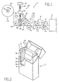
- the portion 1 comprises at least one wrapping line 4 (of the known type), defining an initial section (known and not illustrated) designed to create a wrapper 5 around each group 2 by wrapping a sheet of wrapping material 6 around the group 2, and an end section (also known and not illustrated) designed to place an outer wrap over each wrapper 5, to create rigid, hinged-lid cigarette packets 7 ( Figure 2) or soft packets (not illustrated).
- an initial section known and not illustrated
- an end section also known and not illustrated
- the line 4 is connected to a unit 8 for feeding a continuous band 9 of wrapping material, and a cutting station 10, located between the unit 8 and the line 4, for cutting the band 9 into constant given lengths, each defining a sheet 6 of wrapping material.
- the portion 1 comprises two blades, one fixed 11 and one rotary 12, positioned in the station 10 on opposite sides of the band 9 and designed to operate with one another to cut the band 9 transversally to its longitudinal axis 9a; whilst the unit 8, which is also part of the portion 1, extends along a feed path P, between an unwinding station 13, in which, during operation, the band 9 is unwound from a reel 14 supported by a substantially horizontal rotating shaft 15, and a feed device 16 comprising a pair of motor-powered drive rollers 17, which are parallel with one another and substantially horizontal, rotating at the same tangential speed in opposite directions, and positioned on opposite sides of the band 9, so as to feed the band 9 along the path P, longitudinally aligned with a direction D of feed oriented towards the station 10.
- the feed unit 8 also comprises an embossing device 18, positioned along the path P between the unwinding station 13 and the feed device 16, in turn comprising a pair of motor-powered metal embossing rollers 19, parallel with one another and substantially horizontal, which are located on opposite sides of the band 9, their surfaces worked so as to define an embossing die (known and not illustrated).
- the embossing device 18 also comprises a heating device 20 with temperature regulation (of the known type), designed to heat the two rollers 19 so as to keep the temperature of the surface of the two rollers 19 at a given value (around 50oC).
- a heating device 20 with temperature regulation of the known type
- the band 9 has one paper side 21 (the lower side in Figure 1) and one metal (aluminium) side 22 (the upper side in Figure 1), which respectively correspond with an inner and outer surface of each of the wrappers 5.
- the band 9 was wound over itself during production of the reel 14, after being subjected to an aromatising treatment of the known type, consisting in spraying a menthol aromatising substance onto a central longitudinal strip 21a of the paper side 21 ( Figure 3).
- the width of the strip 21a is equal to the length of the cigarette bodies 3a, so that each sheet of wrapping material 6 has a corresponding aromatised central portion 6a, designed to wrap around the relative cigarette bodies 3a to aromatise the tobacco contained in them (Figure 2), and on the side 21 defines two lateral longitudinal strips 21b and 21c which, for each sheet of wrapping material 6, correspond with two non-aromatised end lateral portions, one of which (not illustrated) is designed to define a base (not illustrated) of the relative wrapper 5, whilst the other, labelled 6b in Figure 2, is designed both to wrap the filters 3b and to define the top 5b of the wrapper 5.
- the feed unit 8 comprises a device 23 for cleaning the metal side 22, located along the path P between the unwinding station 13 and the embossing device 18.
- the cleaning device 23 comprises a metal idle roller 24 which is substantially horizontal and positioned in contact with the metal side 22 of the band 9, and a heating device 25 with temperature regulation (of the known type) designed to heat the roller 24 so that the temperature of the surface of the roller 24 is kept at a given value (around 50oC).
- the cleaning device 23 also comprises a scraping device 26, located in a fixed position immediately downstream of the roller 24 in direction D and on the same side of the band 9 as the roller 24, for removing the above-mentioned menthol aromatising substance from the strip 22a on the metal side 22.
- the scraping device 26 is defined by a metal body 27 with a sharp outer scraping edge 28, which extends from one edge of the band 9 to the other in a direction substantially at right-angles to the direction D and, during operation, makes contact with the metal side 22 of the band 9.
- the body 27 has an internal cavity 29, which has an opening 30 towards the metal side 22 and an opening 31 pneumatically connected to an extractor device 32 which is also part of the cleaning device 23.
- the opening 30 is located immediately upstream of the edge 28, in the direction D, and extends longitudinally alongside the edge 28 near the side 22; whilst the opening 31 is connected to the device 32 by an extractor pipe 33 which extends through a filter 34.
- the cleaning device 23 also comprises a heating device 35 with temperature regulation (of the known type), designed to heat the body 27 so that the temperature of the edge 28 is kept at a given value (around 50oC).
- the band 9 is unwound from the reel 14 and fed by the feed device 16 along the path P, towards the line 4 and through the cutting station 10, in which the band 9 is cut into lengths, each defining a sheet of wrapping material 6.
- the band 9 passes through the device 23 which cleans the metal side 22, then is embossed (in the known way) by the two rollers 19, the surface temperature of which is kept at a value of around 50oC by the heating device 20, so that the aromatising substance on the paper side 21 is in the liquid state at the embossing die, allowing, as indicated above, a correct embossing operation.
- the band 9 is first heated by the roller 24, which brings the local temperature of the band 9 to a value (around 50oC) sufficient to liquefy the aromatising substance on the side 22.
- the metal side 22 of the band 9 then makes contact with the edge 28.
- the aromatising substance removed by the edge 28 is then immediately extracted by the extractor device 32 through the cavity 29, the pipe 33 and the filter 34, inside which the aromatising substance is deposited and solidifies.
- Figure 4 illustrates another embodiment of the cleaning device described above with reference to Figure 1.
- the numerals used to label parts in Figure 4 are the same as in Figure 1, with the exception of those relative to the cleaning device.
- the cleaning device in Figure 4, labelled 23' as a whole, comprises a metal idle roller 24', which is substantially horizontal and positioned so that it is in contact with the metal side 22 of the band 9, and a heating device 25' with temperature regulation (of the known type), designed to heat the roller 24' so that the temperature of the surface of the roller 24' is kept at a given value (around 50oC).
- the cleaning device 23' also comprises a metal scraping roller 36, positioned parallel with the roller 24' close to and downstream of the roller 24' in the same direction D of feed as that of the band 9, and externally limited by a cylindrical surface 37 which touches the metal side 22.
- the roller 36 is motor-powered so that it rotates axially in a direction (clockwise in Figure 4) which allows it to transmit to the surface 37 a sliding motion over the metal side 22 in a direction opposite to direction D, and is designed to co-operate with a counter-roller 38, located opposite the roller 36 on the other side of the band 9 and motor-powered so as to rotate axially in the same direction as the roller 36.
- the cleaning device 23' also comprises a heating device 39 with temperature regulation (of the known type), designed to heat the roller 36 so that the temperature of the surface 37 is kept at a given value (around 50oC).
- the cleaning device 23' also comprises a scraping device 26', located in a fixed position on the side of the roller 36 opposite the band 9 and in contact with the surface 37 of the roller 36.
- the scraping device 26' is defined by a metal body 27', which has a sharp outer scraping edge 28' that extends, in contact with the surface 37, along a generatrix of the surface 37 on the side opposite the band 9.
- the body 27' also has an internal cavity 29', which has an opening 30' towards the surface 37 and an opening 31' pneumatically connected to an extractor device 32' which is also part of the cleaning device 23'.
- the opening 30' is located immediately upstream of the edge 28', relative to the direction of rotation of the roller 36, and extends longitudinally alongside the edge 28 close to the surface 37; whilst the opening 31' is connected to the device 32' by an extractor pipe 33' which extends through a filter 34'.
- the cleaning device 23' comprises a heating device 35' with temperature regulation (of the known type), designed to heat the body 27' so that the temperature of the edge 28' is kept at a given value (around 50oC).
- the band 9 is first heated by the roller 24', which brings the local temperature of the band 9 to a value (around 50oC) sufficient to liquefy the aromatising substance on the side 22.
- the band 9 is then fed between the roller 36 and the counter-roller 38.
- the rotation of the roller 36 causes the surface 37 to scrape the metal side 22 and the consequent removal of the aromatising substance, which is still in the liquid state due to the proximity of the roller 24' and the roller 36.
- the aromatising substance removed from the metal side 22 remains in the liquid state on the surface 37, whose temperature (around 50oC) is determined by the heating device 39, until it reaches the edge 28'.
- the edge 28' whose temperature (around 50oC) is determined by the heating device 35', then removes the aromatising substance from the surface 37, still keeping the aromatising substance in the liquid state.
- the aromatising substance is immediately extracted by the extractor device 32' through the cavity 29', the pipe 33' and the filter 34', inside which the aromatising substance is deposited and solidifies.
Landscapes
- Engineering & Computer Science (AREA)
- Mechanical Engineering (AREA)
- Auxiliary Devices For And Details Of Packaging Control (AREA)
- Wrapping Of Specific Fragile Articles (AREA)
Claims (23)
- Verfahren zum Zuführen in einer Verpackungsmaschine für Produkte einer kontinuierlichen Bahn von Einwickelmaterial, dessen Oberfläche mit einer aromatisierenden Substanz vorimprägniert ist, wobei das Verfahren eine Phase d es A bwickelns der B ahn ( 9) v on einer Spule (14) mit Einwickelmaterial enthält und eine Phase des Zuführens der Bahn (9) an eine Schneidstation (10), wo die Bahn (9) zu Längen geschnitten wird, jede einen Bogen (6) von Einwickelmaterial für ein Produkt (2) bildend; wobei das Verfahren dadurch gekennzeichnet ist, dass es eine Reinigungsphase der Bahn (9) enthält, die das Entfernen der aromatisierenden Substanz von einem gegebenen Abschnitt (22a) der Bahn (9) vorsieht.
- Verfahren nach Patentanspruch 1, dadurch gekennzeichnet, dass die Reinigungsphase einen Vorgang zum Erhitzen der aromatisierenden Substanz enthält, wobei die genannte Substanz im wesentlichen in einen flüssigen Zustand gebracht wird, einen Vorgang zum Entfernen der genannten aromatisierenden Substanz im flüssigen Zustand von dem gegebenen Abschnitt (22a) und einen Vorgang zum Aufnehmen und Abführen der von dem gegebenen Abschnitt (22a) entfernten aromatisierenden Substanz.
- Verfahren nach Patentanspruch 2, dadurch gekennzeichnet, dass der Vorgang des Erhitzens im wesentlichen durch Wärmeleitung erfolgt.
- Verfahren nach Patentanspruch 2 oder 3, dadurch gekennzeichnet, dass der Vorgang des Entfernens im wesentlichen ein Vorgang ist, der das Abschaben des gegebenen Abschnittes (22a) einschliesst.
- Verfahren nach einem beliebigen der Patentansprüche von 2 bis 4, dadurch gekennzeichnet, dass der Vorgang des Aufnehmens und Abführens eine Phase enthält, die das Absaugen der von dem gegebenen Abschnitt (22a) entfernten aromatisierenden Substanz einschliesst.
- Verfahren nach einem beliebigen der Patentansprüche von 1 bis 5, dadurch gekennzeichnet, dass die Bahn (9) eine Papierseite (21) und eine Metallseite (22) hat; wobei sich der gegebene Abschnitt (22a) auf der Metallseite (22) befindet.
- Verfahren nach einem beliebigen der Patentansprüche von 1 bis 6, dadurch gekennzeichnet, dass es eine Phase des Prägens der Bahn (9) enthält; wobei die Reinigungsphase der Prägephase vorausgeht.
- Einheit zum Zuführen in einer Verpackungsmaschine für Produkte einer kontinuierlichen Bahn von Einwickelmaterial, dessen Oberfläche mit einer aromatisierenden Substanz v orimprägniert ist, wobei d ie Einheit (8) Mittel (15) zum Abwickeln der Bahn (9) von einer Spule (14) mit Einwickelmaterial enthält und Mittel (16) zum Zuführen der Bahn (9) an eine Schneidstation (10), wo die Bahn (9) zu Längen geschnitten wird, jede einen Bogen (6) von Einwickelmaterial für ein Produkt (2) bildend; wobei die Einheit (8) dadurch gekennzeichnet ist, dass sie Mittel (23; 23') zum Reinigen der Bahn (9) enthält, und wobei die genannten Mittel dazu bestimmt sind, die aromatisierende Substanz von einem gegebenen Abschnitt (22a) der Bahn (9) zu entfernen.
- Einheit nach Patentanspruch 8, dadurch gekennzeichnet, dass die Reinigungsmittel (23; 23') erste Heizmittel (24, 25; 24', 25') enthalten, dazu bestimmt, die aromatisierende S ubstanz in einen im w esentlichen flüssigen Z ustand zu bringen; sowie Entfernungsmittel (26; 36, 38) zum Entfernen der aromatisierenden Substanz von dem gegebenen Abschnitt (22a); und Mittel (29, 32, 33; 26', 32', 33') zum Aufnehmen und Abführen der von dem gegebenen Abschnitt (22a) entfernten aromatisierenden Substanz.
- Einheit nach Patentanspruch 9, dadurch gekennzeichnet, dass die ersten Heizmittel (24, 25; 24', 25') ein beheiztes Element (24; 24') enthalten, wobei sich das genannte Element wenigstens z um Teil im Kontakt mit der Bahn (9) befindet und dazu bestimmt ist, Hitze auf die Bahn (9) zu übertragen.
- Einheit nach Patentanspruch 10, dadurch gekennzeichnet, dass das Heizelement (24; 24') durch eine Umlenkrolle (24; 24') für die Bahn (9) beschrieben wird; wobei wenigstens die Oberfläche der genannten Rolle (24; 24') aus einem wärmeleitenden Material besteht.
- Einheit nach einem beliebigen der Patentansprüche von 9 bis 11, dadurch gekennzeichnet, dass die Mittel (29, 32, 33; 26', 32' 33') zum Aufnehmen und Abführen Mittel (32; 32') zum Absaugen der von dem gegebenen Abschnitt (22a) entfernten aromatisierenden Substanz enthalten.
- Einheit nach einem beliebigen der Patentansprüche von 9 bis 12, dadurch gekennzeichnet, dass die Mittel (26; 36, 38) zum Entfernen erste Mittel (26; 36, 38) zum Abschaben des gegebenen Abschnittes (22a) enthalten.
- Einheit nach Patentanspruch 13, dadurch gekennzeichnet, dass die ersten Abschabmittel (26) eine scharfe Scha-bekante (28) enthalten, wobei sich die genannte Kante wenigstens an dem gegebenen Abschnitt (22a) mit der Bahn (9) im Kontakt befindet.
- Einheit nach Patentanspruch 14, dadurch gekennzeichnet, dass die genannten ersten Abschabmittel (26) aus einem wärmeleitenden Material bestehen, und zwar wenigstens an der Kante (28); wobei zweite Heizmittel ( 35) vorgesehen sind, u m die Kante (28) auf einer bestimmten Temperatur zu halten.
- Einheit nach Patentanspruch 13, dadurch gekennzeichnet, dass die ersten Abschabmittel (36, 38) eine Schaberolle (36) enthalten, wobei sich die genannte Rolle wenigstens an dem gegebenen Abschnitt (22a) mit der Bahn (9) im Kontakt befindet.
- Einheit nach Patentanspruch 16, dadurch gekennzeichnet, dass wenigstens die Oberfläche der Schaberolle (36) aus einem wärmeleitenden Material besteht; wobei zweite Heizmittel (39) vorgesehen sind, um die Oberfläche (37) der Rolle (36) auf einer bestimmten Temperatur zu halten.
- Einheit nach Patentanspruch 14 oder 15, dadurch gekennzeichnet, dass die Absaugmittel (32) dazu bestimmt sind, mit den ersten Abschabmitteln (26) zusammenzuarbeiten, wobei sie durch einen bestimmten Teil (29) der ersten Abschabmittel (26) die von dem gegebenen Abschnitt (22a) der Bahn (9) entfernte aromatisierende Substanz aufnehmen.
- Einheit nach Patentanspruch 16 oder 17, dadurch gekennzeichnet, dass die Mittel (26', 32', 33') zum Aufnehmen und Abführen zweite Abschabmittel (26') enthalten, wobei die genannten Abschabmittel eine scharfe Schabkante (28') aufweisen, die im Kontakt mit der Rolle (36) angeordnet ist.
- Einheit nach Patentanspruch 19, dadurch gekennzeichnet, dass die zweiten Abschabmittel (26') wenigstens an der Kante (28') aus einem wärmeleitenden Material bestehen; wobei dritte Heizmittel (35') vorgesehen sind, um die Kante (28') auf einer bestimmten Temperatur zu halten.
- Einheit nach Patentanspruch 19 oder 20, dadurch gekennzeichnet, dass die Absaugmittel (32') dazu bestimmt sind, mit den zweiten Abschabmitteln (26') zusammenzuarbeiten, wobei sie durch einen bestimmten Teil (29') der zweiten Abschabmittel (26') die durch die zweiten Abschabmittel (26') entfernte aromatisierende Substanz aufnehmen.
- Einheit nach einem beliebigen der Patentansprüche von 8 bis 21, dadurch gekennzeichnet, dass die Bahn (9) eine Papierseite (21) und eine Metallseite (22) aufweist; wobei sich der genannte bestimmte Abschnitt (22a) der Bahn (9) auf der Metallseite (22) befindet.
- Einheit nach einem beliebigen der Patentansprüche von 8 bis 22, dadurch gekennzeichnet, dass sie Mittel (18) zum Prägen der Bahn (9) enthält, wobei die genannten Mittel in einer vorgegebenen Zuführrichtung (D) der Bahn (9) stromabwärts der Reinigungsmittel (23) angeordnet sind.
Applications Claiming Priority (2)
| Application Number | Priority Date | Filing Date | Title |
|---|---|---|---|
| IT97BO000638A IT1295642B1 (it) | 1997-10-23 | 1997-10-23 | Metodo ed unita' per alimentare in una macchina incartatrice di prodotti un nastro continuo di materiale di incarto pre-impregnato |
| ITBO970638 | 1997-10-23 |
Publications (2)
| Publication Number | Publication Date |
|---|---|
| EP0911261A1 EP0911261A1 (de) | 1999-04-28 |
| EP0911261B1 true EP0911261B1 (de) | 2004-03-03 |
Family
ID=11342612
Family Applications (1)
| Application Number | Title | Priority Date | Filing Date |
|---|---|---|---|
| EP98830606A Expired - Lifetime EP0911261B1 (de) | 1997-10-23 | 1998-10-13 | Verfahren und Einheit zur Reinigung der Oberfläche einer vorimprägnierten Verpackungsmaterialbahn |
Country Status (5)
| Country | Link |
|---|---|
| US (1) | US6095959A (de) |
| EP (1) | EP0911261B1 (de) |
| CN (1) | CN1106984C (de) |
| DE (1) | DE69822064T2 (de) |
| IT (1) | IT1295642B1 (de) |
Cited By (2)
| Publication number | Priority date | Publication date | Assignee | Title |
|---|---|---|---|---|
| WO2026074518A1 (en) * | 2024-10-04 | 2026-04-09 | G.D S.P.A. | Cleaning method for a plant for packaging objects |
| WO2026074520A1 (en) * | 2024-10-04 | 2026-04-09 | G.D S.P.A. | Cleaning method for a plant for packaging groups of objects |
Families Citing this family (8)
| Publication number | Priority date | Publication date | Assignee | Title |
|---|---|---|---|---|
| PE20041044A1 (es) * | 2003-05-23 | 2004-12-30 | Colgate Palmolive Co | Metodo para envolver productos |
| EP1645511B1 (de) * | 2003-07-16 | 2009-10-14 | Japan Tobacco Inc. | Vorrichtung zur zuführung von innenverpackungsmaterial zur verpackung eines zigarettenbündels |
| ITBO20040201A1 (it) * | 2004-04-08 | 2004-07-08 | Gd Spa | Unita' per l'alimentazione ed il taglio in spezzoni di un nastro di materiale di incarto |
| DE102006049111A1 (de) * | 2006-10-18 | 2008-04-30 | Heidelberger Druckmaschinen Ag | Flachbett-Bogenstanzmaschine |
| EP2826618A3 (de) * | 2006-11-08 | 2015-04-08 | Heidelberger Druckmaschinen AG | Faltschachtelklebemaschine zur Herstellung von Faltschachteln aus Zuschnitten |
| JP5693019B2 (ja) * | 2010-03-01 | 2015-04-01 | ユニ・チャーム株式会社 | 回転加工装置 |
| DE102011114522A1 (de) * | 2011-09-29 | 2013-04-04 | Focke & Co. (Gmbh & Co. Kg) | Verfahren und Vorrichtung zum Herstellen einer Verpackung für eine Gruppe rauchbarer Artikel |
| IT202100027116A1 (it) * | 2021-10-21 | 2023-04-21 | Koerber Tech S P A | Apparato per formare un foglio di materiale comprendente sostanze vegetali e/o alcaloidi |
Family Cites Families (11)
| Publication number | Priority date | Publication date | Assignee | Title |
|---|---|---|---|---|
| GB1260118A (en) * | 1968-02-14 | 1972-01-12 | Carreras Ltd | A method of treating a wrapper |
| SE331544B (de) * | 1969-05-30 | 1971-01-04 | Indas Ind Aseptik Ab | |
| US3668980A (en) * | 1970-08-03 | 1972-06-13 | Eastman Kodak Co | Method and apparatus for manufacturing aperture cards |
| DE2416419C2 (de) * | 1974-04-04 | 1984-01-05 | Agfa-Gevaert Ag, 5090 Leverkusen | Vorrichtung zum kontinuierlichen Reinigen von bandförmigen flexiblen Schichtträgern |
| FR2360391A1 (fr) * | 1976-08-05 | 1978-03-03 | Chambon Machines | Machine de decoupage d'une nappe de materiau |
| CH621468A5 (de) * | 1977-04-04 | 1981-02-13 | Burrus & Cie | |
| US4601157A (en) * | 1984-03-15 | 1986-07-22 | The Crowell Corporation | Automatic packaging |
| SE8405106L (sv) * | 1984-10-12 | 1985-07-15 | Solbergs Forseljnings | Sett och utrustning for att tillskera gavelrondeller for emballering av pappersrullar |
| JPH0638665Y2 (ja) * | 1988-05-10 | 1994-10-12 | 日本テトラパック株式会社 | 包装用ウエブの切断装置 |
| DE4114374C2 (de) * | 1991-05-02 | 2003-06-05 | Hauni Werke Koerber & Co Kg | Verfahren und Vorrichtung zum Einhüllen eines Stranges der tabakverarbeitenden Industrie |
| US5618252A (en) * | 1991-07-26 | 1997-04-08 | Machinery Developments Limited | Packaging apparatus |
-
1997
- 1997-10-23 IT IT97BO000638A patent/IT1295642B1/it active IP Right Grant
-
1998
- 1998-10-13 DE DE69822064T patent/DE69822064T2/de not_active Expired - Lifetime
- 1998-10-13 EP EP98830606A patent/EP0911261B1/de not_active Expired - Lifetime
- 1998-10-21 US US09/176,115 patent/US6095959A/en not_active Expired - Fee Related
- 1998-10-22 CN CN98123420A patent/CN1106984C/zh not_active Expired - Fee Related
Cited By (2)
| Publication number | Priority date | Publication date | Assignee | Title |
|---|---|---|---|---|
| WO2026074518A1 (en) * | 2024-10-04 | 2026-04-09 | G.D S.P.A. | Cleaning method for a plant for packaging objects |
| WO2026074520A1 (en) * | 2024-10-04 | 2026-04-09 | G.D S.P.A. | Cleaning method for a plant for packaging groups of objects |
Also Published As
| Publication number | Publication date |
|---|---|
| ITBO970638A1 (it) | 1999-04-23 |
| DE69822064D1 (de) | 2004-04-08 |
| US6095959A (en) | 2000-08-01 |
| CN1106984C (zh) | 2003-04-30 |
| EP0911261A1 (de) | 1999-04-28 |
| IT1295642B1 (it) | 1999-05-24 |
| CN1219489A (zh) | 1999-06-16 |
| ITBO970638A0 (it) | 1997-10-23 |
| DE69822064T2 (de) | 2004-09-16 |
Similar Documents
| Publication | Publication Date | Title |
|---|---|---|
| EP0911261B1 (de) | Verfahren und Einheit zur Reinigung der Oberfläche einer vorimprägnierten Verpackungsmaterialbahn | |
| KR101514850B1 (ko) | 튜브 롤링 장치 | |
| CA2333625C (en) | Package provided with a coupon and method for obtaining said package | |
| KR20140062517A (ko) | 끽연류 및 그 제작 | |
| EA017706B1 (ru) | Устройство и способ нанесения накладок | |
| JP3411082B2 (ja) | チップペーパ用糊転写装置 | |
| EP1645511B1 (de) | Vorrichtung zur zuführung von innenverpackungsmaterial zur verpackung eines zigarettenbündels | |
| JP2022515109A (ja) | タバコ産業の管状セグメントを製造するための機械 | |
| EP1358808B1 (de) | Kräuseleinrichtung | |
| US5248375A (en) | Apparatus for applying adhesive to webs to wrapping material in tobacco processing machines | |
| JPH10230552A (ja) | パッケージ、特に、紙巻き煙草パケットのグループおよびこれを製造する方法 | |
| CA1213809A (en) | Smoking articles | |
| DE19644079A1 (de) | Vorrichtung zum Herstellen von Verpackungen aus dünnem Verpackungsmaterial | |
| US9988164B2 (en) | Method and device for producing a package for a group of smokable articles | |
| JPH04279415A (ja) | シガレット束の頂部の露出された箔が明白な折り目のない平坦である方法 | |
| EP0790782B1 (de) | Verfahren und einrichtung zum einwickeln eines stranges aus rauchmaterial | |
| US3518999A (en) | Mouthpiece tobacco articles | |
| CA1162818A (en) | Device for applying filters to cigarettes | |
| WO2018163064A1 (en) | Unit and method for separating plugwraps and applying them to rod-shaped smoking articles | |
| SU1414309A3 (ru) | Способ изготовлени курительных изделий | |
| GB2293817A (en) | Fabrication of folded coupons in a packaging machine | |
| EP0021788B1 (de) | Verfahren zur Herstellung von Zigarren und ähnlichen Tabaksartikeln und Apparat zum Herstellen von Umhüllungen nach diesem Verfahren | |
| EP0021789B1 (de) | Verfahren zur Herstellung von Zigarren und ähnlichen Tabaksartikeln und Apparat zur Durchführung dieses Verfahrens | |
| US3119211A (en) | Feeding of webs of material | |
| GB1604347A (en) | Cigarette manufacture |
Legal Events
| Date | Code | Title | Description |
|---|---|---|---|
| PUAI | Public reference made under article 153(3) epc to a published international application that has entered the european phase |
Free format text: ORIGINAL CODE: 0009012 |
|
| AK | Designated contracting states |
Kind code of ref document: A1 Designated state(s): DE FR GB IT |
|
| AX | Request for extension of the european patent |
Free format text: AL;LT;LV;MK;RO;SI |
|
| 17P | Request for examination filed |
Effective date: 19990611 |
|
| AKX | Designation fees paid |
Free format text: DE FR GB IT |
|
| GRAP | Despatch of communication of intention to grant a patent |
Free format text: ORIGINAL CODE: EPIDOSNIGR1 |
|
| GRAS | Grant fee paid |
Free format text: ORIGINAL CODE: EPIDOSNIGR3 |
|
| GRAA | (expected) grant |
Free format text: ORIGINAL CODE: 0009210 |
|
| RAP1 | Party data changed (applicant data changed or rights of an application transferred) |
Owner name: G.D S.P.A. |
|
| AK | Designated contracting states |
Kind code of ref document: B1 Designated state(s): DE FR GB IT |
|
| REG | Reference to a national code |
Ref country code: GB Ref legal event code: FG4D |
|
| REF | Corresponds to: |
Ref document number: 69822064 Country of ref document: DE Date of ref document: 20040408 Kind code of ref document: P |
|
| ET | Fr: translation filed | ||
| PLBE | No opposition filed within time limit |
Free format text: ORIGINAL CODE: 0009261 |
|
| STAA | Information on the status of an ep patent application or granted ep patent |
Free format text: STATUS: NO OPPOSITION FILED WITHIN TIME LIMIT |
|
| 26N | No opposition filed |
Effective date: 20041206 |
|
| PGFP | Annual fee paid to national office [announced via postgrant information from national office to epo] |
Ref country code: IT Payment date: 20061031 Year of fee payment: 9 |
|
| REG | Reference to a national code |
Ref country code: FR Ref legal event code: ST Effective date: 20080630 |
|
| PGFP | Annual fee paid to national office [announced via postgrant information from national office to epo] |
Ref country code: FR Payment date: 20061017 Year of fee payment: 9 |
|
| PG25 | Lapsed in a contracting state [announced via postgrant information from national office to epo] |
Ref country code: FR Free format text: LAPSE BECAUSE OF NON-PAYMENT OF DUE FEES Effective date: 20071031 |
|
| PG25 | Lapsed in a contracting state [announced via postgrant information from national office to epo] |
Ref country code: IT Free format text: LAPSE BECAUSE OF NON-PAYMENT OF DUE FEES Effective date: 20071013 |
|
| PGFP | Annual fee paid to national office [announced via postgrant information from national office to epo] |
Ref country code: DE Payment date: 20091028 Year of fee payment: 12 |
|
| PGFP | Annual fee paid to national office [announced via postgrant information from national office to epo] |
Ref country code: GB Payment date: 20091026 Year of fee payment: 12 |
|
| GBPC | Gb: european patent ceased through non-payment of renewal fee |
Effective date: 20101013 |
|
| PG25 | Lapsed in a contracting state [announced via postgrant information from national office to epo] |
Ref country code: GB Free format text: LAPSE BECAUSE OF NON-PAYMENT OF DUE FEES Effective date: 20101013 |
|
| REG | Reference to a national code |
Ref country code: DE Ref legal event code: R119 Ref document number: 69822064 Country of ref document: DE Effective date: 20110502 |
|
| PG25 | Lapsed in a contracting state [announced via postgrant information from national office to epo] |
Ref country code: DE Free format text: LAPSE BECAUSE OF NON-PAYMENT OF DUE FEES Effective date: 20110502 |