EP0911268B1 - Conteneur repliable - Google Patents
Conteneur repliable Download PDFInfo
- Publication number
- EP0911268B1 EP0911268B1 EP98308162A EP98308162A EP0911268B1 EP 0911268 B1 EP0911268 B1 EP 0911268B1 EP 98308162 A EP98308162 A EP 98308162A EP 98308162 A EP98308162 A EP 98308162A EP 0911268 B1 EP0911268 B1 EP 0911268B1
- Authority
- EP
- European Patent Office
- Prior art keywords
- wall
- container
- walls
- projection
- base
- Prior art date
- Legal status (The legal status is an assumption and is not a legal conclusion. Google has not performed a legal analysis and makes no representation as to the accuracy of the status listed.)
- Expired - Lifetime
Links
Images




Classifications
-
- B—PERFORMING OPERATIONS; TRANSPORTING
- B65—CONVEYING; PACKING; STORING; HANDLING THIN OR FILAMENTARY MATERIAL
- B65D—CONTAINERS FOR STORAGE OR TRANSPORT OF ARTICLES OR MATERIALS, e.g. BAGS, BARRELS, BOTTLES, BOXES, CANS, CARTONS, CRATES, DRUMS, JARS, TANKS, HOPPERS, FORWARDING CONTAINERS; ACCESSORIES, CLOSURES, OR FITTINGS THEREFOR; PACKAGING ELEMENTS; PACKAGES
- B65D11/00—Containers having bodies formed by interconnecting or uniting two or more rigid, or substantially rigid, components made wholly or mainly of plastics material
- B65D11/18—Containers having bodies formed by interconnecting or uniting two or more rigid, or substantially rigid, components made wholly or mainly of plastics material collapsible, i.e. with walls hinged together or detachably connected
- B65D11/1833—Containers having bodies formed by interconnecting or uniting two or more rigid, or substantially rigid, components made wholly or mainly of plastics material collapsible, i.e. with walls hinged together or detachably connected whereby all side walls are hingedly connected to the base panel
Definitions
- the present invention relates to containers and in particular, to collapsible containers.
- Collapsible containers allow the containers to be stored more compactly when not in use.
- the invention provides a collapsible container comprising a base, a first wall hingedly attached to the base to fold down over the base when the container is collapsed and a second wall hingedly attached to the base to fold down over the first wall when the first wall is folded over the base, the adjacent edges of the first and second walls comprising engaging formations which engage when the container is in the constructed condition, and characterised in that the hinge arrangement between the first wall and the base is arranged to accommodate the engaging formations of the second wall below the uppermost level of the first wall when the container is collapsed.
- the engaging formations are intermeshable.
- the engaging formations of the second wall are preferably provided on a flange projecting from the face of the wall whereby, when the engaging formations are accommodated by the hinge arrangement, the wall face lies against or adjacent the upper face of the collapsed first wall.
- the hinge arrangement between the first wall and the base preferably comprises interleaved knuckles, the knuckles being adapted to receive the engaging formations.
- the knuckles of the base are preferably adapted to receive the engaging formations.
- the knuckles may comprise recesses for receiving the engaging formations.
- the spacing of the knuckles corresponds with the spacing of the engaging formations, whereby each engaging formation is received in a corresponding knuckle.
- the knuckles are preferably regularly spaced.
- the engaging formations may be intermeshable castellations.
- the engaging formations may comprise retention means operable to retain the castellations intermeshed.
- the retention means may comprise a projection on the second wall, past which a part of the first wall must be forced to allow the first wall to reach or leave the erect position.
- the projection is preferably resilient.
- One or both walls may be deformable to allow the first wall to move.
- the projection is preferably carried by the second wall.
- the projection is preferably a rib extending along the second wall and substantially parallel to the first wall when the first wall is in the erect position.
- retaining means are associated with the second wall, operable to retain the second wall against folding down while the first wall is moved up or down.
- the second wall is preferably retained substantially in the erect position.
- the retaining means may be associated with the hinge connection to the base.
- the hinge arrangement preferably comprises interleaved knuckles on the wall and on the base, at least one knuckle having a projection which engages a part hinged thereto, to retain the said part against movement.
- the said part may comprise resilience by which the part may be forced past the projection.
- the walls are formed to co-operate when the second wall has been raised and as the first wall is raised to the erect position, the co-operation serving to push the second wall beyond the erect position to provide clearance for the first wall to reach the erect position, and the second wall thereafter returning to the erect position.
- the co-operation may be provided by a projection on one wall, which engages the other wall as the walls move relative to each other.
- the projection is preferably provided on the second wall.
- the projection may engage the edge of the first wall.
- the projection comprises a leading edge and a slide face, the leading edge providing a cam action to push the second wall beyond the erect position as the edge of the first wall engages the leading edge, and the slide face providing a surface along which the edge of the first wall slides as the first wall moves to the erect position, the first wall moving clear of the projection as the first wall reaches the erect position, thereby allowing the second wall to move back to the erect position.
- the container further comprises a lock arrangement carried by at least one wall and operable to lock an edge of the said one wall to an adjacent wall when the walls are in their erect positions, the lock means being manually releasable from a location remote from the said edge.
- a lock arrangement carried by at least one wall and operable to lock an edge of the said one wall to an adjacent wall when the walls are in their erect positions, the lock means being manually releasable from a location remote from the said edge.
- the lock arrangement may comprise a locking bar retractable to release the adjacent wall.
- the locking bar is preferably resiliently biased to the advanced position.
- the lock arrangement may comprise a manually operable control member mechanically linked to retract the locking bar.
- the control member is preferably connected to one end of an elongate bowed member having a second end fixed in position, the locking bar being connected to the bowed member between the ends thereof, whereby the control member is moveable to cause the bowed member to change shape, preferably to straighten, and thereby to move the locking bar.
- the locking bar is connected to the bowed member through an intermediate portion hingedly connected to the locking bar and the bowed member.
- the control member is preferably located at a handle formation on the carrying wall.
- Each second wall preferably carries a lock arrangement as aforesaid.
- the or each lock arrangement may lock both edges of the carrying wall as aforesaid.
- the container comprises two opposed first walls and two opposed second walls, both ends of the first and second walls being provided with engaging formations as aforesaid, and both first walls having hinge arrangements as aforesaid.
- the second walls may each carry a stacking bar, the stacking bars having a stacking position which, when the container is in the constructed condition, provides a stacking support for the base of a like container, whereby to frorm a stack of containers.
- the hinge axis of the or each second wall is preferably substantially at or above the plane of the upper surface of the first wall when collapsed.
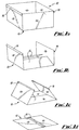
- Figs. 1a to 1d show a container 10 having a base 12, two relatively long first walls 14 and two relatively short second walls 16. (Alternatively, the walls 16 could be longer than the walls 14).
- the first walls 14 are hingedly attached along their lower edge to the base 12 to fold down over the base when the container is collapsed.
- Fig. 1a shows the fully constructed container and
- Fig. 1b shows its condition after this collapsing movement of the first walls has commenced.
- Fig. 1c the first walls 14 have fully collapsed over the base 12.
- the second walls 16 are also hingedly attached to the base 12 to fold down over the first walls 14 once the first walls 14 have folded over the base 12. As can be seen, this collapsing movement commences in Fig. 1c, after the first walls 14 have fully collapsed. This results in the final condition shown in Fig. 1d, in which all four walls are lying over each other and the base, to leave a collapsed, flat container.
- a stacking bar 18 may be provided, preferably on the second walls 16 so that the bar 18 can remain mounted on the second wall 16 substantially without interfering with the collapsing process.
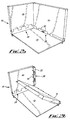
- Fig. 2a views one corner of the container 10 in the constructed condition, i.e. before the walls have begun to collapse.
- the first wall hinges in to the position shown in Fig. 2b.
- engagement between the adjacent edges of the walls 14, 16 must be released.
- the engaging formations on the wall 16 are visible in Fig. 2b as a vertical row of castellations 20 formed along a flange 22 which projects out of the plane of the wall 16, toward the wall 14.
- a complementary line of castellations 24, visible for instance in Fig. 2c, is provided along the edge of the wall 14.
- the castellations 20, 24 engage each other, for instance by snap-fitting, when brought together in the constructed condition of the container 10, to hold the walls 14, 16 in that condition.
- the wall 14 has reached its fully collapsed position, lying flat on the base 12. This is arranged by appropriate design of the hinge arrangement at 26, primarily by spacing the hinge axis above the base 12 by substantially one half of the thickness of the wall 14.
- the second wall 16 can begin to collapse, folding down over the first wall 14 to an intermediate position shown in Fig. 2d.
- the axis of the hinge arrangement 28 for the second wall 16 is higher than that of the hinge arrangement 26.
- the hinge axis of the hinge arrangement 28 is spaced above the upper surface of the wall 14 (when collapsed) by substantially one half of the thickness of the wall 16, so that the wall 16 can be folded down to lie flat against the exposed surface of the wall 14 when fully collapsed.
- Fig. 2e shows the wall 16 approaching that final position, which is shown in Fig. 2f.
- the hinge arrangement 26 is visible in Fig. 2d and includes knuckles 30 along the bottom edge of the wall 14 and interleaved with knuckles 32 upstanding from the base 12.
- the knuckles 32 are hollow. They have recesses open from above. These recesses are positioned to receive prominences 34 of the castellation 20 when the wall 16 fully collapses, at which position the knuckles 14 will be received in the recesses of the castellations 20. Consequently, the line of hinge knuckles 30, 32 intermesh with the castellation 20.
- this formation of the knuckles 32 ensures that the wall 16 can fold flat against the wall 14, without needing to be spaced above it to accommodate the means for engagement between the walls when constructed.
- the formations of the castellations 20 and the formations of the hinge 16 are positioned to miss each other, they can each independently be optimised to their function of secure attachment and secure hinging, substantially without that process of optimisation affecting the corresponding process in relation to the other function.
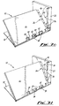
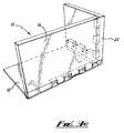
- FIG. 3d The remaining figures show the sequence by which the walls 14, 16 are moved from the collapsed position (Fig. 2f) to the constructed condition (Fig. 3d), when viewed from outside the container. Essentially, the sequence described above in relation to Figs. 2a to 2f is reversed.
- the wall 16 is hinged up through the intermediate position of Fig. 3a to the vertical position of Fig. 3b. It can be seen in Fig. 3b that the castellations 20 have moved clear of the recesses 36 in the hinge 26, and are now exposed, ready to receive the castellations 24 when the wall 14 hinges up from the position shown in Fig. 3b, through the intermediate position shown in Fig. 3c, to the position shown in Fig.
- Figs. 2 and 3 have shown only one corner of the container, for reasons of clarity of drawing and description. However, it will be readily apparent to the skilled man how the arrangement can be adapted to provide engaging formations of the same type at each corner of a container of the type illustrated in Fig. 1, so that in the constructed condition, the container is held securely at each of the four corners, while in the collapsed condition (Fig. 1d) the four sets of castellations 20 (one set at each end of each wall 16) are intermeshed with one or other hinge 16.
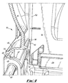
- Fig. 4 shows a hinge arrangement, particularly for use along the lower edge of the second walls 16.
- the arrangements show in Fig. 4 correspond closely with the arrangements described above, but the embodiment shown in Fig. 4 is more highly styled for aesthetic and other reasons. However, the same numerals are used for corresponding items, when appropriate.
- the base 12 of the container has upstanding knuckles 32, as has been described. Neighbouring knuckles 32 are connected by pivot pins 40 to allow intervening knuckles of the wall 16 to complete the hinge arrangement.
- the top edge 42 of the knuckles 32 has a curved shape centred on the pins 40, but interrupted by a projection 44 near the outer face of the knuckle 32 and which defines a small catch location 46 beyond the projection 44.
- the wall 16 carries along its lower edge a resilient valance 48 which, when the wall is in the erect condition shown in Fig. 4, covers the open top of the knuckles 32 and is generally complimentary in profile to the profile of the top edge 42.
- the outer edge of the valance 48 forms a bead 50 which can locate behind the projection 44, in the catch location 46 when the wall is in the erect position.
- the resilience of the valance 48 will tend to retain the bead 50 in the location 46, thus retaining the wall in the position shown.
- the bead 50 will slide along the edge 42 until encountering the projection 44, the valance 48 will flex to allow the bead 50 to pass over the projection 44, and the bead 50 will then snap down into the catch location 46, thereafter holding the wall 16 against falling back over the base 12. Once the walls 16 have snapped into position in this way, the user no longer needs to hold them up, allowing both hands then to be used to pull the walls 14 up to their erect position.
- the walls 14 can be retained in their erect position in various ways, including snap-fitting as has been described.
- One example is illustrated in Figs. 5 to 7. Again, like numerals have been used for corresponding features.
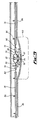
- the wall 16 carries a rib 52 which (with the wall 16 in the erect condition) extends vertically up virtually the entire height of the wall 16, spaced slightly from the castellations 20 to define a vertical slot 54 therebetween (Fig. 6).
- the rib 52 represents an obstruction past which the edge of the wall 14 must move in order to reach the erect position, in which the edge of the wall 14 is located in the slot 54.
- the rib 52 may be made of resilient material, to allow the wall to be forced past, or there may be other resilience (as described below) which allows the wall 16 to be forced further out, past its erect position until the edge of the wall 14 has reached the slot 54, at which time the wall 16 can relax back to the erect position.
- the wall 14 may move past the rib 52 by virtue of the wall 14 being deformed out of a planar condition, to a curved condition 56 illustrated in Fig. 6.
- the edge encounters the ridge 52, is obstructed, and bows until being freed sufficiently to pass into the slot 54.
- the wall then straightens.
- the ribs 52 will retain the walls in the erect positions until the wall 14 is pushed or pulled inwardly sufficiently to curve to the position indicated at 58 in Fig. 6, at which the wall 14 has bowed sufficiently to free its edges from the slot 54, allowing the walls 14 to be folded down.
- this arrangement can be made to allow a wall 14 to be locked in the erect position more easily than it can be moved away from that position for collapsing the container.
- FIG. 8 corresponds closely with Fig. 2a, and illustrates a handle 60 formed in the wall 14 as an aperture.
- a control member indicated schematically at 62 extends across the width of the wall 14, reaching both edges, and having a control button accessible to a users finger when the hand is in the handle aperture 60.
- the control member 62 is illustrated in more detail in Fig. 9.
- the control button 64 has a finger pad 66 behind which a bar 68 extends.
- the remote end of the bar 68 is attached to one end of each of two bowed members 70, the other ends of which form eyes 72 located over pins 74 to fix those ends in position. Accordingly, pushing the button 64 to raise the bar 68 pushes the free ends of the members 70 away from the pins 74, causing the bowed members 70 to begin to straighten.
- elongate locking bars 76 extend away to the edges of the walls 14.
- the ends of the bars 76 proximate the bowed members 70 are connected to a point midway along the corresponding member 70 through a short intermediate member 78 hinged at 80 to the bowed member 70, and at 82 to the locking bar 76.
- pressing the button 64 causes the bowed members 70 to pull the locking bars 76 inboard of the wall 14, while releasing the button 64 allows the arrangement to relax, with the locking bars 76 projecting outboard of the walls 14.
- the button 64, bar 68, members 70, 76 and 78 can be formed as a single plastics moulded item, having sufficient inherent resilience to bias the locking bars 76 to the locked position (shown in Fig. 9).
- Movement of the locking bars 76 is axial, guided by guides, pins or other guide formations 84. These may be provided directly on the wall, or the complete latch arrangement could be a sub-assembly for attachment to the wall 14.
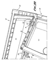
- a short rib 90 is provided on the wall 16, near the corner of the container and close to the hinges.
- the rib 90 is shown in Fig. 10 and also partially in Fig. 4.
- the rib 90 is generally elongate, having a slide surface 92 along almost the whole of its length, preceded by a sloping leading edge at the end remote from the corner of the container.
- the purpose of the rib 90 is to engage the edge of the wall 14 as the wall 14 moves past the rib 90 to approach its erect position.
- This arrangement ensures that the upper corner of the wall 14 does not catch against any formations on the wall 16 (particularly along its upper edge) by providing clearance while the rib 90 is active, but ensures that the wall 16 is in the final erect position just as the wall 14 reaches its erect position, so that the various castellations described above can correctly locate with each other.
- the container can preferably be manufactured from synthetic plastics material, preferably by injection moulding.
Landscapes
- Engineering & Computer Science (AREA)
- Mechanical Engineering (AREA)
- Rigid Containers With Two Or More Constituent Elements (AREA)
Claims (39)
- Conteneur démontable (10) comprenant une base (12), une première paroi (14) fixée de manière articulée à la base pour se replier sur la base lorsque le conteneur est démonté et une seconde paroi (16) fixée de manière articulée à la base pour se replier sur la première paroi lorsque la première paroi est repliée sur la base, les bords adjacents des première et seconde parois comprenant des formations de mise en prise (20, 24) qui se mettent en prise lorsque le conteneur est dans la condition montée, et caractérisé en ce que le dispositif de charnière (26) entre la première paroi et la base est agencé pour recevoir les formations de mise en prise de la seconde paroi au dessous du niveau le plus élevé de la première paroi lorsque le conteneur est démonté.
- Conteneur (10) selon la revendication 1, caractérisé en ce que les formations de mise en prise (20, 24) peuvent se mettre en prise mutuellement.
- Conteneur (10) selon la revendication 1, caractérisé en ce que les formations de mise en prise (20, 24) de la seconde paroi (16) sont prévues sur un rebord (22) faisant saillie à partir de la face de la paroi moyennant quoi, quand les formations de mise en prise sont reçues par le dispositif de charnière (26), la face de la paroi se trouve contre ou adjacente à la face supérieure de la première paroi démontée (14).
- Conteneur (10) selon l'une quelconque des revendications précédentes, caractérisé en ce que le dispositif de charnière (26) entre la première paroi (14) et la base comprend des articulations intercalaires (30, 32), les articulations étant adaptées pour recevoir les formations de mise en prise (20).
- Conteneur (10) selon la revendication 4, caractérisé en ce que les articulations (32) de la base (12) sont adaptées pour recevoir les formations de mise en prise (20).
- Conteneur (10) selon la revendication 4 ou 5, caractérisé en ce que les articulations (32) comprennent des renfoncements (36) pour recevoir les formations de mise en prise (20).
- Conteneur (10) selon l'une quelconque des revendications 4 à 6, caractérisé en ce que l'espacement des articulations (32) correspond à l'espacement des formations de mise en prise (20), moyennant quoi chaque formation de mise en prise est reçue dans une articulation correspondante.
- Conteneur (10) selon l'une quelconque des revendications 4 à 7, caractérisé en ce que les articulations (32) sont espacées de manière régulière.
- Conteneur (10) selon l'une quelconque des revendications précédentes, caractérisé en ce que les formations de mise en prise (20, 24) sont des éléments crénelés pouvant se mettre en prise mutuellement.
- Conteneur (10) selon la revendication 9, caractérisé en ce que les formations de mise en prise (20, 24) comprennent des moyens de retenue (52, 54) pouvant fonctionner pour retenir les éléments crénelés (20, 24) mis en prise mutuellement.
- Conteneur (10) selon la revendication 10, caractérisé en ce que les moyens de retenue (52, 54) comprennent une saillie (52) sur la seconde paroi (16), au-delà de laquelle une partie de la première paroi (14) doit être forcée pour permettre à la première paroi d'atteindre ou de quitter la position droite.
- Conteneur (10) selon la revendication 11, caractérisé en ce que la saillie (52) est résiliente.
- Conteneur (10) selon la revendication 11 ou 12, caractérisé en ce qu'une ou les deux parois (14, 16) sont déformables pour permettre le mouvement de la première paroi (14).
- Conteneur (10), selon la revendication 11, 12 ou 13, caractérisé en ce que la saillie (52) est supportée par la seconde paroi (16).
- Conteneur (10) selon l'une quelconque des revendications 11 à 14, caractérisé en ce que la saillie (52) est une nervure s'étendant le long de la seconde paroi (16).
- Conteneur (10) selon la revendication 15, caractérisé en ce que la nervure (52) s'étend le long de la seconde paroi (16) et est sensiblement parallèle à la première paroi (14) lorsque la première paroi est dans la position droite.
- Conteneur (10) selon l'une quelconque des revendications précédentes, caractérisé en ce que des moyens pour la retenue (44, 50) sont associés à la seconde paroi (16), pouvant fonctionner pour retenir la seconde paroi contre le pliage alors que la première paroi (14) est déplacée vers le haut ou vers le bas.
- Conteneur (10) selon la revendication 17, caractérisé en ce que la seconde paroi (16) est retenue sensiblement dans la position droite.
- Conteneur (10) selon la revendication 17 ou 18, caractérisé en ce que les moyens pour la retenue (44, 50) sont associés au raccordement de charnière (28) à la base (12).
- Conteneur (10) selon la revendication 19, caractérisé en ce que le dispositif de charnière (28) comprend des articulations intercalaires sur la paroi (16) et sur la base (12), au moins une articulation ayant une saillie (44) qui met en prise une partie (16) articulée par rapport à celle-ci, pour retenir ladite partie contre le mouvement.
- Conteneur selon la revendication 20, caractérisé en ce que ladite partie (16) comprend de la résilience (48) avec laquelle la partie peut être forcée au-delà de la saillie (44).
- Conteneur (10) selon l'une quelconque des revendications précédentes, caractérisé en ce que les parois (14, 16) sont formées pour coopérer lorsque la seconde paroi (16) a été levée et lorsque la première paroi (14) est levée vers la position droite, la coopération servant à pousser la seconde paroi au-delà de la position droite pour fournir un jeu afin que la première paroi atteigne la position droite, et que la seconde paroi revienne ensuite à la position droite.
- Conteneur (10) selon la revendication 22, caractérisé en ce que la coopération est fournie par une saillie (52) sur une paroi (16), qui met en prise l'autre paroi (14) lorsque les parois se déplacent l'une par rapport à l'autre.
- Conteneur (10) selon la revendication 23, caractérisé en ce que la saillie (52) est prévue sur la seconde paroi (16).
- Conteneur (10) selon la revendication 23 ou 24, caractérisé en ce que l'autre paroi (14) est la première paroi, la saillie (52) mettant en prise le bord de la première paroi.
- Conteneur (10) selon la revendication 23, 24 ou 25, caractérisé en ce que la saillie (52) comprend une bord d'attaque et une face de coulissement, le bord d'attaque fournissant une action de came pour pousser la seconde paroi (16) au-delà de la position droite lorsque le bord de la première paroi (14) met en prise le bord d'attaque, et la face de coulissement fournissant une surface le long de laquelle le bord de la première paroi coulisse lorsque la première paroi se déplace vers la position droite, la première paroi se dégageant de la saillie lorsque la première paroi atteint la position droite, permettant ainsi à la seconde paroi de retourner à la position droite.
- Conteneur (10) selon l'une quelconque des revendications précédentes, caractérisé par un dispositif de verrouillage (62) supporté par au moins une paroi (16) et pouvant fonctionner pour verrouiller un bord de ladite une paroi sur une paroi adjacente (14) lorsque les parois sont dans leurs positions droites, les moyens de verrouillage pouvant être manuellement dégagés d'un emplacement (60) à distance dudit bord.
- Conteneur (10) selon la revendication 27, caractérisé en ce que le dispositif de verrouillage (62) comprend une barre de verrouillage (76) rétractable pour libérer la paroi adjacente.(14).
- Conteneur (10) selon la revendication 28, caractérisé en ce que la barre de verrouillage (76) est sollicitée de manière résiliente vers la position avancée.
- Conteneur (10) selon la revendication 28 ou 29, caractérisé en ce que le dispositif de verrouillage (62) comprend un élément de commande (64) pouvant fonctionner manuellement, relié mécaniquement pour rétracter la barre de verrouillage (76).
- Conteneur (10) selon la revendication 30, caractérisé en ce que l'élément de commande (64) est raccordé à une première extrémité d'un élément incliné allongé (70) ayant une seconde extrémité (72) fixée en position, la barre de verrouillage (76) étant raccordée à l'élément incliné entre ses extrémités, moyennant quoi l'élément de commande est déplaçable pour provoquer le changement de forme de l'élément incliné, de préférence pour le redresser et déplacer ainsi la barre de verrouillage.
- Conteneur (10) selon la revendication 31, caractérisé en ce que l'élément de commande (64) est déplaçable pour provoquer le redressement de l'élément incliné (70).
- Conteneur (10) selon la revendication 31 ou 32, caractérisé en ce que la barre de verrouillage (76) est raccordée à l'élément incliné (70) par le biais d'une partie intermédiaire (78) raccordée de manière articulée à la barre de verrouillage (76) et à l'élément incliné (70).
- Conteneur (10) selon l'une quelconque des revendications 31 à 33, caractérisé en ce que l'élément de commande (64) est situé au niveau d'une formation de poignée (60) sur la paroi porteuse (16).
- Conteneur (10) selon l'une quelconque des revendications 27 à 34, caractérisé en ce que chaque seconde paroi (16) supporte un dispositif de verrouillage (62), comme mentionné précédemment.
- Conteneur (10) selon l'une quelconque des revendications 27 à 35, caractérisé en ce que le ou chaque dispositif de verrouillage (62) verrouille les deux bords de la paroi porteuse (16), comme mentionné précédemment.
- Conteneur (10) selon l'une quelconque des revendications précédentes, caractérisé par deux premières parois opposées (14) et deux secondes parois opposées (16), les deux extrémités des premières et secondes parois étant pourvues de formations de mise en prise (20, 24), comme mentionné précédemment, et les deux premières parois (14) étant dotées de dispositifs de charnière (26), comme mentionné précédemment.
- Conteneur (10) selon la revendication 37, caractérisé en ce que les secondes parois (16) supportent chacune une barre d'empilage (18), les barres d'empilage ayant une position d'empilage qui, lorsque le conteneur est dans la condition montée, fournit un support d'empilage pour la base d'un conteneur similaire afin de former une pile de conteneurs.
- Conteneur (10) selon l'une quelconque des revendications précédentes, caractérisé en ce que l'axe de charnière de la ou chaque seconde paroi (16) est sensiblement au niveau de ou au dessus du plan de la surface supérieure de la première paroi (14) lorsqu'elle est démontée.
Applications Claiming Priority (2)
| Application Number | Priority Date | Filing Date | Title |
|---|---|---|---|
| GBGB9721129.6A GB9721129D0 (en) | 1997-10-07 | 1997-10-07 | Container |
| GB9721129 | 1997-10-07 |
Publications (2)
| Publication Number | Publication Date |
|---|---|
| EP0911268A1 EP0911268A1 (fr) | 1999-04-28 |
| EP0911268B1 true EP0911268B1 (fr) | 2004-08-11 |
Family
ID=10820089
Family Applications (1)
| Application Number | Title | Priority Date | Filing Date |
|---|---|---|---|
| EP98308162A Expired - Lifetime EP0911268B1 (fr) | 1997-10-07 | 1998-10-07 | Conteneur repliable |
Country Status (7)
| Country | Link |
|---|---|
| US (1) | US6138851A (fr) |
| EP (1) | EP0911268B1 (fr) |
| CA (1) | CA2249677A1 (fr) |
| DE (1) | DE69825540T2 (fr) |
| ES (1) | ES2226073T3 (fr) |
| GB (2) | GB9721129D0 (fr) |
| NO (1) | NO984679L (fr) |
Families Citing this family (33)
| Publication number | Priority date | Publication date | Assignee | Title |
|---|---|---|---|---|
| US6918502B1 (en) | 1997-12-19 | 2005-07-19 | Rehrig Pacific Company | Collapsible container |
| DE19917771A1 (de) * | 1999-04-20 | 2000-11-02 | Bekuplast Gmbh | Transport- und Lagerbehälter mit einklappbaren Seitenwänden |
| JP3274857B2 (ja) | 2000-04-10 | 2002-04-15 | 岐阜プラスチック工業株式会社 | 折り畳みコンテナ |
| SE0103685D0 (sv) * | 2001-11-05 | 2001-11-05 | Arca Systems Ab | Collapsible container |
| US6938772B2 (en) | 2002-06-04 | 2005-09-06 | Rehrig Pacific Company | Portable storage container |
| JP4074533B2 (ja) * | 2003-03-06 | 2008-04-09 | セイコーエプソン株式会社 | 電気光学装置及び電子機器 |
| US7195127B2 (en) * | 2003-05-13 | 2007-03-27 | Rehrig Pacific Company | Collapsible container |
| US7823728B2 (en) | 2005-03-04 | 2010-11-02 | Rehrig Pacific Company | Storage container with support structure for multiple levels of nesting |
| US20060213150A1 (en) * | 2005-03-24 | 2006-09-28 | Sonon James A | Method for product handling using a configurable display container |
| US7484621B2 (en) | 2005-09-09 | 2009-02-03 | Rehrig Pacific Company | Tray |
| SE529476C2 (sv) * | 2005-11-21 | 2007-08-21 | Molander Tech Ab | Hopfällbar låda |
| US7840180B2 (en) * | 2006-12-22 | 2010-11-23 | The Boeing Company | Molniya orbit satellite systems, apparatus, and methods |
| US8261923B2 (en) * | 2008-04-22 | 2012-09-11 | Otto Industries North America, Inc. | Collapsible container |
| US8905254B2 (en) * | 2008-06-23 | 2014-12-09 | Mechana Cc | Transport of goods |
| CA2741242C (fr) | 2010-05-27 | 2019-01-15 | Rehrig Pacific Company | Contenant repliable a deux hauteurs |
| JP6061327B2 (ja) * | 2012-08-24 | 2017-01-18 | 三甲株式会社 | 箱体 |
| US8915397B2 (en) | 2012-11-01 | 2014-12-23 | Orbis Corporation | Bulk container with center support between drop door and side wall |
| US9708097B2 (en) | 2013-11-15 | 2017-07-18 | Orbis Corporation | Bulk bin with integrated shock absorber |
| US9487326B2 (en) | 2013-11-26 | 2016-11-08 | Orbis Corporation | Bulk bin with panel to panel interlock features |
| WO2015195927A1 (fr) | 2014-06-20 | 2015-12-23 | Orbis Corporation | Piège de tige de charnière pour conteneur pliable |
| ITUB20153698A1 (it) * | 2015-09-17 | 2017-03-17 | Manitou Italia Srl | Cestello di carico |
| CA2960500A1 (fr) | 2016-03-11 | 2017-09-11 | Rehrig Pacific Company | Caisse ecrasable a apparence de bois |
| US10065763B2 (en) | 2016-09-15 | 2018-09-04 | Arena Packaging, Llc | Wall latching system |
| US12448172B2 (en) | 2018-03-05 | 2025-10-21 | Rehrig Pacific Company | Collapsible container |
| US11597557B2 (en) | 2018-10-04 | 2023-03-07 | Rehrig Pacific Company | Reconfigurable beverage crate |
| US11338524B1 (en) | 2018-10-26 | 2022-05-24 | Afl Telecommunications Llc | Method of forming a foldable or collapsible plastic and/or composite utility enclosure |
| US11374386B2 (en) | 2018-10-26 | 2022-06-28 | Afl Telecommunications Llc | Foldable and/or collapsible plastic/composite utility enclosure |
| US11349281B1 (en) | 2018-10-26 | 2022-05-31 | Afl Telecommunications Llc | Foldable and/or collapsible plastic/composite utility enclosure |
| US11820552B2 (en) | 2019-08-26 | 2023-11-21 | Rehrig Pacific Company | Containers for oil bottles or the like |
| ES2850548A1 (es) | 2020-02-27 | 2021-08-30 | Macias Alberto Manchon | Contenedor plegable |
| ES2912309B2 (es) | 2020-11-24 | 2022-09-27 | Macias Alberto Manchon | Contenedor de paredes laterales plegables |
| CA3172382A1 (fr) | 2021-09-16 | 2023-03-16 | Rehrig Pacific Company | Caisse escamotable hybride |
| CN217658697U (zh) * | 2022-05-24 | 2022-10-28 | 厦门晶锐进出口有限公司 | 新型置物架 |
Family Cites Families (10)
| Publication number | Priority date | Publication date | Assignee | Title |
|---|---|---|---|---|
| US2291888A (en) * | 1939-04-24 | 1942-08-04 | Toralf R Ericksen | Folding box |
| CH478031A (de) * | 1967-09-16 | 1969-09-15 | Ver Deutsche Metallwerke Ag | Kunststoffkasten mit umlegbaren Seitenwänden |
| US4591065A (en) * | 1984-09-25 | 1986-05-27 | Foy Dennis M | Foldable container assembly |
| CA1246470A (fr) * | 1985-06-21 | 1988-12-13 | Andrew Gyenge | Recipient de stockage pliant |
| US4781300A (en) * | 1987-04-16 | 1988-11-01 | Long Florence M | Folding basket for laundry and other uses |
| WO1995018047A1 (fr) * | 1993-12-30 | 1995-07-06 | Hae Soon Oh | Boite pliante et depliante |
| BR9609007A (pt) * | 1995-06-07 | 1999-12-14 | Ropak Corp | Recipiente desmontável com paredes laterais articuladas. |
| CA2153141C (fr) * | 1995-06-30 | 1998-10-06 | Roch Nolet | Recipient en cinq pieces avec parois laterales pliantes |
| US5788103A (en) * | 1996-03-22 | 1998-08-04 | Perstorp Xytec, Inc. | Container base |
| CA2202119C (fr) * | 1997-04-08 | 2000-05-23 | Ipl Inc. | Contenant en cinq parties a mecanisme de fermeture |
-
1997
- 1997-10-07 GB GBGB9721129.6A patent/GB9721129D0/en not_active Ceased
-
1998
- 1998-10-06 CA CA002249677A patent/CA2249677A1/fr not_active Abandoned
- 1998-10-06 US US09/167,062 patent/US6138851A/en not_active Expired - Lifetime
- 1998-10-07 GB GB9821720A patent/GB2330131B/en not_active Expired - Fee Related
- 1998-10-07 NO NO984679A patent/NO984679L/no not_active Application Discontinuation
- 1998-10-07 ES ES98308162T patent/ES2226073T3/es not_active Expired - Lifetime
- 1998-10-07 EP EP98308162A patent/EP0911268B1/fr not_active Expired - Lifetime
- 1998-10-07 DE DE69825540T patent/DE69825540T2/de not_active Expired - Lifetime
Also Published As
| Publication number | Publication date |
|---|---|
| US6138851A (en) | 2000-10-31 |
| GB9721129D0 (en) | 1997-12-03 |
| DE69825540T2 (de) | 2005-09-15 |
| NO984679L (no) | 1999-04-08 |
| EP0911268A1 (fr) | 1999-04-28 |
| GB9821720D0 (en) | 1998-12-02 |
| DE69825540D1 (de) | 2004-09-16 |
| GB2330131B (en) | 2001-11-21 |
| CA2249677A1 (fr) | 1999-04-07 |
| ES2226073T3 (es) | 2005-03-16 |
| GB2330131A (en) | 1999-04-14 |
| NO984679D0 (no) | 1998-10-07 |
Similar Documents
| Publication | Publication Date | Title |
|---|---|---|
| EP0911268B1 (fr) | Conteneur repliable | |
| US4449628A (en) | Magnetic disk storage case | |
| US6290081B1 (en) | Foldable container | |
| US4369879A (en) | Magnetic disk storage case | |
| EP2036825A1 (fr) | Conteneur escamotable | |
| US3870185A (en) | Collapsible container | |
| AU2004220107B2 (en) | Collapsible container | |
| EP1071612B1 (fr) | Contenant pliable | |
| US4781300A (en) | Folding basket for laundry and other uses | |
| US20030006232A1 (en) | Biased latch hinge | |
| US5657809A (en) | Security gate | |
| US4369883A (en) | Tape cassette storage and carrying case | |
| JP7544435B2 (ja) | カバン物品の部材と共に用いるためのスナップフィットコネクタ | |
| WO2003020602A1 (fr) | Caisse pliable | |
| WO1997048613A1 (fr) | Conteneur a couvercle articule possedant des positions d'ouverture et de fermeture verrouillables | |
| WO2009023830A1 (fr) | Système de charnière pour conteneur de vrac modulaire | |
| WO2000068099A1 (fr) | Contenant a parois laterales verrouillables | |
| WO2023278214A1 (fr) | Grue pliable ayant un couvercle articulé escamotable | |
| US20250196778A1 (en) | Moveable truck bed organizer | |
| EP1237791B1 (fr) | Recipients | |
| US20240067394A1 (en) | Foldable container | |
| EP2078679B1 (fr) | Conteneur | |
| CA2309234A1 (fr) | Conteneur pliable | |
| GB2359066A (en) | Collapsible stacking/nesting container | |
| EP2354025B1 (fr) | Conteneur |
Legal Events
| Date | Code | Title | Description |
|---|---|---|---|
| PUAI | Public reference made under article 153(3) epc to a published international application that has entered the european phase |
Free format text: ORIGINAL CODE: 0009012 |
|
| AK | Designated contracting states |
Kind code of ref document: A1 Designated state(s): DE ES FR GB IE IT PT SE |
|
| AX | Request for extension of the european patent |
Free format text: AL;LT;LV;MK;RO;SI |
|
| 17P | Request for examination filed |
Effective date: 19991028 |
|
| AKX | Designation fees paid |
Free format text: DE ES FR GB IE IT PT SE |
|
| RAP1 | Party data changed (applicant data changed or rights of an application transferred) |
Owner name: MCKECHNIE COMPONENTS LIMITED |
|
| RAP1 | Party data changed (applicant data changed or rights of an application transferred) |
Owner name: MCKECHNIE INVESTMENT HOLDINGS |
|
| RAP1 | Party data changed (applicant data changed or rights of an application transferred) |
Owner name: C G PAXTON LIMITED |
|
| 17Q | First examination report despatched |
Effective date: 20030227 |
|
| GRAP | Despatch of communication of intention to grant a patent |
Free format text: ORIGINAL CODE: EPIDOSNIGR1 |
|
| RBV | Designated contracting states (corrected) |
Designated state(s): DE ES FR IE IT PT SE |
|
| GRAS | Grant fee paid |
Free format text: ORIGINAL CODE: EPIDOSNIGR3 |
|
| GRAA | (expected) grant |
Free format text: ORIGINAL CODE: 0009210 |
|
| AK | Designated contracting states |
Kind code of ref document: B1 Designated state(s): DE ES FR IE IT PT SE |
|
| REG | Reference to a national code |
Ref country code: IE Ref legal event code: FG4D |
|
| REF | Corresponds to: |
Ref document number: 69825540 Country of ref document: DE Date of ref document: 20040916 Kind code of ref document: P |
|
| REG | Reference to a national code |
Ref country code: SE Ref legal event code: TRGR |
|
| REG | Reference to a national code |
Ref country code: ES Ref legal event code: FG2A Ref document number: 2226073 Country of ref document: ES Kind code of ref document: T3 |
|
| ET | Fr: translation filed | ||
| PLBE | No opposition filed within time limit |
Free format text: ORIGINAL CODE: 0009261 |
|
| STAA | Information on the status of an ep patent application or granted ep patent |
Free format text: STATUS: NO OPPOSITION FILED WITHIN TIME LIMIT |
|
| 26N | No opposition filed |
Effective date: 20050512 |
|
| REG | Reference to a national code |
Ref country code: FR Ref legal event code: TP |
|
| PG25 | Lapsed in a contracting state [announced via postgrant information from national office to epo] |
Ref country code: PT Free format text: LAPSE BECAUSE OF NON-PAYMENT OF DUE FEES Effective date: 20050111 |
|
| REG | Reference to a national code |
Ref country code: FR Ref legal event code: CD |
|
| PGFP | Annual fee paid to national office [announced via postgrant information from national office to epo] |
Ref country code: SE Payment date: 20091007 Year of fee payment: 12 |
|
| PG25 | Lapsed in a contracting state [announced via postgrant information from national office to epo] |
Ref country code: SE Free format text: LAPSE BECAUSE OF NON-PAYMENT OF DUE FEES Effective date: 20101008 |
|
| PGFP | Annual fee paid to national office [announced via postgrant information from national office to epo] |
Ref country code: IE Payment date: 20121010 Year of fee payment: 15 Ref country code: FR Payment date: 20121018 Year of fee payment: 15 Ref country code: DE Payment date: 20121003 Year of fee payment: 15 |
|
| PGFP | Annual fee paid to national office [announced via postgrant information from national office to epo] |
Ref country code: IT Payment date: 20121009 Year of fee payment: 15 Ref country code: ES Payment date: 20121031 Year of fee payment: 15 |
|
| REG | Reference to a national code |
Ref country code: DE Ref legal event code: R119 Ref document number: 69825540 Country of ref document: DE Effective date: 20140501 |
|
| REG | Reference to a national code |
Ref country code: IE Ref legal event code: MM4A |
|
| REG | Reference to a national code |
Ref country code: FR Ref legal event code: ST Effective date: 20140630 |
|
| PG25 | Lapsed in a contracting state [announced via postgrant information from national office to epo] |
Ref country code: IT Free format text: LAPSE BECAUSE OF NON-PAYMENT OF DUE FEES Effective date: 20131007 Ref country code: DE Free format text: LAPSE BECAUSE OF NON-PAYMENT OF DUE FEES Effective date: 20140501 Ref country code: FR Free format text: LAPSE BECAUSE OF NON-PAYMENT OF DUE FEES Effective date: 20131031 |
|
| PG25 | Lapsed in a contracting state [announced via postgrant information from national office to epo] |
Ref country code: IE Free format text: LAPSE BECAUSE OF NON-PAYMENT OF DUE FEES Effective date: 20131007 |
|
| REG | Reference to a national code |
Ref country code: ES Ref legal event code: FD2A Effective date: 20141107 |
|
| PG25 | Lapsed in a contracting state [announced via postgrant information from national office to epo] |
Ref country code: ES Free format text: LAPSE BECAUSE OF NON-PAYMENT OF DUE FEES Effective date: 20131008 |