EP0911290B1 - Handgeführte Vorrichtung zum Aufkleben eines Dichtbandes - Google Patents
Handgeführte Vorrichtung zum Aufkleben eines Dichtbandes Download PDFInfo
- Publication number
- EP0911290B1 EP0911290B1 EP98118523A EP98118523A EP0911290B1 EP 0911290 B1 EP0911290 B1 EP 0911290B1 EP 98118523 A EP98118523 A EP 98118523A EP 98118523 A EP98118523 A EP 98118523A EP 0911290 B1 EP0911290 B1 EP 0911290B1
- Authority
- EP
- European Patent Office
- Prior art keywords
- guide
- hand held
- roll
- held device
- roller
- Prior art date
- Legal status (The legal status is an assumption and is not a legal conclusion. Google has not performed a legal analysis and makes no representation as to the accuracy of the status listed.)
- Expired - Lifetime
Links
- 238000007789 sealing Methods 0.000 title claims abstract description 33
- 239000000853 adhesive Substances 0.000 claims abstract description 5
- 230000001070 adhesive effect Effects 0.000 claims abstract description 5
- 239000011248 coating agent Substances 0.000 claims abstract description 5
- 238000000576 coating method Methods 0.000 claims abstract description 5
- 238000004804 winding Methods 0.000 claims description 25
- 239000011521 glass Substances 0.000 claims description 19
- 239000011324 bead Substances 0.000 claims description 10
- 239000002131 composite material Substances 0.000 claims description 6
- 239000000463 material Substances 0.000 claims description 3
- 125000006850 spacer group Chemical group 0.000 claims description 3
- 229920001296 polysiloxane Polymers 0.000 abstract 2
- 238000010276 construction Methods 0.000 description 4
- 230000000694 effects Effects 0.000 description 3
- 238000000926 separation method Methods 0.000 description 3
- 239000002390 adhesive tape Substances 0.000 description 2
- 125000000484 butyl group Chemical group [H]C([*])([H])C([H])([H])C([H])([H])C([H])([H])[H] 0.000 description 2
- 238000000034 method Methods 0.000 description 2
- 238000004026 adhesive bonding Methods 0.000 description 1
- 238000006073 displacement reaction Methods 0.000 description 1
- 239000005357 flat glass Substances 0.000 description 1
- 239000012528 membrane Substances 0.000 description 1
- 230000002093 peripheral effect Effects 0.000 description 1
- 230000001681 protective effect Effects 0.000 description 1
Images


Classifications
-
- B—PERFORMING OPERATIONS; TRANSPORTING
- B65—CONVEYING; PACKING; STORING; HANDLING THIN OR FILAMENTARY MATERIAL
- B65H—HANDLING THIN OR FILAMENTARY MATERIAL, e.g. SHEETS, WEBS, CABLES
- B65H35/00—Delivering articles from cutting or line-perforating machines; Article or web delivery apparatus incorporating cutting or line-perforating devices, e.g. adhesive tape dispensers
- B65H35/0006—Article or web delivery apparatus incorporating cutting or line-perforating devices
- B65H35/002—Hand-held or table apparatus
- B65H35/0026—Hand-held or table apparatus for delivering pressure-sensitive adhesive tape
- B65H35/0033—Hand-held or table apparatus for delivering pressure-sensitive adhesive tape and affixing it to a surface
Definitions
- the invention relates to a hand-held device for gluing a sealing tape on the edges of two glass panes spaced apart a facade with mullions and transoms, the sealing tape being a one-sided, wearing an adhesive coating covered by a siliconized carrier web and this composite material is wound into a roll by means of a winding tube is, and the device a receptacle for the roll to be unwound and guide elements to move the device and a pressure roller for the sealing tape to be stuck on and a rotating drivable winding body for the siliconized Carrier web has.
- Protective film contains a plate on which an axis is arranged, which is on an Adhesive tape to be applied to the plate edge when peeling it off the roll suppressed.
- the pressure roll is located directly under the wound roll.
- a bow-shaped stop is provided in the area of the pressure roller, to move the device past the plate to be coated.
- a facade preferably an all-glass facade
- they are in one Flat glass panes fixed to the mullions and transoms.
- the mutually facing edges of the individual glass panes are spaced apart to each other. Bars of the transom and post profile protrude into these rooms, which are designed so that screws can be screwed in to the Secure glass panes with a holding profile.
- Over every gap between the mutually facing edges of two glass panes becomes a butyl sealing tape laid.
- the width of the sealing tape is greater than the distance of two adjacent disc edges. Due to the adhesive coating it is in easiest to fix on the outer surface of the glass pane. However, the prerequisite for the desired sealing effect is that the sealing tape is properly installed, d. H. that the widths of those with the two panes of glass glued edge strips of the sealing tape are as constant as possible.
- the sealing tape is glued on by hand, first by the Material composite is pulled off the roll and then the separation of the sealing tape is carried out by the siliconized carrier web.
- the Edge strips of the sealing tape over the entire length in sufficient width be glued to the glass pane.
- the invention has for its object a handheld device for Applying a sealing tape of the type described in more detail above create that is designed for the construction site, so that in a simple manner Sealing tape applied to the edges of two adjacent glass panes can be, and that it is ensured that the gap between the two Glass panes is completely covered.
- the task is solved by a holder for the in a frame unrolled role and guide elements for moving the device along a post or transom as well as a pressure roller or a Pressure shoe for the sealing tape to be glued are arranged.
- the device now allows the roll to be unwound on the to put the appropriately designed recording and hand the Peel off the beginning of the roll, stick on the edges of the glass pane after it was removed from the siliconized carrier web and then the to move the entire device along the post or transom. there the post or transom forms the guide.
- This ensures that the sealing membrane is positioned exactly in relation to the edges of the glass panes or that the strips glued to the glass panes over the entire length are always the same width.
- By moving the entire device the roller is rotated so that the sealing tape is continuous is subtracted.
- the device is extremely simple, whereby Operating errors can be excluded, so that they can be used on Construction sites is particularly suitable.
- the siliconized carrier tape does not remains uncontrolled after the separation, is provided in a further embodiment, that in the frame a rotating drivable winding body for the carrier web is arranged. This in turn forms a roll from the carrier web, that can be disposed of.
- the drive for the winding body is in the simplest Way of the recording for the role taking up the material composite derived. This can be done, for example, by means of a flexible drive element in Form of a belt, preferably a round belt.
- the winding body is expediently a tube or a bolt into which the Beginning of the siliconized carrier web can be inserted or clamped.
- the recording for the roll to be unwound is a two-part winding spool, one of the side flanges with the core is detachably screwed.
- the core of the winding spool is then the Slid on the roller and through the side screwed to the core Flanged disk secured against axial displacement.
- different Facade constructions also result in different distances between the Edges of two adjacent panes of glass. This will seal tapes in different widths required.
- the distance of the side Flanged wheels can be changed by means of spacer rings, which is an extension of the core of the winding spool.
- the guide elements consist of two spaced apart Guide rollers and each guide roller has one on the outer surface circumferential guide bead, so that this guide bead in a groove engages a web of the mullion or transom profile.
- Hollow profiles for the mullions and transoms of a facade lie in the middle between two adjacent to the edges of the pane a web that has an open, continuous groove.
- the two guide beads engage in this groove, so that the device can be guided safely.
- the second effect Bead that the device can not be tilted.
- This execution would then be too prefer if the mullion or transom profile does not have the mentioned open groove has, since then there is a web between the two beads. So that Device can be safely guided, it is provided that, based on the Direction of movement when sticking the sealing tape, in the front and rear A handle is arranged in each area.
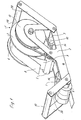
- the device 1 shown in Figures 1 to 4 is with a frame equipped in which a two-part winding spool 3 for receiving a unwinding roll 4, a winding body 5, a pressure roller 6 and two Guide rollers 7 are arranged.
- the roll 4 is made by a sealing tape Butyl and a siliconized carrier web 9 is formed, with the sealing tape on the side facing the carrier web 9 with an adhesive coating is.
- a in the illustrated embodiment tube formed with two slots or a bolt is formed after the separation of the sealing tape 8 from the carrier web 9, the carrier web 9 wound up again. To do this, it is inserted into the longitudinal slots.
- the carrier web 9 could also by spring or Clamping elements are held.
- the sealing tape 8 lies between the Pressure roller 6 and the two edges of glass panes 10, 11.
- By one Movement in the direction of arrow A becomes that of the sealing tape 8 and the carrier web 9 formed composite material is withdrawn from the roll 4.
- This will make the Winding spool 3 set in rotation, so that by a belt, shown in Embodiment a round belt, 12 of the winding body 5 in the same direction is driven so that the carrier web 9 can be wound up.
- Is to the winding body 5 is equipped with an appropriately designed groove, while the winding spool 3 has a pulley 13 on the same end face having.
- the frame 2 is designed so that the winding body 5 is only supported on the side on which the belt 12 located so that the carrier web 9 without hindrance from the opposite Side are inserted into the longitudinal slots of the winding body 5 can.
- the front guide roller 7 in the direction of movement A is below the Coil 3, in the illustrated embodiment, a little bit offset to their axis of rotation.
- the rear guide roller 7 in the direction of movement A stands at a relatively short distance from the pressure roller 6.
- the winding spool 3 is formed in two parts, the belt 12 facing flanged disc is screwed to the cylindrical core. This screw connection is released when changing the roller 4, so that the Roll can be easily pushed onto the core.
- the pressure roller 6 has on both ends a larger diameter than in the middle area, because the front ends on the Put the edges of the two glass panes 10, 11 on.
- the two guide rollers 7 on the Circumferential surface of a circumferential guide bead 14, which in a groove 15 a Intervene web 16 of the mullion or transom profile.
- the roller 4 in the Direction of movement A is in front of the pressure roller 6, so that when the Device 1, the roller 4 is set in rotation and which comes out of the sealing tape 8 and the carrier web 9 formed composite material is withdrawn therefrom. Since the Device guided straight along webs of the mullion or transom profile is, the edge strips to be glued to the glass panes 10, 11 Sealing tape 8 always constant. This is the necessary sealing effect ensured.
Landscapes
- Auxiliary Devices For And Details Of Packaging Control (AREA)
- Package Closures (AREA)
- Load-Bearing And Curtain Walls (AREA)
- Securing Of Glass Panes Or The Like (AREA)
- Adhesive Tape Dispensing Devices (AREA)
- Adhesives Or Adhesive Processes (AREA)
Description
Es zeigen:
- Figur 1
- die erfindungsgemäße handgeführte Vorrichtung einer perspektivischen Darstellung,
- Figur 2
- die Vorrichtung nach der Figur 1 in einer Seitenansicht, jedoch in entgegengesetzter Blickrichtung,
- Figur 3
- eine Teildraufsicht auf die Vorrichtung gemäß den Figuren 1 und 2 und
- Figur 4
- eine Teildraufsicht auf die Vorrichtung gemäß den Figuren 1 und 2, jedoch in einer weiteren Ausführungsform.
Claims (6)
- Handgeführte Vorrichtung (1) zum Aufkleben eines Dichtbandes (8) auf die Ränder von zwei im Abstand zueinander angeordneten Glasscheiben (10, 11) einer Pfosten und Riegel aufweisenden Fassade, wobei das Dichtband (8) eine einseitige, durch eine silikonisierte Trägerbahn (9) abgedeckte Klebebeschichtung trägt, und dieser Materialverbund mittels einer Wickelhülse (3) zu einer Rolle (4) aufgewickelt ist, und die Vorrichtung (1) eine Aufnahme für die aufzuwickelnde Rolle (4) und Führungselemente (7) zum Verschieben der Vorrichtung sowie eine Andrückrolle für das aufzuklebende Dichtband und einen rotierend antreibbaren Wickelkörper (5) für die silikonisierte Trägerbahn (9) enthält, dadurch gekennzeichnet, dass die Führungselemente aus zwei im Abstand zueinander angeordneten Führungsrollen (7) bestehen, die auf der Mantelfläche mit jeweils einer umlaufenden Führungswulst (14) versehen sind, die in einer Nut des Pfostenprofils führbar sind oder dass jede Führungsrolle (7) auf der Mantelfläche (2) im Abstand zueinander stehende Führungswülste (17, 18) aufweist, die entlang eines. Steges (16) des Pfosten- oder Riegelprofils gleiten, und dass die Aufnahme für die abzuwickelnde Rolle (4) die Führungselemente (7), die Andrückrolle (6) und der Wickelkörper (5) in einem gemeinsamen Gestell angeordnet sind.
- Handgeführte Vorrichtung nach Anspruch 1, dadurch gekennzeichnet, dass die in Bewegungsrichtung A der Vorrichtung (1) vordere Führungsrolle (7) unter der Wickelspule (3) für die Rolle (4) oder in einem kleinen Versatz zu deren Drehachse steht und dass die in Bewegungsrichtung A der Vorrichtung (1) hintere Führungsrolle (7) in einem relativ geringen Abstand zur Andrückrolle (6) steht.
- Handgeführte Vorrichtung nach Anspruch 1, dadurch gekennzeichnet, dass die Aufnahme für die abzuwickelnde Rolle (4) eine zweiteilige Wickelspule (3) ist und dass eine der seitlichen Bordscheiben der Wickelspule (3) mit dem Kern lösbar verschraubt ist.
- Handgeführte Vorrichtung nach Anspruch 3, dadurch gekennzeichnet, dass der Abstand der seitlichen Bordscheiben der Wickelspule (3) mittels Distanzringen veränderbar ist.
- Handgeführte Vorrichtung nach einem oder mehreren der vorhergehenden Ansprüche 1 bis 4, dadurch gekennzeichnet, dass das Gestell (2), bezogen auf die Bewegungsrichtung A der Vorrichtung (1) im vorderen und hinteren Bereich jeweils einen Handgriff (18, 19) trägt.
- Handgeführte Vorrichtung nach einem oder mehreren der vorhergehenden Ansprüche 1 bis 5, dadurch gekennzeichnet, dass der Wickelkörper (5) die Trägerbahn (9) ausschließlich an der einem Riemen (12) zugeordneten Seite gelagert ist und dass das Gestell (2) die gegenüberliegende Seite freigibt.
Applications Claiming Priority (2)
| Application Number | Priority Date | Filing Date | Title |
|---|---|---|---|
| DE29718886U | 1997-10-23 | ||
| DE29718886U DE29718886U1 (de) | 1997-10-23 | 1997-10-23 | Handgeführte Vorrichtung zum Aufkleben eines Dichtbandes |
Publications (3)
| Publication Number | Publication Date |
|---|---|
| EP0911290A2 EP0911290A2 (de) | 1999-04-28 |
| EP0911290A3 EP0911290A3 (de) | 1999-11-17 |
| EP0911290B1 true EP0911290B1 (de) | 2004-02-18 |
Family
ID=8047671
Family Applications (1)
| Application Number | Title | Priority Date | Filing Date |
|---|---|---|---|
| EP98118523A Expired - Lifetime EP0911290B1 (de) | 1997-10-23 | 1998-09-30 | Handgeführte Vorrichtung zum Aufkleben eines Dichtbandes |
Country Status (3)
| Country | Link |
|---|---|
| EP (1) | EP0911290B1 (de) |
| AT (1) | ATE259753T1 (de) |
| DE (2) | DE29718886U1 (de) |
Cited By (1)
| Publication number | Priority date | Publication date | Assignee | Title |
|---|---|---|---|---|
| CN108222435A (zh) * | 2017-12-30 | 2018-06-29 | 吴迪 | 一种墙面抹灰机 |
Families Citing this family (4)
| Publication number | Priority date | Publication date | Assignee | Title |
|---|---|---|---|---|
| DE102011116172A1 (de) | 2011-10-14 | 2013-04-18 | Volkswagen Aktiengesellschaft | Manuell handhabbare Anpressvorrichtung und Verfahren zum Betreiben derselben |
| US9203559B2 (en) | 2012-01-27 | 2015-12-01 | Blackberry Limited | System and method for supporting inter-band carrier aggregation with different UL/DL TDD configurations |
| CN104132039B (zh) * | 2014-06-19 | 2017-02-08 | 宁波敏实汽车零部件技术研发有限公司 | 泡棉条粘贴工具与粘贴方法 |
| CN115139262A (zh) * | 2022-06-30 | 2022-10-04 | 安徽泰乐玛科技有限公司 | 一种用于高速磁浮列车整流罩的气密封条安装辅助装置 |
Family Cites Families (2)
| Publication number | Priority date | Publication date | Assignee | Title |
|---|---|---|---|---|
| US4648935A (en) * | 1984-12-24 | 1987-03-10 | Gencorp Inc. | Tape applying apparatus |
| DE9318310U1 (de) * | 1993-12-01 | 1994-02-10 | Czepat, Hans-Jürgen, 78333 Stockach | Handgerät für Klebebänder mit Schutzfolie |
-
1997
- 1997-10-23 DE DE29718886U patent/DE29718886U1/de not_active Expired - Lifetime
-
1998
- 1998-09-30 DE DE59810781T patent/DE59810781D1/de not_active Expired - Lifetime
- 1998-09-30 AT AT98118523T patent/ATE259753T1/de not_active IP Right Cessation
- 1998-09-30 EP EP98118523A patent/EP0911290B1/de not_active Expired - Lifetime
Cited By (1)
| Publication number | Priority date | Publication date | Assignee | Title |
|---|---|---|---|---|
| CN108222435A (zh) * | 2017-12-30 | 2018-06-29 | 吴迪 | 一种墙面抹灰机 |
Also Published As
| Publication number | Publication date |
|---|---|
| EP0911290A2 (de) | 1999-04-28 |
| ATE259753T1 (de) | 2004-03-15 |
| EP0911290A3 (de) | 1999-11-17 |
| DE29718886U1 (de) | 1997-12-11 |
| DE59810781D1 (de) | 2004-03-25 |
Similar Documents
| Publication | Publication Date | Title |
|---|---|---|
| EP0692375B1 (de) | Einrichtung zur Bearbeitung von Material | |
| DE2811842C2 (de) | Abdeckmaschine | |
| EP0124828A2 (de) | Vorrichtung zur Wärmedämmung und Klimatisierung | |
| EP0868380B1 (de) | Vorrichtung zum aufbringen von klebendem montageband | |
| DE69003566T2 (de) | Maskiervorrichtung mit einem Element zum Führen des Bandes. | |
| EP0458112A1 (de) | Vorrichtung zum Verbinden von Materialbahnen | |
| DE3539586C2 (de) | ||
| DE19958274A1 (de) | Abschneider für klebende Etiketten | |
| DE69629345T2 (de) | Aufbringvorrichtung für ein flexibles Band und sein Betriebsverfahren | |
| DE102018206468B4 (de) | Klebebandversatzabroller | |
| DE2612373A1 (de) | Leiste mit metallueberzug und verfahren zu ihrer herstellung | |
| EP0911290B1 (de) | Handgeführte Vorrichtung zum Aufkleben eines Dichtbandes | |
| AT508998B1 (de) | Vorrichtung zum applizieren flexibler abstandhalterbänder | |
| DE3903599A1 (de) | Maschine zum anbringen eines klebmittels auf langgestrecktem bahnmaterial | |
| DE3320701C2 (de) | Stellvorrichtung zum Verstellen des Abstandes zwischen mehreren Bauteilen, insbesondere zwischen Schneidwerkzeugen zum Schlitzen einer Materialbahn | |
| DE2227395A1 (de) | Vorrichtung zum verlegen von dichtungsstreifen | |
| DE3115835C2 (de) | Klebewalze in einer Abwickelanlage | |
| DE2632337A1 (de) | Vorrichtung zum beschichten der seiten eines abstandshalterahmens fuer isolierglasscheiben mit einer aushaertenden klebeschicht | |
| DE2118570B2 (de) | Handvorrichtung zum aufbringen einer selbstklebenden kunststoffolie auf eine oberflaeche einer gardinenleiste | |
| DE4315261C2 (de) | Verfahren und Vorrichtung zur Herstellung eines Wabenkörpers | |
| EP0102448B1 (de) | Vorrichtung zum Einbringen eines Dichtungsstranges aus elastischem Material in eine Bauwerksfuge | |
| DE2201907A1 (de) | Vorrichtung zum schneiden bahnenfoermigen materials in laengsgerichtete streifen | |
| DE3336926A1 (de) | Geraet zum anbringen eines selbstklebenden, auf der klebseite eine abziehbare schutzfolie tragenden bandes | |
| DE3109165C2 (de) | Vorrichtung zum Einbringen eines elastischen Dichtungsstranges in eine Fuge | |
| CH536778A (de) | Vorrichtung zum Verlegen von Dichtungsstreifen |
Legal Events
| Date | Code | Title | Description |
|---|---|---|---|
| PUAI | Public reference made under article 153(3) epc to a published international application that has entered the european phase |
Free format text: ORIGINAL CODE: 0009012 |
|
| AK | Designated contracting states |
Kind code of ref document: A2 Designated state(s): AT BE CH DE FR GB LI NL |
|
| AX | Request for extension of the european patent |
Free format text: AL;LT;LV;MK;RO;SI |
|
| PUAL | Search report despatched |
Free format text: ORIGINAL CODE: 0009013 |
|
| AK | Designated contracting states |
Kind code of ref document: A3 Designated state(s): AT BE CH CY DE DK ES FI FR GB GR IE IT LI LU MC NL PT SE |
|
| AX | Request for extension of the european patent |
Free format text: AL;LT;LV;MK;RO;SI |
|
| 17P | Request for examination filed |
Effective date: 20000419 |
|
| AKX | Designation fees paid |
Free format text: AT BE CH DE FR GB LI NL |
|
| 17Q | First examination report despatched |
Effective date: 20020117 |
|
| GRAP | Despatch of communication of intention to grant a patent |
Free format text: ORIGINAL CODE: EPIDOSNIGR1 |
|
| GRAS | Grant fee paid |
Free format text: ORIGINAL CODE: EPIDOSNIGR3 |
|
| GRAA | (expected) grant |
Free format text: ORIGINAL CODE: 0009210 |
|
| AK | Designated contracting states |
Kind code of ref document: B1 Designated state(s): AT BE CH DE FR GB LI NL |
|
| REG | Reference to a national code |
Ref country code: GB Ref legal event code: FG4D Free format text: NOT ENGLISH |
|
| REG | Reference to a national code |
Ref country code: CH Ref legal event code: NV Representative=s name: ISLER & PEDRAZZINI AG Ref country code: CH Ref legal event code: EP |
|
| REF | Corresponds to: |
Ref document number: 59810781 Country of ref document: DE Date of ref document: 20040325 Kind code of ref document: P |
|
| GBT | Gb: translation of ep patent filed (gb section 77(6)(a)/1977) |
Effective date: 20040315 |
|
| ET | Fr: translation filed | ||
| PLBE | No opposition filed within time limit |
Free format text: ORIGINAL CODE: 0009261 |
|
| STAA | Information on the status of an ep patent application or granted ep patent |
Free format text: STATUS: NO OPPOSITION FILED WITHIN TIME LIMIT |
|
| 26N | No opposition filed |
Effective date: 20041119 |
|
| REG | Reference to a national code |
Ref country code: CH Ref legal event code: PCAR Free format text: ISLER & PEDRAZZINI AG;POSTFACH 1772;8027 ZUERICH (CH) |
|
| PGFP | Annual fee paid to national office [announced via postgrant information from national office to epo] |
Ref country code: NL Payment date: 20090921 Year of fee payment: 12 Ref country code: GB Payment date: 20090922 Year of fee payment: 12 Ref country code: CH Payment date: 20090923 Year of fee payment: 12 Ref country code: AT Payment date: 20090921 Year of fee payment: 12 |
|
| PGFP | Annual fee paid to national office [announced via postgrant information from national office to epo] |
Ref country code: BE Payment date: 20090922 Year of fee payment: 12 |
|
| PGFP | Annual fee paid to national office [announced via postgrant information from national office to epo] |
Ref country code: DE Payment date: 20101013 Year of fee payment: 13 |
|
| BERE | Be: lapsed |
Owner name: *SCHUCO INTERNATIONAL K.G. Effective date: 20100930 |
|
| REG | Reference to a national code |
Ref country code: NL Ref legal event code: V1 Effective date: 20110401 |
|
| REG | Reference to a national code |
Ref country code: CH Ref legal event code: PL |
|
| GBPC | Gb: european patent ceased through non-payment of renewal fee |
Effective date: 20100930 |
|
| REG | Reference to a national code |
Ref country code: FR Ref legal event code: ST Effective date: 20110531 |
|
| PG25 | Lapsed in a contracting state [announced via postgrant information from national office to epo] |
Ref country code: BE Free format text: LAPSE BECAUSE OF NON-PAYMENT OF DUE FEES Effective date: 20100930 Ref country code: FR Free format text: LAPSE BECAUSE OF NON-PAYMENT OF DUE FEES Effective date: 20100930 Ref country code: CH Free format text: LAPSE BECAUSE OF NON-PAYMENT OF DUE FEES Effective date: 20100930 Ref country code: LI Free format text: LAPSE BECAUSE OF NON-PAYMENT OF DUE FEES Effective date: 20100930 |
|
| PG25 | Lapsed in a contracting state [announced via postgrant information from national office to epo] |
Ref country code: NL Free format text: LAPSE BECAUSE OF NON-PAYMENT OF DUE FEES Effective date: 20110401 Ref country code: GB Free format text: LAPSE BECAUSE OF NON-PAYMENT OF DUE FEES Effective date: 20100930 Ref country code: AT Free format text: LAPSE BECAUSE OF NON-PAYMENT OF DUE FEES Effective date: 20100930 |
|
| PGFP | Annual fee paid to national office [announced via postgrant information from national office to epo] |
Ref country code: FR Payment date: 20091005 Year of fee payment: 12 |
|
| REG | Reference to a national code |
Ref country code: DE Ref legal event code: R119 Ref document number: 59810781 Country of ref document: DE Effective date: 20120403 |
|
| PG25 | Lapsed in a contracting state [announced via postgrant information from national office to epo] |
Ref country code: DE Free format text: LAPSE BECAUSE OF NON-PAYMENT OF DUE FEES Effective date: 20120403 |