EP0911554B1 - Joint combiné à brosses/labyrinthe pour machines rotatives - Google Patents
Joint combiné à brosses/labyrinthe pour machines rotatives Download PDFInfo
- Publication number
- EP0911554B1 EP0911554B1 EP98308700A EP98308700A EP0911554B1 EP 0911554 B1 EP0911554 B1 EP 0911554B1 EP 98308700 A EP98308700 A EP 98308700A EP 98308700 A EP98308700 A EP 98308700A EP 0911554 B1 EP0911554 B1 EP 0911554B1
- Authority
- EP
- European Patent Office
- Prior art keywords
- labyrinth
- seal
- bristles
- brush seal
- segment
- Prior art date
- Legal status (The legal status is an assumption and is not a legal conclusion. Google has not performed a legal analysis and makes no representation as to the accuracy of the status listed.)
- Expired - Lifetime
Links
- 239000010935 stainless steel Substances 0.000 claims description 3
- 229910001220 stainless steel Inorganic materials 0.000 claims description 3
- 238000011144 upstream manufacturing Methods 0.000 claims 1
- 239000012530 fluid Substances 0.000 description 4
- 239000000835 fiber Substances 0.000 description 3
- 238000007789 sealing Methods 0.000 description 3
- 230000004888 barrier function Effects 0.000 description 2
- 235000001674 Agaricus brunnescens Nutrition 0.000 description 1
- 229910000831 Steel Inorganic materials 0.000 description 1
- WAIPAZQMEIHHTJ-UHFFFAOYSA-N [Cr].[Co] Chemical compound [Cr].[Co] WAIPAZQMEIHHTJ-UHFFFAOYSA-N 0.000 description 1
- 229910045601 alloy Inorganic materials 0.000 description 1
- 239000000956 alloy Substances 0.000 description 1
- 230000008901 benefit Effects 0.000 description 1
- 230000008859 change Effects 0.000 description 1
- 230000001419 dependent effect Effects 0.000 description 1
- 230000000694 effects Effects 0.000 description 1
- 238000003780 insertion Methods 0.000 description 1
- 230000037431 insertion Effects 0.000 description 1
- 238000004519 manufacturing process Methods 0.000 description 1
- 239000000463 material Substances 0.000 description 1
- 239000002184 metal Substances 0.000 description 1
- 230000005012 migration Effects 0.000 description 1
- 238000013508 migration Methods 0.000 description 1
- 238000012986 modification Methods 0.000 description 1
- 230000004048 modification Effects 0.000 description 1
- 238000010248 power generation Methods 0.000 description 1
- 239000010959 steel Substances 0.000 description 1
- 230000002459 sustained effect Effects 0.000 description 1
- 230000001052 transient effect Effects 0.000 description 1
Images


Classifications
-
- F—MECHANICAL ENGINEERING; LIGHTING; HEATING; WEAPONS; BLASTING
- F16—ENGINEERING ELEMENTS AND UNITS; GENERAL MEASURES FOR PRODUCING AND MAINTAINING EFFECTIVE FUNCTIONING OF MACHINES OR INSTALLATIONS; THERMAL INSULATION IN GENERAL
- F16J—PISTONS; CYLINDERS; SEALINGS
- F16J15/00—Sealings
- F16J15/44—Free-space packings
- F16J15/447—Labyrinth packings
-
- F—MECHANICAL ENGINEERING; LIGHTING; HEATING; WEAPONS; BLASTING
- F16—ENGINEERING ELEMENTS AND UNITS; GENERAL MEASURES FOR PRODUCING AND MAINTAINING EFFECTIVE FUNCTIONING OF MACHINES OR INSTALLATIONS; THERMAL INSULATION IN GENERAL
- F16J—PISTONS; CYLINDERS; SEALINGS
- F16J15/00—Sealings
- F16J15/44—Free-space packings
- F16J15/441—Free-space packings with floating ring
- F16J15/442—Free-space packings with floating ring segmented
-
- F—MECHANICAL ENGINEERING; LIGHTING; HEATING; WEAPONS; BLASTING
- F16—ENGINEERING ELEMENTS AND UNITS; GENERAL MEASURES FOR PRODUCING AND MAINTAINING EFFECTIVE FUNCTIONING OF MACHINES OR INSTALLATIONS; THERMAL INSULATION IN GENERAL
- F16J—PISTONS; CYLINDERS; SEALINGS
- F16J15/00—Sealings
- F16J15/16—Sealings between relatively-moving surfaces
- F16J15/32—Sealings between relatively-moving surfaces with elastic sealings, e.g. O-rings
- F16J15/3284—Sealings between relatively-moving surfaces with elastic sealings, e.g. O-rings characterised by their structure; Selection of materials
- F16J15/3288—Filamentary structures, e.g. brush seals
-
- Y—GENERAL TAGGING OF NEW TECHNOLOGICAL DEVELOPMENTS; GENERAL TAGGING OF CROSS-SECTIONAL TECHNOLOGIES SPANNING OVER SEVERAL SECTIONS OF THE IPC; TECHNICAL SUBJECTS COVERED BY FORMER USPC CROSS-REFERENCE ART COLLECTIONS [XRACs] AND DIGESTS
- Y10—TECHNICAL SUBJECTS COVERED BY FORMER USPC
- Y10S—TECHNICAL SUBJECTS COVERED BY FORMER USPC CROSS-REFERENCE ART COLLECTIONS [XRACs] AND DIGESTS
- Y10S277/00—Seal for a joint or juncture
- Y10S277/908—Seal for use in rotating and reciprocating arrangement
-
- Y—GENERAL TAGGING OF NEW TECHNOLOGICAL DEVELOPMENTS; GENERAL TAGGING OF CROSS-SECTIONAL TECHNOLOGIES SPANNING OVER SEVERAL SECTIONS OF THE IPC; TECHNICAL SUBJECTS COVERED BY FORMER USPC CROSS-REFERENCE ART COLLECTIONS [XRACs] AND DIGESTS
- Y10—TECHNICAL SUBJECTS COVERED BY FORMER USPC
- Y10S—TECHNICAL SUBJECTS COVERED BY FORMER USPC CROSS-REFERENCE ART COLLECTIONS [XRACs] AND DIGESTS
- Y10S277/00—Seal for a joint or juncture
- Y10S277/935—Seal made of a particular material
Definitions
- This invention relates to turbo machinery in general and more specifically, to combined labyrinth/brush seals for steam and gas turbines.
- Rotary machines such as steam and gas turbines, used for power generation and mechanical drive applications are generally large machines consisting of multiple turbine stages. High pressure fluid flowing through the turbine stages must pass through a series of stationary and rotating components, and seals between the stationary and rotating components are used to control leakage. The efficiency of the turbine is directly dependent on the ability of the seals to prevent leakage, e.g., between the rotor and stator.
- Turbine designs are conventionally classified as either an impulse (with the majority of the pressure drop occurring across fixed nozzles) or a reaction (with the pressure drop more evenly distributed between the rotating and stationary vanes) type. Both designs employ sharp, rigid teeth, known as labyrinth seals to control leakage. Traditionally, labyrinth seals of either a hi-lo (alternating teeth height) or straight shaft design are used. Such seals are employed at virtually all turbine locations where leakage between rotating and stationary components must be controlled.
- Brush seals are generally less prone to leakage than labyrinth seals.
- a brush seal can also accommodate relative radial movement between fixed and rotational components, for example, between a rotor and a stator, because of the flexure of the seal bristles.
- Brush seals also generally conform better to surface nonuniformities. The result of using brush seals is better sustained rotary machine performance than is generally possible with labyrinth seals.
- EP-A-0 816 725 and EP-A-0 816 726 are family members of these applications.
- Brush seals disclosed in the '665 and '667 applications comprise bristle packs secured between a pair of rigid plates, with the bristles welded to the plates.
- the plates are precisely machined to fit within a stationary annular groove (the brush seals typically include four segments which, when installed, create a 360° seal).
- individual brush seals are designed for one particular diameter groove.
- several different diameter seals may be required which nevertheless perform substantially identical functions. Accordingly, different tooling is required for each small diameter change, significantly increasing the cost of such seals.
- a labyrinth/brush seal combination is also known from US-A-5 630 590.
- a labyrinth/brush seal combination for a rotating machine comprising an arcuate segment of predetermined axial extent carrying a plurality of axially spaced, circumferentially and radially extending seal teeth, and at least one circumferentially extending array of discrete bristles carried by said segment at a predetermined axial location therealong and projecting beyond the radial extent of said teeth, said bristles held within a first flexible carrier strip slidably and removably received within a slot in said segment.
- a rotary machine comprising: rotatable component; a fixed component surrounding said rotatable component; said components lying about a common axis; a labyrinth seal between said fixed and rotatable components comprising a plurality of seal segments, each segment including a plurality of axially spaced circumferentially extending teeth projecting radially toward said rotatable component; each labyrinth seal segment including at least one brush seal comprising an array of discrete bristles carried by said fixed component for disposition axially adjacent at least one of said teeth; wherein said discrete bristles are mounted to a first elongated, flexible, deformable carrier strip and wherein said strip is slidably received within an arcuate slot formed in said segment whereby said brush seal conforms to the curvature of said segment.
- unique brush seal segments are provided which have great flexibility with respect to seal diameter and which significantly reduce the cost of the seals.
- brush bristles are mounted in a flexible holder in the form of an elongated, stainless steel channel which is crimped to the bristles.
- This arrangement allows simple and cost effective manufacture of essentially continuous lengths of the bristle portion of the brush seal, regardless of the ultimate diameter of the seal.
- the brush portion cut into appropriate segment lengths, is then slidably installed within T-shaped slots machined, for example, in labyrinth seal segments, adjacent one of the rigid labyrinth teeth which supports the bristles.
- the T-shaped slots are machined to the required diameter, and the separately manufactured brush portion can be cut to the segment lengths and pushed into the slots, with the flexible channel conforming to the curvature of the slot.
- the brush portions with flexible holder may be secured within respective segment slots by set screws or other suitable means.
- the significant advantage of this invention is that the brush arrangement including the flexible top component can be manufactured separately in a cost-effective manner, and then installed within various diameter T-slots cut into the labyrinth segments, stator, or other stationary machine components.
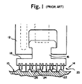
- a labyrinth seal located between the rotating shaft 10 and the stationary housing 12, includes a seal ring 16 disposed about shaft 10 separating high and low pressure regions on axially opposite sides of the ring. It will be appreciated that while only one seal 16 is disclosed, typically multiple-stage labyrinth seals are provided about rotor shafts.
- Each seal ring 16 is formed of an annular array (usually four or more) arcuate seal elements 18 having sealing faces 20 and a plurality of radially projecting, axially spaced teeth 22.
- the teeth as shown are of a hi-lo design for obtaining close clearances with the radial projections or ribs 24 and the grooves 26 of the shaft 10.
- the labyrinth seal functions by placing a relatively large number of barriers, i.e., the teeth, to the flow of fluid from a high pressure region to a low pressure region on opposite sides of the seal, with each barrier forcing the fluid to follow a tortuous path whereby pressure drop is created.
- the sum of the pressure drops across the labyrinth seal is by definition the pressure difference between the high and low pressure regions on axially opposite sides thereof.
- These labyrinth seal ring segments are typically spring-backed and are thus free to move radially when subjected to severe rotor/seal interference.
- the springs maintain the seal ring segments 16 radially outwardly away from the rotor, for example, during startup and shutdown, with fluid pressure being supplied between the seal ring segments and the rotor housing to displace the seal ring segments radially inwardly to obtain a less clearance with the rotor, i.e., close the seals, after the rotor has been brought up to speed.
- FIG. 2 and 2A there is illustrated in accordance with this invention an example of a combined labyrinth/brush seal 28 incorporated as a retrofit or as original equipment in a labyrinth seal.
- a T-shaped groove 30 is formed in the labyrinth seal segment 32, with the stem of the groove located adjacent the centrally located rigid tooth 34.
- the rigid labyrinth tooth 34 lies on the downstream side of the brush seal segment 32 to support the brush bristles 38 in the axial direction.
- the bristles 38 (best seen in Figures 3 and 5) of this new seal are comprised of conventional brush seal material, e.g., wires of Haynes 25 stainless steel. Other alloys may be appropriate, however, for specific applications.
- the stiff wire bristles are arranged in two or more layers, and canted at a 45° angle, as best seen in Figures 2, 3 and 6. Along the fold line, the bristles are held together by woven fibers 40, such that the bristles may be folded over a thin (e.g., 10 mils), flexible metal strip or shim 42 best seen in Figure 4, with the woven fibers 40 extending along the top of the shim 42.
- the brush seal per se can be manufactured in essentially endless or continuous form, independent of any diameter groove in which it may be placed.
- an appropriate length segment is cut from the supply and is pushed into the precisely machined T-slot 30 in a labyrinth seal segment 32. As the segment is pushed into the slot, the flexible seal element easily conforms to the diameter of the slot.
- set screws one shown at 46 or other suitable means may be employed to lock the brush component radially in place within the slot 30. The set screw also prevents any circumferential migration of the brush component within the slot.
- next adjacent labyrinth tooth 34 on the low pressure side of the brush seal provides lateral support for the bristles 38 as described above.
- a blank triangular area 39 appears at the end of each segment. Tooth 34 nevertheless continues to effect a degree of sealing at this location.
- the length of the bristles 38 need not be cut to precise tolerances since they will essentially wear quickly to the required length if initially cut to a slightly greater length than required (see Figure 2A), as a result of contact with the rotor.
- the seal element By so constructing the seal element, the cost has been significantly reduced, particularly because the seal is adaptable to any diameter and little is required in terms of close tolerances.
- the location of the brush component in the labyrinth seal may be varied, and that the number of brush components within the seal may be varied as well.
Landscapes
- Engineering & Computer Science (AREA)
- General Engineering & Computer Science (AREA)
- Mechanical Engineering (AREA)
- Turbine Rotor Nozzle Sealing (AREA)
- Sealing Using Fluids, Sealing Without Contact, And Removal Of Oil (AREA)
- Sealing Devices (AREA)
Claims (10)
- Joint combiné à labyrinthe/brosse pour machine rotative comprenant un segment courbé (32) de dimension axiale déterminée portant une pluralité de dents d'étanchéité axialement espacées et s'étendant circonférentiellement et radialement (34), et au moins un réseau, s'étendant circonférentiellement, de poils discrets (38) portés par ledit segment en une position axiale déterminée le long de celui-ci et faisant saillie au-delà de l'étendue radiale desdites dents, lesdits poils étant maintenus à l'intérieur d'une première bande de support souple (44) logée de manière coulissante et amovible dans une fente (30) prévue dans ledit segment.
- Joint combiné à labyrinthe/brosse selon la revendication 1, dans lequel lesdits poils sont pliés autour d'une autre bande de support souple (42) et tenus en place par ladite première bande souple (44) qui est pincée autour de ladite autre bande de support souple.
- Joint combiné à labyrinthe/brosse selon la revendication 1 ou 2, dans lequel lesdits poils (38) sont tissés ensemble autour d'une ligne de pliage.
- Joint combiné à labyrinthe/brosse selon la revendication 1, 2 ou 3, dans lequel lesdits poils (38) sont orientés selon un angle d'environ 45° par rapport à la verticale.
- Joint combiné à labyrinthe/brosse selon l'une quelconque des revendications précédentes, dans lequel ledit réseau de poils discrets se trouve en position adjacente rapprochée de ladite pluralité de dents d'étanchéité axialement espacées et s'étendant circonférentiellement et radialement (34), d'un côté amont de celles-ci.
- Joint combiné à labyrinthe/brosse selon l'une quelconque des revendications précédentes, dans lequel ladite fente (30) est sensiblement en forme de T, et comprend une tige et une section transversale, ladite bande de support souple se trouvant dans ladite section transversale.
- Machine rotative comprenant :un organe rotatif (10) ;un organe fixe (12) entourant ledit organe rotatif ;lesdits organes se trouvant autour d'un axe commun ;un joint à labyrinthe entre lesdits organes fixe et rotatif comprenant une pluralité de segments de joint (32), chaque segment comprenant une pluralité de dents axialement espacées s'étendant circonférentiellement (34), faisant saillie radialement vers ledit organe rotatif ;chaque segment de joint à labyrinthe comportant au moins un joint à brosse comprenant un réseau de poils discrets (38) portés par ledit organe fixe en vue d'une disposition axialement adjacente à au moins l'une (34) desdites dents, lesdits poils discrets étant montés sur une première bande de support allongée, souple et déformable (44) et ladite bande étant reçue de manière coulissante dans une fente courbée (30) formée dans ledit segment, grâce à quoi ledit joint à brosse se conforme à la courbure dudit segment.
- Machine rotative selon la revendication 7, dans laquelle ledit au moins un joint à brosse se trouve à peu près à mi-chemin le long d'une étendue axiale desdits segments, et dans laquelle une dent de labyrinthe adjacente (34) constitue un support latéral pour ledit au moins un joint à brosse.
- Machine rotative selon la revendication 8, dans laquelle ladite bande de support (44) comprend de l'acier inoxydable.
- Machine rotative selon la revendication 7 ou 8, dans laquelle lesdits poils sont pliés autour de ladite première bande de support souple (42) et tenus en place par une seconde bande souple (44) qui est pincée autour de ladite autre bande de support souple.
Applications Claiming Priority (2)
| Application Number | Priority Date | Filing Date | Title |
|---|---|---|---|
| US08/956,686 US6027121A (en) | 1997-10-23 | 1997-10-23 | Combined brush/labyrinth seal for rotary machines |
| US956686 | 1997-10-23 |
Publications (2)
| Publication Number | Publication Date |
|---|---|
| EP0911554A1 EP0911554A1 (fr) | 1999-04-28 |
| EP0911554B1 true EP0911554B1 (fr) | 2004-01-07 |
Family
ID=25498551
Family Applications (1)
| Application Number | Title | Priority Date | Filing Date |
|---|---|---|---|
| EP98308700A Expired - Lifetime EP0911554B1 (fr) | 1997-10-23 | 1998-10-23 | Joint combiné à brosses/labyrinthe pour machines rotatives |
Country Status (6)
| Country | Link |
|---|---|
| US (1) | US6027121A (fr) |
| EP (1) | EP0911554B1 (fr) |
| JP (1) | JPH11201293A (fr) |
| KR (1) | KR100503999B1 (fr) |
| DE (1) | DE69820960T2 (fr) |
| TW (1) | TW384353B (fr) |
Families Citing this family (71)
| Publication number | Priority date | Publication date | Assignee | Title |
|---|---|---|---|---|
| US6318728B1 (en) * | 1997-07-11 | 2001-11-20 | Demag Delaval Turbomachinery Corporation | Brush-seal designs for elastic fluid turbines |
| US6257588B1 (en) * | 1998-09-22 | 2001-07-10 | General Electric Company | Brush seal and rotary machine including such brush seal |
| US6030175A (en) * | 1998-09-23 | 2000-02-29 | General Electric Company | Hybrid seal and rotary machine containing such hybrid seal |
| US6250641B1 (en) * | 1998-11-25 | 2001-06-26 | General Electric Co. | Positive biased packing ring brush seal combination |
| US6139019A (en) * | 1999-03-24 | 2000-10-31 | General Electric Company | Seal assembly and rotary machine containing such seal |
| US6286211B1 (en) * | 1999-03-24 | 2001-09-11 | General Electric Company | Method for making a brush-tooth seal |
| US7032903B1 (en) * | 1999-04-06 | 2006-04-25 | Turbocare, Inc. | Brush-seal designs for turbines and similar rotary apparatus |
| US6261057B1 (en) * | 1999-10-04 | 2001-07-17 | General Electric Company | Arrangement and method for accurately radially locating a turbine brush seal |
| US6308958B1 (en) * | 1999-10-12 | 2001-10-30 | General Electric Company | Arrangement and method for radially positioning a turbine brush seal |
| EP1169586B1 (fr) * | 2000-01-31 | 2007-02-21 | General Electric Company | Joints en brosses pour turbine a vapeur |
| US6422815B1 (en) | 2000-03-02 | 2002-07-23 | General Electric Company | Turbine air seal replacement rings |
| DE10011063A1 (de) * | 2000-03-07 | 2001-09-27 | Daimler Chrysler Ag | Labyrinthdichtung zwischen drehbaren Bauteilen |
| DE60142651D1 (de) * | 2000-04-06 | 2010-09-02 | Turbocare Inc | Verbesserte Bürstendichtungsentwürfe für Turbinen und ähnliche Rotationsgeräte |
| DE10018273B4 (de) * | 2000-04-13 | 2005-10-20 | Mtu Aero Engines Gmbh | Bürstendichtung |
| US6913265B2 (en) * | 2000-08-09 | 2005-07-05 | Advanced Components & Materials, Inc. | Brush seal assembly, method of manufacture and use |
| KR20020016097A (ko) * | 2000-08-24 | 2002-03-04 | 이중구 | 회전축의 밀봉조립체 |
| US6390476B1 (en) * | 2000-09-08 | 2002-05-21 | General Electric Company | Heat-resistant magnetic silicone rubber brush seals in turbomachinery and methods of application |
| WO2002023069A2 (fr) * | 2000-09-14 | 2002-03-21 | Turbocare, Inc. | Joint a brosse toroidale eventuellement placee dans une presse-garniture a labyrinthe |
| US6464230B1 (en) | 2000-10-19 | 2002-10-15 | General Electric Company | Flexible magnetic rubber brush seal for generators |
| US6880829B1 (en) * | 2000-11-06 | 2005-04-19 | Advanced Components & Materials, Inc. | Compliant brush shroud assembly for gas turbine engine compressors |
| WO2002036950A2 (fr) | 2000-11-06 | 2002-05-10 | Advanced Components And Materials, Inc. | Ensemble balai-écran compliant pour compresseurs de turbomachine à gaz |
| IT1319552B1 (it) * | 2000-12-15 | 2003-10-20 | Nuovo Pignone Spa | Sistema per adduzione di aria di raffreddamento in una turbina a gas |
| US7578509B2 (en) | 2001-02-23 | 2009-08-25 | Cmg Tech, Llc | Seal assembly and rotary machine containing such seal |
| US6644667B2 (en) | 2001-02-23 | 2003-11-11 | Cmg Tech, Llc | Seal assembly and rotary machine containing such seal |
| US20100007093A1 (en) * | 2001-02-23 | 2010-01-14 | Grondahl Clayton M | Seal Assembly and Rotary Machine Containing Such Seal |
| US6547522B2 (en) | 2001-06-18 | 2003-04-15 | General Electric Company | Spring-backed abradable seal for turbomachinery |
| US6550777B2 (en) | 2001-06-19 | 2003-04-22 | General Electric Company | Split packing ring segment for a brush seal insert in a rotary machine |
| US6402157B1 (en) * | 2001-08-20 | 2002-06-11 | General Electric Company | Brush seal and method of using brush seal |
| JP3702212B2 (ja) * | 2001-09-28 | 2005-10-05 | 三菱重工業株式会社 | 軸シール機構及びタービン |
| US6786487B2 (en) * | 2001-12-05 | 2004-09-07 | General Electric Company | Actuated brush seal |
| US7931276B2 (en) * | 2002-03-20 | 2011-04-26 | United Technologies Corporation | Brush seal |
| US6722850B2 (en) | 2002-07-22 | 2004-04-20 | General Electric Company | Endface gap sealing of steam turbine packing seal segments and retrofitting thereof |
| US6722846B2 (en) * | 2002-07-30 | 2004-04-20 | General Electric Company | Endface gap sealing of steam turbine bucket tip static seal segments and retrofitting thereof |
| US20040046327A1 (en) * | 2002-09-05 | 2004-03-11 | Menendez Robert P. | Labyrinth/brush seal combination |
| US6779799B2 (en) | 2002-11-27 | 2004-08-24 | General Electric Company | Sealing apparatus for electrical generator ventilation system |
| US6969231B2 (en) * | 2002-12-31 | 2005-11-29 | General Electric Company | Rotary machine sealing assembly |
| US20050073106A1 (en) * | 2003-10-03 | 2005-04-07 | General Electric Company | Brush seal support for turbine applications |
| DE10351583B4 (de) * | 2003-11-05 | 2020-10-22 | MTU Aero Engines AG | Dichtungsanordnung |
| US20060088409A1 (en) * | 2004-10-21 | 2006-04-27 | General Electric Company | Grouped reaction nozzle tip shrouds with integrated seals |
| US7604241B2 (en) * | 2005-09-22 | 2009-10-20 | General Electric Company | Seals for turbines and turbo machinery |
| US7255352B2 (en) * | 2005-09-29 | 2007-08-14 | General Electric Company | Pressure balanced brush seal |
| US7653993B2 (en) * | 2005-09-29 | 2010-02-02 | General Electric Company | Method of manufacturing a brush seal for sealing between stationary and rotary components |
| US7565729B2 (en) * | 2006-03-17 | 2009-07-28 | General Electric Company | Methods of manufacturing a segmented brush seal for sealing between stationary and rotary components |
| US7419164B2 (en) * | 2006-08-15 | 2008-09-02 | General Electric Company | Compliant plate seals for turbomachinery |
| US7703774B2 (en) * | 2006-09-12 | 2010-04-27 | General Electric Company | Shaft seal using shingle members |
| GB0619488D0 (en) | 2006-10-03 | 2006-11-08 | Cross Mfg 1938 Company Ltd | Brush seal assembly |
| US20080107525A1 (en) * | 2006-11-02 | 2008-05-08 | General Electric Company | Shaft seal formed of tapered compliant plate members |
| DE102007032889A1 (de) * | 2007-07-14 | 2009-01-15 | Mtu Aero Engines Gmbh | Dichtungsvorrichtung für eine Kühlmittelzufuhr an einer rotierenden Spindel sowie Werkkzeugmaschine mit einer derartigen Dichtungsvorrichtung |
| EP2039886B1 (fr) * | 2007-09-24 | 2010-06-23 | ALSTOM Technology Ltd | Soupape de retenue composite |
| US7909335B2 (en) * | 2008-02-04 | 2011-03-22 | General Electric Company | Retractable compliant plate seals |
| US8414254B2 (en) * | 2008-02-18 | 2013-04-09 | United Technologies Corporation | Sealing assembly for a turbine engine |
| US20100143102A1 (en) * | 2008-02-18 | 2010-06-10 | General Electric Company | Compliant plate seal with self-correcting behavior |
| US20090302543A1 (en) * | 2008-06-09 | 2009-12-10 | General Electric Company | Sealing systems for rotary machines and methods for modification |
| DE102008050230B4 (de) * | 2008-10-02 | 2019-06-13 | Battenfeld-Cincinnati Germany Gmbh | Vorrichtung zum Abdichten |
| US8596973B2 (en) * | 2009-12-07 | 2013-12-03 | Cmg Tech, Llc | Leaf seal assembly including polymer member and rotary machine containing such seal assembly |
| FR2957976B1 (fr) * | 2010-03-26 | 2013-04-12 | Snecma | Dispositif d'etancheite pour une enceinte d'huile d'un turboreacteur |
| GB2480680B (en) * | 2010-05-28 | 2012-10-03 | Alstom Technology Ltd | Labyrinth seal |
| FR2967748B1 (fr) * | 2010-11-24 | 2013-09-20 | Snecma | Systeme d'etancheite a joint annulaire a brosse |
| DE102010055435B4 (de) | 2010-12-21 | 2018-03-29 | Rolls-Royce Deutschland Ltd & Co Kg | Innendeckband einer Gasturbine sowie Verfahren zur Herstellung eines Innendeckbandes |
| US8872055B2 (en) * | 2011-04-12 | 2014-10-28 | Fastrax Industries, Inc. | Non-contact rail heater with insulating skirt |
| US20130022459A1 (en) * | 2011-07-18 | 2013-01-24 | General Electric Company | Seals for reducing leakage in rotary machines |
| US8657296B1 (en) * | 2011-10-26 | 2014-02-25 | Engineered Seal Products, Inc. | Radial shaft seal |
| US9394801B2 (en) | 2013-10-07 | 2016-07-19 | General Electric Company | Adjustable turbine seal and method of assembling same |
| JP6008452B2 (ja) * | 2014-03-04 | 2016-10-19 | 富士フイルム株式会社 | ラビリンスシール、流延装置、溶液製膜設備及び方法 |
| US9963991B2 (en) * | 2014-10-01 | 2018-05-08 | United Technologies Corporation | Brush seal plate |
| US10557359B2 (en) * | 2016-11-03 | 2020-02-11 | United Technologies Corporation | Seal assembly |
| CN107355540B (zh) * | 2017-08-18 | 2023-07-14 | 国网湖南省电力公司 | 间隙自适应调整密封结构 |
| TWI671480B (zh) * | 2017-10-03 | 2019-09-11 | 上銀科技股份有限公司 | 具有防塵蓋之滾珠螺帽 |
| US10598038B2 (en) | 2017-11-21 | 2020-03-24 | Honeywell International Inc. | Labyrinth seal with variable tooth heights |
| US12336927B2 (en) | 2020-02-19 | 2025-06-24 | Convatec Limited | Outlet valve for an ostomy appliance |
| WO2025069703A1 (fr) * | 2023-09-29 | 2025-04-03 | 三菱重工業株式会社 | Machine tournante |
Family Cites Families (83)
| Publication number | Priority date | Publication date | Assignee | Title |
|---|---|---|---|---|
| US768593A (en) * | 1903-03-24 | 1904-08-30 | Gen Electric | Turbine-generator. |
| US779785A (en) * | 1903-12-24 | 1905-01-10 | Gen Electric | Packing for elastic-fluid turbines. |
| US910472A (en) * | 1907-06-24 | 1909-01-19 | Gen Electric | Elastic-fluid turbine. |
| US957887A (en) * | 1908-09-28 | 1910-05-17 | Gen Electric | Packing for elastic-fluid-turbine shafts. |
| US980282A (en) * | 1909-07-26 | 1911-01-03 | Gen Electric | Leakage-reducing device for steam-turbines. |
| US1352277A (en) * | 1919-01-09 | 1920-09-07 | Gen Electric | Elastic-fluid turbine |
| US1352278A (en) * | 1920-03-03 | 1920-09-07 | Gen Electric | Elastic-fluid turbine |
| US1505647A (en) * | 1920-11-05 | 1924-08-19 | Gen Electric | Packing for elastic-fluid turbines and the like |
| US1594838A (en) * | 1921-08-29 | 1926-08-03 | Kegresse Adolphe | Dust cap |
| US1505924A (en) * | 1922-05-19 | 1924-08-19 | Gen Electric | Shaft packing for elastic-fluid turbines and the like |
| US1536014A (en) * | 1923-03-23 | 1925-04-28 | Gen Electric | Packing for elastic-fluid turbines and the like |
| US1651855A (en) * | 1924-06-24 | 1927-12-06 | Gen Electric | Elastic-fluid turbine |
| US1670071A (en) * | 1924-09-29 | 1928-05-15 | Gen Electric | Shaft packing |
| US1895930A (en) * | 1931-08-27 | 1933-01-31 | Gen Electric | Shaft packing |
| US2336323A (en) * | 1942-03-12 | 1943-12-07 | Gen Electric | Sealing arrangement for elastic fluid turbines and the like |
| US2600991A (en) * | 1949-06-14 | 1952-06-17 | Gen Electric | Labyrinth seal arrangement |
| US2709338A (en) * | 1953-01-16 | 1955-05-31 | Rolls Royce | Double-walled ducting for conveying hot gas with means to interconnect the walls |
| GB1010338A (en) * | 1962-09-11 | 1965-11-17 | Lucas Industries Ltd | Means for supporting the downstream end of a combustion chamber in a gas turbine engine |
| GB1103479A (en) * | 1966-11-24 | 1968-02-14 | Rolls Royce | Fluid seal device |
| US3759038A (en) * | 1971-12-09 | 1973-09-18 | Westinghouse Electric Corp | Self aligning combustor and transition structure for a gas turbine |
| GB1541001A (en) * | 1976-06-08 | 1979-02-21 | Schlegel Uk Ltd | Seals |
| US4195476A (en) * | 1978-04-27 | 1980-04-01 | General Motors Corporation | Combustor construction |
| US4202554A (en) * | 1978-05-17 | 1980-05-13 | Rolls-Royce Limited | Brush seals |
| SE7810426L (sv) * | 1978-10-05 | 1980-04-06 | Skf Ab | Tetning |
| DE2938484C2 (de) * | 1979-09-22 | 1982-06-16 | Fa. Carl Freudenberg, 6940 Weinheim | Dichtring |
| GB2070700B (en) * | 1980-03-01 | 1983-10-05 | Rolls Royce | Gas turbine seals |
| GB2076935B (en) * | 1980-05-31 | 1984-07-25 | Rolls Royce | Seals |
| US4422288A (en) * | 1981-03-02 | 1983-12-27 | General Electric Company | Aft mounting system for combustion transition duct members |
| GB2254378B (en) * | 1981-12-30 | 1993-03-31 | Rolls Royce | Gas turbine engine ring shroud ring mounting |
| DE3215334C1 (de) * | 1982-04-24 | 1983-06-09 | Dr. Johannes Heidenhain Gmbh, 8225 Traunreut | Gekapselte Messeinrichtung |
| ZA834537B (en) * | 1982-06-30 | 1984-06-27 | Skf Uk Ltd | Seals for bearings |
| US4567730A (en) * | 1983-10-03 | 1986-02-04 | General Electric Company | Shielded combustor |
| DE3514382C1 (de) * | 1985-04-20 | 1986-06-12 | Motoren Turbinen Union | Buerstendichtung |
| DE3606283A1 (de) * | 1985-07-31 | 1987-02-12 | Mtu Muenchen Gmbh | Buerstendichtung |
| DE3606284A1 (de) * | 1985-07-31 | 1987-02-12 | Mtu Muenchen Gmbh | Verfahren zur herstellung einer buerstendichtung und vorrichtung zur durchfuehrung des verfahrens |
| GB2191825B (en) * | 1986-06-18 | 1989-12-13 | Rolls Royce Plc | Means for retaining a brush seal in a housing |
| GB2198195B (en) * | 1986-12-06 | 1990-05-16 | Rolls Royce Plc | Brush seal |
| GB8712681D0 (en) * | 1987-05-29 | 1987-07-01 | Cross Mfg Co 1938 Ltd | Brush seals |
| GB2212228B (en) * | 1987-11-13 | 1991-08-07 | Rolls Royce Plc | Enhanced performance brush seals |
| US4785623A (en) * | 1987-12-09 | 1988-11-22 | United Technologies Corporation | Combustor seal and support |
| FR2624953B1 (fr) * | 1987-12-16 | 1990-04-20 | Snecma | Chambre de combustion, pour turbomachines, possedant un convergent a doubles parois |
| DE3802653C2 (de) * | 1988-01-29 | 2000-06-29 | Mtu Muenchen Gmbh | Bürstendichtung |
| DE3828363A1 (de) * | 1988-08-20 | 1990-02-22 | Mtu Muenchen Gmbh | Dichtungseinrichtung |
| US5002288A (en) * | 1988-10-13 | 1991-03-26 | General Electric Company | Positive variable clearance labyrinth seal |
| US5029876A (en) * | 1988-12-14 | 1991-07-09 | General Electric Company | Labyrinth seal system |
| US4989886A (en) * | 1988-12-30 | 1991-02-05 | Textron Inc. | Braided filamentary sealing element |
| GB8907695D0 (en) * | 1989-04-05 | 1989-05-17 | Cross Mfg Co | Seals |
| US5029875A (en) * | 1989-07-07 | 1991-07-09 | Textron Inc. | Fluid seal structure |
| FR2650048B1 (fr) * | 1989-07-21 | 1992-05-07 | Alsthom Gec | Garniture d'etancheite pour arbre rotatif |
| JPH03209068A (ja) * | 1990-01-10 | 1991-09-12 | Hitachi Ltd | ブラシ形シール |
| GB9008917D0 (en) * | 1990-04-20 | 1990-06-20 | Cross Mfg Co | Brush seals |
| US5066025A (en) * | 1990-06-18 | 1991-11-19 | Hanrahan Paul R | Brush seal assembly |
| JPH0437520U (fr) * | 1990-07-23 | 1992-03-30 | ||
| US5074748A (en) * | 1990-07-30 | 1991-12-24 | General Electric Company | Seal assembly for segmented turbine engine structures |
| GB9020317D0 (en) * | 1990-09-18 | 1990-10-31 | Cross Mfg Co | Sealing devices |
| US5106104A (en) * | 1990-10-11 | 1992-04-21 | General Electric Company | Constant pressure drop multiple stage brush seal |
| US5076590A (en) * | 1990-11-26 | 1991-12-31 | The United States Of America, As Represented By The Administrator Of The National Aeronautics And Space Administration | High temperature, flexible pressure-actuated, brush seal |
| GB2250790B (en) * | 1990-12-12 | 1994-04-27 | Rolls Royce Plc | Brush seal |
| GB2250789B (en) * | 1990-12-12 | 1994-03-30 | Rolls Royce Plc | Brush seal arrangement |
| GB9103459D0 (en) * | 1991-02-19 | 1991-04-03 | Cross Mfg Co | Brush seal assembly |
| US5176389A (en) * | 1991-02-21 | 1993-01-05 | United Technologies | Segmented brush seal |
| US5110033A (en) * | 1991-02-21 | 1992-05-05 | United Technologies Corporation | Segmented brush seal |
| US5374068A (en) * | 1991-05-07 | 1994-12-20 | General Electric Co. | Method for providing uniform radial clearance of labyrinth seals between rotating and stationary components |
| US5114159A (en) * | 1991-08-05 | 1992-05-19 | United Technologies Corporation | Brush seal and damper |
| US5183197A (en) * | 1991-08-07 | 1993-02-02 | Technetics Corp. | Bundle and place method for the manufacture of brush seals |
| US5181728A (en) * | 1991-09-23 | 1993-01-26 | General Electric Company | Trenched brush seal |
| US5201530A (en) * | 1991-10-18 | 1993-04-13 | United Technologies Corporation | Multi-layered brush seal |
| FR2690493B1 (fr) * | 1992-04-23 | 1996-10-25 | Snecma | Joint annulaire a brosse. |
| US5318309A (en) * | 1992-05-11 | 1994-06-07 | General Electric Company | Brush seal |
| US5400586A (en) * | 1992-07-28 | 1995-03-28 | General Electric Co. | Self-accommodating brush seal for gas turbine combustor |
| US5335920A (en) * | 1992-08-20 | 1994-08-09 | General Electric Company | Brush seal |
| US5474306A (en) * | 1992-11-19 | 1995-12-12 | General Electric Co. | Woven seal and hybrid cloth-brush seals for turbine applications |
| US5749584A (en) * | 1992-11-19 | 1998-05-12 | General Electric Company | Combined brush seal and labyrinth seal segment for rotary machines |
| JPH06173586A (ja) * | 1992-12-10 | 1994-06-21 | Nippon Guriisu Kk | シールド掘進機のテールシール部の止水方法 |
| US5401036A (en) * | 1993-03-22 | 1995-03-28 | Eg & G Sealol, Inc. | Brush seal device having a recessed back plate |
| US5351971A (en) * | 1993-05-21 | 1994-10-04 | Eg&G Sealol, Inc. | Brush seal device having a floating backplate |
| US5524340A (en) * | 1994-09-13 | 1996-06-11 | General Electric Co. | Method for modifying a turbine diaphragm for use with a reduced rotor lan diameter |
| US5597167A (en) * | 1994-09-28 | 1997-01-28 | United Technologies Corporation | Brush seal with fool proofing and anti-rotation tab |
| US5509780A (en) * | 1995-03-08 | 1996-04-23 | General Electric Co. | Apparatus and method for providing uniform radial clearance of seals between rotating and stationary components |
| GB2301635B (en) * | 1995-04-12 | 1998-09-16 | Gec Alsthom Ltd | Shaft seal arrangement |
| US5678898A (en) * | 1995-04-17 | 1997-10-21 | General Electric Company | Method for making a brush seal |
| US5599026A (en) * | 1995-09-06 | 1997-02-04 | Innovative Technology, L.L.C. | Turbine seal with sealing strip and rubbing strip |
| US5630590A (en) * | 1996-03-26 | 1997-05-20 | United Technologies Corporation | Method and apparatus for improving the airsealing effectiveness in a turbine engine |
-
1997
- 1997-10-23 US US08/956,686 patent/US6027121A/en not_active Expired - Lifetime
-
1998
- 1998-07-15 TW TW087111502A patent/TW384353B/zh not_active IP Right Cessation
- 1998-10-15 KR KR10-1998-0043110A patent/KR100503999B1/ko not_active Expired - Fee Related
- 1998-10-15 JP JP10293143A patent/JPH11201293A/ja active Pending
- 1998-10-23 EP EP98308700A patent/EP0911554B1/fr not_active Expired - Lifetime
- 1998-10-23 DE DE69820960T patent/DE69820960T2/de not_active Expired - Lifetime
Also Published As
| Publication number | Publication date |
|---|---|
| DE69820960D1 (de) | 2004-02-12 |
| DE69820960T2 (de) | 2004-12-09 |
| EP0911554A1 (fr) | 1999-04-28 |
| KR100503999B1 (ko) | 2005-10-24 |
| JPH11201293A (ja) | 1999-07-27 |
| US6027121A (en) | 2000-02-22 |
| KR19990037110A (ko) | 1999-05-25 |
| TW384353B (en) | 2000-03-11 |
Similar Documents
| Publication | Publication Date | Title |
|---|---|---|
| EP0911554B1 (fr) | Joint combiné à brosses/labyrinthe pour machines rotatives | |
| EP0945654B1 (fr) | Joint d'étanchéité à brosse activé par la pression | |
| US6131910A (en) | Brush seals and combined labyrinth and brush seals for rotary machines | |
| EP0816726B1 (fr) | Joints brosses et joints combinés brosses et labyrinthe pour machines tournantes | |
| US5749584A (en) | Combined brush seal and labyrinth seal segment for rotary machines | |
| US6131911A (en) | Brush seals and combined labyrinth and brush seals for rotary machines | |
| US6655696B1 (en) | Seal carrier for a rotary machine and method of retrofitting | |
| US5071138A (en) | Laminated finger seal | |
| KR100733175B1 (ko) | 환형 터빈 밀봉체 및 회전 기계 | |
| US6550777B2 (en) | Split packing ring segment for a brush seal insert in a rotary machine | |
| US6161836A (en) | Brush seal and rotary machine containing such brush seal | |
| US6105967A (en) | Combined labyrinth and brush seals for rotary machines | |
| EP1890059B1 (fr) | Joints en lames souples pour turbomachines | |
| EP0406646A2 (fr) | Structure de joint fluidique | |
| EP0979962A2 (fr) | Joint d'étanchéité et machine tournante munie d'un tel joint | |
| US6394459B1 (en) | Multi-clearance labyrinth seal design and related process | |
| EP1586742B1 (fr) | Dispositif et procédé pour réduire le flux d'auto-étanchéité dans les turbines à vapeur à cycle combiné | |
| EP0376071A2 (fr) | Elément de joint constitué de filaments tressés | |
| KR20010041102A (ko) | 밀봉 장치 및 그 용도 | |
| EP1660796B1 (fr) | Support de joint de machine tournante et procede de retroinstallation | |
| EP1712743A2 (fr) | Turbine avec une garniture d'étanchéité abrasable entre un rotor et un composant statorique | |
| WO2000047919A1 (fr) | Joints a brosse et garniture a labyrinthe combines pour machines tournantes | |
| US20070040335A1 (en) | Axially adjustable sealing ring |
Legal Events
| Date | Code | Title | Description |
|---|---|---|---|
| PUAI | Public reference made under article 153(3) epc to a published international application that has entered the european phase |
Free format text: ORIGINAL CODE: 0009012 |
|
| AK | Designated contracting states |
Kind code of ref document: A1 Designated state(s): CH DE FR IT LI |
|
| AX | Request for extension of the european patent |
Free format text: AL;LT;LV;MK;RO;SI |
|
| 17P | Request for examination filed |
Effective date: 19991028 |
|
| AKX | Designation fees paid |
Free format text: CH DE FR IT LI |
|
| GRAH | Despatch of communication of intention to grant a patent |
Free format text: ORIGINAL CODE: EPIDOS IGRA |
|
| GRAS | Grant fee paid |
Free format text: ORIGINAL CODE: EPIDOSNIGR3 |
|
| GRAA | (expected) grant |
Free format text: ORIGINAL CODE: 0009210 |
|
| AK | Designated contracting states |
Kind code of ref document: B1 Designated state(s): CH DE FR IT LI |
|
| REG | Reference to a national code |
Ref country code: CH Ref legal event code: EP |
|
| REF | Corresponds to: |
Ref document number: 69820960 Country of ref document: DE Date of ref document: 20040212 Kind code of ref document: P |
|
| REG | Reference to a national code |
Ref country code: CH Ref legal event code: NV Representative=s name: SERVOPATENT GMBH |
|
| ET | Fr: translation filed | ||
| PLBE | No opposition filed within time limit |
Free format text: ORIGINAL CODE: 0009261 |
|
| STAA | Information on the status of an ep patent application or granted ep patent |
Free format text: STATUS: NO OPPOSITION FILED WITHIN TIME LIMIT |
|
| 26N | No opposition filed |
Effective date: 20041008 |
|
| REG | Reference to a national code |
Ref country code: CH Ref legal event code: PFA Owner name: GENERAL ELECTRIC COMPANY Free format text: GENERAL ELECTRIC COMPANY#1 RIVER ROAD#SCHENECTADY, NY 12345 (US) -TRANSFER TO- GENERAL ELECTRIC COMPANY#1 RIVER ROAD#SCHENECTADY, NY 12345 (US) |
|
| REG | Reference to a national code |
Ref country code: FR Ref legal event code: PLFP Year of fee payment: 18 |
|
| REG | Reference to a national code |
Ref country code: FR Ref legal event code: PLFP Year of fee payment: 19 |
|
| PGFP | Annual fee paid to national office [announced via postgrant information from national office to epo] |
Ref country code: DE Payment date: 20161027 Year of fee payment: 19 Ref country code: CH Payment date: 20161027 Year of fee payment: 19 Ref country code: FR Payment date: 20161025 Year of fee payment: 19 |
|
| PGFP | Annual fee paid to national office [announced via postgrant information from national office to epo] |
Ref country code: IT Payment date: 20161024 Year of fee payment: 19 |
|
| REG | Reference to a national code |
Ref country code: DE Ref legal event code: R119 Ref document number: 69820960 Country of ref document: DE |
|
| REG | Reference to a national code |
Ref country code: CH Ref legal event code: PL |
|
| REG | Reference to a national code |
Ref country code: FR Ref legal event code: ST Effective date: 20180629 |
|
| PG25 | Lapsed in a contracting state [announced via postgrant information from national office to epo] |
Ref country code: DE Free format text: LAPSE BECAUSE OF NON-PAYMENT OF DUE FEES Effective date: 20180501 Ref country code: LI Free format text: LAPSE BECAUSE OF NON-PAYMENT OF DUE FEES Effective date: 20171031 Ref country code: CH Free format text: LAPSE BECAUSE OF NON-PAYMENT OF DUE FEES Effective date: 20171031 |
|
| PG25 | Lapsed in a contracting state [announced via postgrant information from national office to epo] |
Ref country code: FR Free format text: LAPSE BECAUSE OF NON-PAYMENT OF DUE FEES Effective date: 20171031 |
|
| PG25 | Lapsed in a contracting state [announced via postgrant information from national office to epo] |
Ref country code: IT Free format text: LAPSE BECAUSE OF NON-PAYMENT OF DUE FEES Effective date: 20171023 |