EP0911559A1 - Vorgesteuertes Lenkungsregelventil - Google Patents
Vorgesteuertes Lenkungsregelventil Download PDFInfo
- Publication number
- EP0911559A1 EP0911559A1 EP19980308512 EP98308512A EP0911559A1 EP 0911559 A1 EP0911559 A1 EP 0911559A1 EP 19980308512 EP19980308512 EP 19980308512 EP 98308512 A EP98308512 A EP 98308512A EP 0911559 A1 EP0911559 A1 EP 0911559A1
- Authority
- EP
- European Patent Office
- Prior art keywords
- pilot
- valve
- channel
- chamber
- directional control
- Prior art date
- Legal status (The legal status is an assumption and is not a legal conclusion. Google has not performed a legal analysis and makes no representation as to the accuracy of the status listed.)
- Granted
Links
- 239000012530 fluid Substances 0.000 claims abstract description 28
- 238000004891 communication Methods 0.000 claims description 16
- 230000029058 respiratory gaseous exchange Effects 0.000 description 2
- 238000000034 method Methods 0.000 description 1
Images


Classifications
-
- F—MECHANICAL ENGINEERING; LIGHTING; HEATING; WEAPONS; BLASTING
- F16—ENGINEERING ELEMENTS AND UNITS; GENERAL MEASURES FOR PRODUCING AND MAINTAINING EFFECTIVE FUNCTIONING OF MACHINES OR INSTALLATIONS; THERMAL INSULATION IN GENERAL
- F16K—VALVES; TAPS; COCKS; ACTUATING-FLOATS; DEVICES FOR VENTING OR AERATING
- F16K17/00—Safety valves; Equalising valves, e.g. pressure relief valves
- F16K17/02—Safety valves; Equalising valves, e.g. pressure relief valves opening on surplus pressure on one side; closing on insufficient pressure on one side
- F16K17/04—Safety valves; Equalising valves, e.g. pressure relief valves opening on surplus pressure on one side; closing on insufficient pressure on one side spring-loaded
- F16K17/0406—Safety valves; Equalising valves, e.g. pressure relief valves opening on surplus pressure on one side; closing on insufficient pressure on one side spring-loaded in the form of balls
-
- F—MECHANICAL ENGINEERING; LIGHTING; HEATING; WEAPONS; BLASTING
- F15—FLUID-PRESSURE ACTUATORS; HYDRAULICS OR PNEUMATICS IN GENERAL
- F15B—SYSTEMS ACTING BY MEANS OF FLUIDS IN GENERAL; FLUID-PRESSURE ACTUATORS, e.g. SERVOMOTORS; DETAILS OF FLUID-PRESSURE SYSTEMS, NOT OTHERWISE PROVIDED FOR
- F15B13/00—Details of servomotor systems ; Valves for servomotor systems
- F15B13/02—Fluid distribution or supply devices characterised by their adaptation to the control of servomotors
- F15B13/04—Fluid distribution or supply devices characterised by their adaptation to the control of servomotors for use with a single servomotor
- F15B13/0401—Valve members; Fluid interconnections therefor
- F15B13/0402—Valve members; Fluid interconnections therefor for linearly sliding valves, e.g. spool valves
-
- F—MECHANICAL ENGINEERING; LIGHTING; HEATING; WEAPONS; BLASTING
- F15—FLUID-PRESSURE ACTUATORS; HYDRAULICS OR PNEUMATICS IN GENERAL
- F15B—SYSTEMS ACTING BY MEANS OF FLUIDS IN GENERAL; FLUID-PRESSURE ACTUATORS, e.g. SERVOMOTORS; DETAILS OF FLUID-PRESSURE SYSTEMS, NOT OTHERWISE PROVIDED FOR
- F15B13/00—Details of servomotor systems ; Valves for servomotor systems
- F15B13/02—Fluid distribution or supply devices characterised by their adaptation to the control of servomotors
- F15B13/04—Fluid distribution or supply devices characterised by their adaptation to the control of servomotors for use with a single servomotor
- F15B13/042—Fluid distribution or supply devices characterised by their adaptation to the control of servomotors for use with a single servomotor operated by fluid pressure
- F15B13/043—Fluid distribution or supply devices characterised by their adaptation to the control of servomotors for use with a single servomotor operated by fluid pressure with electrically-controlled pilot valves
- F15B13/0431—Fluid distribution or supply devices characterised by their adaptation to the control of servomotors for use with a single servomotor operated by fluid pressure with electrically-controlled pilot valves the electrical control resulting in an on-off function
-
- F—MECHANICAL ENGINEERING; LIGHTING; HEATING; WEAPONS; BLASTING
- F15—FLUID-PRESSURE ACTUATORS; HYDRAULICS OR PNEUMATICS IN GENERAL
- F15B—SYSTEMS ACTING BY MEANS OF FLUIDS IN GENERAL; FLUID-PRESSURE ACTUATORS, e.g. SERVOMOTORS; DETAILS OF FLUID-PRESSURE SYSTEMS, NOT OTHERWISE PROVIDED FOR
- F15B13/00—Details of servomotor systems ; Valves for servomotor systems
- F15B13/02—Fluid distribution or supply devices characterised by their adaptation to the control of servomotors
- F15B13/04—Fluid distribution or supply devices characterised by their adaptation to the control of servomotors for use with a single servomotor
- F15B13/042—Fluid distribution or supply devices characterised by their adaptation to the control of servomotors for use with a single servomotor operated by fluid pressure
- F15B2013/0428—Fluid distribution or supply devices characterised by their adaptation to the control of servomotors for use with a single servomotor operated by fluid pressure with switchable internal or external pilot pressure source
-
- Y—GENERAL TAGGING OF NEW TECHNOLOGICAL DEVELOPMENTS; GENERAL TAGGING OF CROSS-SECTIONAL TECHNOLOGIES SPANNING OVER SEVERAL SECTIONS OF THE IPC; TECHNICAL SUBJECTS COVERED BY FORMER USPC CROSS-REFERENCE ART COLLECTIONS [XRACs] AND DIGESTS
- Y10—TECHNICAL SUBJECTS COVERED BY FORMER USPC
- Y10T—TECHNICAL SUBJECTS COVERED BY FORMER US CLASSIFICATION
- Y10T137/00—Fluid handling
- Y10T137/5109—Convertible
- Y10T137/5196—Unit orientable in a single location between plural positions
-
- Y—GENERAL TAGGING OF NEW TECHNOLOGICAL DEVELOPMENTS; GENERAL TAGGING OF CROSS-SECTIONAL TECHNOLOGIES SPANNING OVER SEVERAL SECTIONS OF THE IPC; TECHNICAL SUBJECTS COVERED BY FORMER USPC CROSS-REFERENCE ART COLLECTIONS [XRACs] AND DIGESTS
- Y10—TECHNICAL SUBJECTS COVERED BY FORMER USPC
- Y10T—TECHNICAL SUBJECTS COVERED BY FORMER US CLASSIFICATION
- Y10T137/00—Fluid handling
- Y10T137/8593—Systems
- Y10T137/86493—Multi-way valve unit
- Y10T137/86574—Supply and exhaust
- Y10T137/86582—Pilot-actuated
- Y10T137/86614—Electric
Definitions
- the present invention relates to a pilot-operated directional control valve capable of changing between internal and external pilot fluid supply.
- a pilot-operated directional control valve is a type of directional control valve used to switch the flow of a pressure fluid such as compressed air.
- Such control valves comprise a main valve and a pilot valve.
- a valve disc in the main valve is switched by a pilot fluid supplied from the pilot valve.
- pilot-operated directional control valves are classified as internal and external pilot types, depending on the method used to supply a pilot fluid.
- part of the main fluid is guided from a supply port in the main valve to the pilot valve, where it functions as the pilot fluid.
- the pilot fluid is distinct from the main fluid, and is guided to the pilot valve through an external pipe connected to an external pilot port.
- the type of valve selected depends on the working conditions, and a change in working conditions can often require an internal pilot type to be changed for an external pilot type, or vice versa.
- directional control valves have been proposed that include a directional control mechanism for switching the valve between the internal pilot type and the external pilot type, as disclosed for example in Japanese Utility Model Laid Open No. 64-17078 or Japanese Utility Model Laid Open No. 1-163270.
- the switching mechanism is accommodated in a hole and a plurality of pilot channels leading to this hole are formed by opening holes inside the valve body, which makes production of these valves very cumbersome.
- the operations of forming holes of different diameters and arranging multiple bent pilot channels in such a way that they do not mutually interfere are complex and require considerable time and labour.
- a directional control valve is characterized in that it has a main valve body which comprises first and second body portions. Some of a plurality of pilot fluid channels and a plug chamber accommodating a switching plug that switches between these channels, are provided between the first body portion and the second body portion.
- the channels and the plug chamber can be provided by forming grooves and shallow indents in the first or second body portion, thereby simplifying processing and assembly considerably relative to conventional products in which deep holes of different diameters or bent through-holes are formed inside a single body.
- the plug chamber extends across both the first and second body portions.
- An external pilot valve seat is provided in the first body portion, while an internal pilot valve seat is provided in the second body portion, and the pilot input channel is opened between both valve seats.
- the switching plug is accommodated in the plug chamber in such a way that its axial direction can be changed by 180°, and is equipped with a valve disc the direction of which is changed to selectively close one of the two valve seats and a communication passage that allows an open valve seat and the pilot input channel to communicate mutually.
- An amplifying valve that is switched by the pilot valve to supply or discharge a pilot fluid to or from the main valve can be provided between the main valve and the pilot valve.
- FIG. 1 is a vertically sectional front view showing a first embodiment of a directional control valve according to this invention.
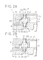
- FIGS. 2A and 2B are enlarged sectional views showing that the direction of a channel-switching plate is changed.
- FIG. 3 is an enlarged sectional view showing the structure of an amplifying valve.
- FIG. 4 is a perspective view showing a second embodiment of a directional control valve according to this invention.
- FIGS. 1 to 3 show a first embodiment of a pilot-operated directional control valve according to this invention.
- This directional control valve 1A is of a single pilot type and comprises a main valve 2 that switches a channel for a main fluid, a pilot valve 3 driven by a solenoid 3a, and an amplifying valve assembled into an adapter plate 4 between the main valve 2 and the pilot valve 3.
- the main valve 2 comprises a valve body 7 shaped like a long rectangular parallelepiped, and a first and a second piston boxes 11 and 12 mounted on the respective axial sides of the valve body 7.
- the valve body 7 is composed of a first body portion 7a occupying the most of the valve body and a second body portion 7b detachably mounted on the top surface of the first portion 7a using screws.
- the valve body 7 includes a pressure fluid supply port P provided at the center of the bottom surface of the first body portion 7a; a first and a second output ports A and B provided on the respective sides of the supply port P at an almost equal interval therefrom; a first and a second ejection ports EA and EB provided on the respective sides of the output ports A and B at an almost equal interval from the respective output ports; and a valve hole 13 into which these ports are opened.
- a valve disc 14 that switches the channel between the outputs ports A, B and the supply port P and ejection ports EA, EB is slidably inserted into the valve hole 13.
- an external pilot port X and a pilot ejection port PE that ejects a pilot fluid to the exterior are provided in the valve body 7 towards the first piston box 11.
- a first pressure chamber 11a having a larger diameter than the valve hole 13 is formed in the first piston box 11, and a first piston 15 is inserted into the first pressure chamber 11a in an airtight manner.
- a second pressure chamber 12a having a smaller diameter than the first pressure chamber 11a is formed in the second piston box 12, and a second piston 16 is inserted into the second pressure chamber 12a.
- a return spring 17 that urges the valve disc 13 toward the first piston 15 is provided between the second piston 16 and the valve disc 13.
- a plug chamber 21 in which a switching plug 20 is accommodated and which changes the directional control valve between the internal pilot type and the external pilot type is formed between the first and second body portions 7a and 7b of the valve body 7.
- the plug chamber 21 is formed in such a way as to extend across both the first and second body portions 7a and 7b due to dents provided in the respective portions.
- An external pilot channel 26 in communication with the external pilot port X is opened into a chamber portion 21a formed in the first body portion 7a, and an external pilot valve seat 23 in communication with the channel 26 is also provided in the chamber portion 21a.
- An internal pilot channel 19 branching from the supply port P is opened into a chamber portion 21b formed in the second body portion 7b, and an internal pilot valve seat 22 in communication with the channel 19 is also provided in the chamber portion 21b. Furthermore, a pilot input channel 28 in communication with a pilot inlet port (p) in the pilot valve 3 and a pilot return channel 29 that constantly guides a pilot fluid to the second pressure chamber 12a are opened into a chamber portion 21c located between both valve seats 22 and 23.
- the internal pilot channel 19 is formed from a groove cut into the second body portion 7b, and the pilot input channel 28 and the return channel 29 are formed from a groove cut into the second body portion 7b and a hole provided in the first body portion 7a.
- the channels and the plug chamber are formed by providing grooves and shallow dents in the first or second body portion 7a or 7b, making both processing and assembly much simpler than in conventional products in which deep holes of different diameters or bent through-holes are formed inside a single body.
- the switching plug 20 consists of two ends 20a and 20b of the same diameter that are closely fitted in the chamber portions 21a and 21b of the same diameter at the respective ends of the plug chamber 21 using seal rings 35; and an intermediate portion 20c of a larger diameter that is fitted in the chamber portion 21c of a larger diameter.
- the switching plug is accommodated in the plug chamber 21 in such a way that its axial direction can be changed by 180° .
- a poppet valve disc 31 is provided at one of the axial ends of the intermediate portion 20c to allow one of the two valve seats 22 and 23 to be selectively closed when the direction of the switching plug 20 is changed by 180 °.
- the entire intermediate portion 20c except for the valve disc 31 is formed to have a cross-shaped cross section, and its dented portion forms a communication path allowing one of the valves 22 and 23 which is open and the pilot input channel 28 to communicate mutually.
- the pilot valve 3 is configured as a three-port solenoid-operated valve, and comprises a pilot inlet port (p), a pilot outlet port (a), and a pilot ejection port (r) (for the ports (p), (a), and (r), see FIG. 3).
- the solenoid 3a is magnetized and demagnetized to switch the pilot output port (p) between the pilot inlet port (a) and the pilot ejection port (r) for communication.
- the pilot inlet port (p) is in communication with the pilot input channel 28 via the amplifying valve 5, as described above; the pilot output port (a), with a pressure chamber 50 in the amplifying valve 5; and the pilot ejection port (r), with the pilot ejection port PE through a pilot ejection channel 49.
- the solenoid 3a is supplied with power from a feeding plug 37 provided in the adapter plate 4, via an electric connector 38 and a printed circuit board 39 provided under the pilot valve 3 and on one side thereof, respectively.
- the amplifying valve 5 which is shown in FIG. 3 in detail, comprises an amplifying valve body 41 mounted in a mounting chamber 4a formed in the adapter plate 4; a valve seat member 42 mounted in an airtight manner in a sliding hole 41a located in the axial direction of the valve body 41; an amplifying valve disc 43 that slides through the sliding hole 41a in an airtight manner; and a return spring 44 that returns the amplifying valve disc 43 to its original position.
- An output valve seat 46 and an ejection valve seat 47 are formed opposite in the valve seat member 42.
- the space between the valve seats is in communication with the first pressure chamber 11a through the pilot output channel 48.
- the pilot input channel 28 is opened in the space in the sliding hole 41a located above the output valve seat 46, the space below the ejection valve seat 47 is in communication with the pilot ejection channel PE through the pilot ejection channel 49, and the pressure chamber 50 between the amplifying valve body 41 and the amplifying valve disc 43 is in communication with the pilot output port (a).
- the amplifying valve disc 43 includes a valve disc 43a that opens and closes the output and ejection valve seats 46 and 47 by means of sliding.
- a manually operated device 52 that enables a manual operation for allowing the pilot input channel 28 to communicate directly with the first pressure chamber 11a without using the amplifying valve 5 or the pilot valve 3 is provided in the first piston box 11 in such a way that the device can be pressed downward in the figure.
- the manually operated device 52 is normally positioned above in the figure by the urging force of the return spring 53 to allow the pilot input channel 28 to communicate with the pilot inlet port (p), and when pressed, allows the pilot input channel 28 to communicate directly with the first pressure chamber 11a.
- the manually operated device 52 can be pressed and released to drive the valve disc 14.
- a passage 54 that allows breathing chambers behind the first and second pistons 15 and 16 to communicate mutually is formed in the valve disc 14, and the breathing chamber behind the first piston 15 is in communication with the pilot ejection port PE through the pilot ejection channel 49.
- Reference numeral 56 in FIG. 1 is an indicator lamp indicating that power is being supplied to the solenoid 3a mounted on the printed circuit board 39, and a transparent or semi-transparent indicating window 58 through which the operator visually checks whether the indicator lamp 56 is lit is provided in a cover 57 covering the pilot valve 3 and the printed circuit board 39.
- FIGS. 1 and 2A shows that the directional control valve lA acts as the internal pilot type when the switching plug 20 is mounted in the direction in which the valve disc 31 closes the external pilot valve seat 23 while the internal pilot channel 19 and the pilot input channel 28 mutually communicate through the internal pilot valve seat 22.
- a pilot fluid is supplied to the pilot valve 3 and the amplifying valve 5 from the supply port P through the internal pilot channel 19 and the pilot input channel 28.
- FIG. 1 shows that the solenoid 3a is demagnetized. Since the pilot outlet port (a) in the pilot valve 3 is in communication with the pilot ejection port (r) and the amplifying valve disc 43 is positioned above in the figure by the urging force of the return spring 44, the amplifying valve disc 44a closes the output valve seat 46 while opening the ejection valve seat 47.
- the pilot fluid in the first pressure chamber lla is ejected from the pilot ejection port PE through the pilot output channel 48, the ejection valve seat 47, and the pilot ejection channel 49.
- the valve disc 14 is moved leftward in the figure by two forces, the impelling force of compressed air supplied to the second pressure chamber 12a through the return channel 29 and the urging force of the return spring 17, thereby allowing the supply port P to communicate with the second output port B while allowing the first output port A to communicate with the first ejection port EA.
- the pilot inlet port (p) and pilot output port (a) in the pilot valve 3 communicate mutually to supply a pilot fluid to the pressure chamber 50 in the amplifying valve 5. Then, the amplifying valve disc 43 moves downward to cause the amplifying valve disc 43a to open the output valve seat 46 while closing the ejection valve seat 47, thereby supplying an internal pilot fluid to the first pressure chamber 11a.
- the difference in diameter between the two pistons 15 and 16 causes the valve disc 14 to move rightward in the figure, thereby allowing the supply port P to communicate with the first output port A while allowing the second output port B to communicate with the second ejection port EB.
- the pilot output port (a) communicates with the pilot ejection port (r) to eject the pilot fluid supplied to the pressure chamber 59 in the amplifying valve 5, from the pilot ejection port PE to the exterior through the pilot ejection channel 49. Then, the urging force of the return spring 44 causes the amplifying valve disc 43 to move upward in the figure, thereby allowing the amplifying valve disc 43a to close the output valve seat 46 while opening the ejection valve seat 47.
- the pilot fluid supplied to the first pressure chamber 11a is ejected from the pilot ejection port PE to the exterior through the pilot output channel 48, the ejection valve seat 47, and the pilot ejection channel 49.
- the combination of two forces, the impelling force of compressed air supplied to the second pressure chamber 12a and the urging force of the return spring 17, then causes the valve disc 14 to return to its original position, thereby allowing the supply port P to communicate with the output port B while allowing the first output port A to communicate with the first ejection port EA.
- the valve disc 31 closes the internal pilot valve seat 22 while the external pilot channel 26 and the pilot input channel 28 communicate mutually through the external pilot valve seat 23, thereby changing the directional control valve to the external pilot type. Accordingly, the pilot fluid is supplied from the external pilot port X through the pilot input channel 28 to the pilot valve 3 and the amplifying valve 5.
- the valve body 7 comprises the first and second body portions 7a and 7b, and the channels and the plug chamber 21 are formed by providing grooves and shallow dents in the first or second body portion 7a or 7b, making processing and assembly much simpler than in conventional products in which deep holes of different diameters or bent through-holes are formed inside a single body.
- this embodiment requires only a small output of pilot fluid from the pilot valve 3 to drive the amplifying valve body 43 having a much smaller diameter than the valve disc 14 of the main valve 2, thereby reducing the size and costs of the pilot valve 3 driven by the solenoid 3a.
- FIG. 4 shows a second embodiment.
- a directional control valve 1B according to the second embodiment appears very similar to the directional control valve 1A according to the first embodiment, but is of a double-solenoid type and differs from the first embodiment in that a main valve is switched by two pilot valves. That is, in FIG. 4, the valve disc is switched by supplying a pilot fluid to the pistons provided in the first and second piston boxes 11B and 12B, respectively, on the respective sides of the main valve 2B, using the pilot valve and amplifying valve corresponding these pistons.
- two pilot valves are integrated inside a cover 57B
- two amplifying valves are integrated inside an adapter plate 4B
- two manually operated devices 52 are integrated inside the first piston box 11B.
- the second embodiment uses substantially the same switching mechanism as in the first embodiment to switch between the internal and external pilot types.
- the directional control valves according to the above embodiments are all of a five-port type, but this invention is not limited to this type and four- or three-port types may be used as well.
Landscapes
- Engineering & Computer Science (AREA)
- General Engineering & Computer Science (AREA)
- Mechanical Engineering (AREA)
- Physics & Mathematics (AREA)
- Fluid Mechanics (AREA)
- Fluid-Driven Valves (AREA)
- Valve Housings (AREA)
- Multiple-Way Valves (AREA)
Applications Claiming Priority (3)
| Application Number | Priority Date | Filing Date | Title |
|---|---|---|---|
| JP304855/97 | 1997-10-20 | ||
| JP30485597 | 1997-10-20 | ||
| JP30485597A JP3959563B2 (ja) | 1997-10-20 | 1997-10-20 | パイロット式切換弁 |
Publications (2)
| Publication Number | Publication Date |
|---|---|
| EP0911559A1 true EP0911559A1 (de) | 1999-04-28 |
| EP0911559B1 EP0911559B1 (de) | 2003-02-12 |
Family
ID=17938099
Family Applications (1)
| Application Number | Title | Priority Date | Filing Date |
|---|---|---|---|
| EP19980308512 Expired - Lifetime EP0911559B1 (de) | 1997-10-20 | 1998-10-19 | Vorgesteuertes Lenkungsregelventil |
Country Status (7)
| Country | Link |
|---|---|
| US (1) | US5964244A (de) |
| EP (1) | EP0911559B1 (de) |
| JP (1) | JP3959563B2 (de) |
| KR (1) | KR100302412B1 (de) |
| CN (1) | CN1083547C (de) |
| DE (1) | DE69811309T2 (de) |
| TW (1) | TW364563U (de) |
Families Citing this family (10)
| Publication number | Priority date | Publication date | Assignee | Title |
|---|---|---|---|---|
| JPH11325296A (ja) * | 1998-05-14 | 1999-11-26 | Smc Corp | ベース搭載形電磁弁 |
| US6164323A (en) * | 1999-07-12 | 2000-12-26 | Numatics, Incorporated | Solenoid valve control system |
| FR2807793B1 (fr) * | 2000-04-17 | 2002-05-31 | Parker Hannifin Rak Sa | Module d'interface pour ilot de distributeurs electropneumatiques |
| JP4003219B2 (ja) * | 2002-06-25 | 2007-11-07 | Smc株式会社 | 位置検出機構を備えたマニホールドバルブ |
| DE202006000624U1 (de) * | 2006-01-17 | 2006-03-09 | Krauss-Maffei Kunststofftechnik Gmbh | Umschaltventil |
| JP2008209009A (ja) * | 2008-06-06 | 2008-09-11 | Koganei Corp | 電磁弁 |
| CN102308131B (zh) * | 2008-12-06 | 2014-01-08 | 盾安美斯泰克有限公司 | 流体流动控制组件 |
| US9909678B2 (en) * | 2010-08-10 | 2018-03-06 | Ross Europa Gmbh | Two part valve |
| US10274105B2 (en) * | 2014-09-24 | 2019-04-30 | Eagle Industry Co., Ltd. | Spool valve |
| SG11201912123YA (en) | 2017-06-16 | 2020-01-30 | Ican Company Ltd | Disc brake device |
Citations (8)
| Publication number | Priority date | Publication date | Assignee | Title |
|---|---|---|---|---|
| US2295111A (en) * | 1940-01-02 | 1942-09-08 | Smith & Sons Ltd S | Manufacture of tubular valve members |
| DE1127675B (de) * | 1958-04-02 | 1962-04-12 | Concordia | Steuerschieber |
| FR2257837A1 (en) * | 1973-08-28 | 1975-08-08 | Wabco Westinghouse | Spool type distributor for pressure fluid - has apertured selector plate controlling pilot fluid and line flow |
| JPS6417078U (de) | 1987-07-20 | 1989-01-27 | ||
| JPH01163270U (de) | 1988-05-06 | 1989-11-14 | ||
| US5086803A (en) * | 1989-12-20 | 1992-02-11 | Taiyo Ltd. | Solenoid valve and manifold assembly |
| US5222715A (en) * | 1992-06-01 | 1993-06-29 | Mead Fluid Dynamics, Inc. | Valve construction |
| US5487409A (en) * | 1993-07-24 | 1996-01-30 | Festo Kg | Spool valve |
Family Cites Families (3)
| Publication number | Priority date | Publication date | Assignee | Title |
|---|---|---|---|---|
| US4253481A (en) * | 1979-05-07 | 1981-03-03 | Gilmore Valve Company | Cushioned shuttle valve |
| JPH0432538Y2 (de) * | 1988-05-30 | 1992-08-05 | ||
| JP3456776B2 (ja) * | 1994-09-22 | 2003-10-14 | Smc株式会社 | パイロット形方向切換弁 |
-
1997
- 1997-10-20 JP JP30485597A patent/JP3959563B2/ja not_active Expired - Fee Related
-
1998
- 1998-09-29 TW TW087216145U patent/TW364563U/zh unknown
- 1998-09-30 US US09/162,997 patent/US5964244A/en not_active Expired - Fee Related
- 1998-10-19 KR KR1019980043630A patent/KR100302412B1/ko not_active Expired - Fee Related
- 1998-10-19 DE DE69811309T patent/DE69811309T2/de not_active Expired - Fee Related
- 1998-10-19 EP EP19980308512 patent/EP0911559B1/de not_active Expired - Lifetime
- 1998-10-20 CN CN98120989A patent/CN1083547C/zh not_active Expired - Fee Related
Patent Citations (8)
| Publication number | Priority date | Publication date | Assignee | Title |
|---|---|---|---|---|
| US2295111A (en) * | 1940-01-02 | 1942-09-08 | Smith & Sons Ltd S | Manufacture of tubular valve members |
| DE1127675B (de) * | 1958-04-02 | 1962-04-12 | Concordia | Steuerschieber |
| FR2257837A1 (en) * | 1973-08-28 | 1975-08-08 | Wabco Westinghouse | Spool type distributor for pressure fluid - has apertured selector plate controlling pilot fluid and line flow |
| JPS6417078U (de) | 1987-07-20 | 1989-01-27 | ||
| JPH01163270U (de) | 1988-05-06 | 1989-11-14 | ||
| US5086803A (en) * | 1989-12-20 | 1992-02-11 | Taiyo Ltd. | Solenoid valve and manifold assembly |
| US5222715A (en) * | 1992-06-01 | 1993-06-29 | Mead Fluid Dynamics, Inc. | Valve construction |
| US5487409A (en) * | 1993-07-24 | 1996-01-30 | Festo Kg | Spool valve |
Also Published As
| Publication number | Publication date |
|---|---|
| US5964244A (en) | 1999-10-12 |
| JPH11125362A (ja) | 1999-05-11 |
| JP3959563B2 (ja) | 2007-08-15 |
| KR100302412B1 (ko) | 2001-12-01 |
| TW364563U (en) | 1999-07-11 |
| DE69811309D1 (de) | 2003-03-20 |
| KR19990037186A (ko) | 1999-05-25 |
| CN1083547C (zh) | 2002-04-24 |
| CN1216809A (zh) | 1999-05-19 |
| DE69811309T2 (de) | 2003-12-11 |
| EP0911559B1 (de) | 2003-02-12 |
Similar Documents
| Publication | Publication Date | Title |
|---|---|---|
| US5868157A (en) | Pilot transfer valve | |
| US6109291A (en) | Pilot 5-port transfer valve | |
| US5699834A (en) | Manifold-type solenoid valves | |
| KR100216970B1 (ko) | 파일로트형 방향 전환 밸브 | |
| EP0846872B1 (de) | Steuerventilverteilerplatte mit innerer oder äusserer Steuerschaltung | |
| EP0915259B1 (de) | Verbindungseinrichtung für ein Wegeventil | |
| US6167901B1 (en) | Pilot 3-port transfer valve | |
| EP0713991B1 (de) | Doppel-Elektromagnetventil | |
| US5964244A (en) | Pilot-operated directional control valve | |
| KR100294363B1 (ko) | 베이스부착형변환밸브에부착하기위한압력조절밸브 | |
| US5845679A (en) | Pilot selector valve | |
| EP0898103B1 (de) | Magnetventil mit drei Anschlüssen im Gehäuse eines Magnetventils mit fünf Anschlüssen | |
| EP0822361B1 (de) | An ein mehrstufiges Umschaltventil angeflanschter Druckregler | |
| EP0897077B1 (de) | Magnetventil mit zwei Anschlüssen im Gehäuse eines Magnetventils mit fünf Anschlüssen | |
| US5996609A (en) | Pilot-operated directional control valve | |
| EP0719950B1 (de) | Sitzwegeventil | |
| EP0800002B1 (de) | Elektromagnetisch betätigtes Steuerventil | |
| EP0348058A2 (de) | Flüssigkeit lenkendes Ventil | |
| TWI921541B (zh) | 真空噴射器及具備該真空噴射器的真空產生裝置 | |
| HK1003661A (en) | Solenoid pilot valve | |
| JPH06193769A (ja) | 複合電磁切換弁 |
Legal Events
| Date | Code | Title | Description |
|---|---|---|---|
| PUAI | Public reference made under article 153(3) epc to a published international application that has entered the european phase |
Free format text: ORIGINAL CODE: 0009012 |
|
| 17P | Request for examination filed |
Effective date: 19981117 |
|
| AK | Designated contracting states |
Kind code of ref document: A1 Designated state(s): DE FR GB IT |
|
| AX | Request for extension of the european patent |
Free format text: AL;LT;LV;MK;RO;SI |
|
| AKX | Designation fees paid |
Free format text: DE FR GB IT |
|
| 17Q | First examination report despatched |
Effective date: 20000523 |
|
| GRAG | Despatch of communication of intention to grant |
Free format text: ORIGINAL CODE: EPIDOS AGRA |
|
| GRAG | Despatch of communication of intention to grant |
Free format text: ORIGINAL CODE: EPIDOS AGRA |
|
| GRAH | Despatch of communication of intention to grant a patent |
Free format text: ORIGINAL CODE: EPIDOS IGRA |
|
| GRAH | Despatch of communication of intention to grant a patent |
Free format text: ORIGINAL CODE: EPIDOS IGRA |
|
| GRAA | (expected) grant |
Free format text: ORIGINAL CODE: 0009210 |
|
| RIN1 | Information on inventor provided before grant (corrected) |
Inventor name: ISHIKAWA, MAKOTO, SMC CORP.TSUKUBA TECH.CENTER Inventor name: HIRAMATSU, KAZUO, SMC CORP.TSUKUBA TECH.CENTER |
|
| AK | Designated contracting states |
Designated state(s): DE FR GB IT |
|
| PG25 | Lapsed in a contracting state [announced via postgrant information from national office to epo] |
Ref country code: IT Free format text: LAPSE BECAUSE OF FAILURE TO SUBMIT A TRANSLATION OF THE DESCRIPTION OR TO PAY THE FEE WITHIN THE PRESCRIBED TIME-LIMIT;WARNING: LAPSES OF ITALIAN PATENTS WITH EFFECTIVE DATE BEFORE 2007 MAY HAVE OCCURRED AT ANY TIME BEFORE 2007. THE CORRECT EFFECTIVE DATE MAY BE DIFFERENT FROM THE ONE RECORDED. Effective date: 20030212 Ref country code: FR Free format text: LAPSE BECAUSE OF FAILURE TO SUBMIT A TRANSLATION OF THE DESCRIPTION OR TO PAY THE FEE WITHIN THE PRESCRIBED TIME-LIMIT Effective date: 20030212 |
|
| REG | Reference to a national code |
Ref country code: GB Ref legal event code: FG4D |
|
| REF | Corresponds to: |
Ref document number: 69811309 Country of ref document: DE Date of ref document: 20030320 Kind code of ref document: P |
|
| PG25 | Lapsed in a contracting state [announced via postgrant information from national office to epo] |
Ref country code: GB Free format text: LAPSE BECAUSE OF NON-PAYMENT OF DUE FEES Effective date: 20031019 |
|
| PLBE | No opposition filed within time limit |
Free format text: ORIGINAL CODE: 0009261 |
|
| STAA | Information on the status of an ep patent application or granted ep patent |
Free format text: STATUS: NO OPPOSITION FILED WITHIN TIME LIMIT |
|
| EN | Fr: translation not filed | ||
| 26N | No opposition filed |
Effective date: 20031113 |
|
| GBPC | Gb: european patent ceased through non-payment of renewal fee |
Effective date: 20031019 |
|
| PGFP | Annual fee paid to national office [announced via postgrant information from national office to epo] |
Ref country code: DE Payment date: 20071025 Year of fee payment: 10 |
|
| PG25 | Lapsed in a contracting state [announced via postgrant information from national office to epo] |
Ref country code: DE Free format text: LAPSE BECAUSE OF NON-PAYMENT OF DUE FEES Effective date: 20090501 |