EP0911587A1 - Dispositif de conditionnement d'air - Google Patents
Dispositif de conditionnement d'air Download PDFInfo
- Publication number
- EP0911587A1 EP0911587A1 EP97810803A EP97810803A EP0911587A1 EP 0911587 A1 EP0911587 A1 EP 0911587A1 EP 97810803 A EP97810803 A EP 97810803A EP 97810803 A EP97810803 A EP 97810803A EP 0911587 A1 EP0911587 A1 EP 0911587A1
- Authority
- EP
- European Patent Office
- Prior art keywords
- evaporator
- air
- air conditioner
- frame
- louvers
- Prior art date
- Legal status (The legal status is an assumption and is not a legal conclusion. Google has not performed a legal analysis and makes no representation as to the accuracy of the status listed.)
- Withdrawn
Links
- 230000003750 conditioning effect Effects 0.000 claims abstract description 6
- 239000003507 refrigerant Substances 0.000 claims description 6
- 238000010438 heat treatment Methods 0.000 claims description 4
- 239000000725 suspension Substances 0.000 claims description 4
- 239000000463 material Substances 0.000 claims description 3
- 238000004887 air purification Methods 0.000 claims description 2
- 238000005452 bending Methods 0.000 claims 1
- 238000004378 air conditioning Methods 0.000 description 6
- 238000001816 cooling Methods 0.000 description 2
- 238000004519 manufacturing process Methods 0.000 description 2
- 238000010792 warming Methods 0.000 description 2
- 238000009825 accumulation Methods 0.000 description 1
- 230000000694 effects Effects 0.000 description 1
- 238000005516 engineering process Methods 0.000 description 1
- 238000001704 evaporation Methods 0.000 description 1
- 230000008020 evaporation Effects 0.000 description 1
- 238000000034 method Methods 0.000 description 1
- 230000002093 peripheral effect Effects 0.000 description 1
- 238000010257 thawing Methods 0.000 description 1
Images

Classifications
-
- F—MECHANICAL ENGINEERING; LIGHTING; HEATING; WEAPONS; BLASTING
- F24—HEATING; RANGES; VENTILATING
- F24F—AIR-CONDITIONING; AIR-HUMIDIFICATION; VENTILATION; USE OF AIR CURRENTS FOR SCREENING
- F24F13/00—Details common to, or for air-conditioning, air-humidification, ventilation or use of air currents for screening
- F24F13/20—Casings or covers
-
- F—MECHANICAL ENGINEERING; LIGHTING; HEATING; WEAPONS; BLASTING
- F24—HEATING; RANGES; VENTILATING
- F24F—AIR-CONDITIONING; AIR-HUMIDIFICATION; VENTILATION; USE OF AIR CURRENTS FOR SCREENING
- F24F1/00—Room units for air-conditioning, e.g. separate or self-contained units or units receiving primary air from a central station
- F24F1/0007—Indoor units, e.g. fan coil units
- F24F1/0043—Indoor units, e.g. fan coil units characterised by mounting arrangements
- F24F1/0057—Indoor units, e.g. fan coil units characterised by mounting arrangements mounted in or on a wall
-
- F—MECHANICAL ENGINEERING; LIGHTING; HEATING; WEAPONS; BLASTING
- F24—HEATING; RANGES; VENTILATING
- F24F—AIR-CONDITIONING; AIR-HUMIDIFICATION; VENTILATION; USE OF AIR CURRENTS FOR SCREENING
- F24F1/00—Room units for air-conditioning, e.g. separate or self-contained units or units receiving primary air from a central station
- F24F1/0007—Indoor units, e.g. fan coil units
- F24F1/0059—Indoor units, e.g. fan coil units characterised by heat exchangers
- F24F1/0063—Indoor units, e.g. fan coil units characterised by heat exchangers by the mounting or arrangement of the heat exchangers
-
- F—MECHANICAL ENGINEERING; LIGHTING; HEATING; WEAPONS; BLASTING
- F24—HEATING; RANGES; VENTILATING
- F24F—AIR-CONDITIONING; AIR-HUMIDIFICATION; VENTILATION; USE OF AIR CURRENTS FOR SCREENING
- F24F1/00—Room units for air-conditioning, e.g. separate or self-contained units or units receiving primary air from a central station
- F24F1/0007—Indoor units, e.g. fan coil units
- F24F1/0059—Indoor units, e.g. fan coil units characterised by heat exchangers
- F24F1/0067—Indoor units, e.g. fan coil units characterised by heat exchangers by the shape of the heat exchangers or of parts thereof, e.g. of their fins
-
- F—MECHANICAL ENGINEERING; LIGHTING; HEATING; WEAPONS; BLASTING
- F24—HEATING; RANGES; VENTILATING
- F24F—AIR-CONDITIONING; AIR-HUMIDIFICATION; VENTILATION; USE OF AIR CURRENTS FOR SCREENING
- F24F1/00—Room units for air-conditioning, e.g. separate or self-contained units or units receiving primary air from a central station
- F24F1/0007—Indoor units, e.g. fan coil units
- F24F1/0071—Indoor units, e.g. fan coil units with means for purifying supplied air
-
- F—MECHANICAL ENGINEERING; LIGHTING; HEATING; WEAPONS; BLASTING
- F24—HEATING; RANGES; VENTILATING
- F24F—AIR-CONDITIONING; AIR-HUMIDIFICATION; VENTILATION; USE OF AIR CURRENTS FOR SCREENING
- F24F1/00—Room units for air-conditioning, e.g. separate or self-contained units or units receiving primary air from a central station
- F24F1/0007—Indoor units, e.g. fan coil units
- F24F1/009—Indoor units, e.g. fan coil units characterised by heating arrangements
- F24F1/0093—Indoor units, e.g. fan coil units characterised by heating arrangements with additional radiant heat-discharging elements, e.g. electric heaters
-
- F—MECHANICAL ENGINEERING; LIGHTING; HEATING; WEAPONS; BLASTING
- F24—HEATING; RANGES; VENTILATING
- F24F—AIR-CONDITIONING; AIR-HUMIDIFICATION; VENTILATION; USE OF AIR CURRENTS FOR SCREENING
- F24F11/00—Control or safety arrangements
- F24F11/50—Control or safety arrangements characterised by user interfaces or communication
- F24F11/56—Remote control
-
- F—MECHANICAL ENGINEERING; LIGHTING; HEATING; WEAPONS; BLASTING
- F24—HEATING; RANGES; VENTILATING
- F24F—AIR-CONDITIONING; AIR-HUMIDIFICATION; VENTILATION; USE OF AIR CURRENTS FOR SCREENING
- F24F2221/00—Details or features not otherwise provided for
- F24F2221/26—Details or features not otherwise provided for improving the aesthetic appearance
Definitions
- the present invention relates to a room air conditioner, and more particularly to a separate type air conditioner that has patterned louvers to provide aesthetic appearance. Besides, several conditioner units may be stacked or juxtaposed to increase the size and conditioning capacity of the conditioner as a whole.
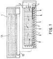
- Fig. 1 shows a conventional air conditioner.
- An evaporation 2 is installed inside a cabinet 1.
- a blower 3 is disposed at a lower end of the evaporator 2.
- the blower 3 is pivotally connected to a motor 4 at one side thereof.
- Louvers 5 are disposed below the blower 3.
- the cabinet 1 is provided with a plurality of air inlets 1A corresponding to the front side of the evaporator 2 and air outlets 1B corresponding to the louvers 5.
- the blower 3 is actuated so that indoor air is drawn via the air inlets 1A into the evaporator 2 which absorbs the heat of the drawn-in air or the drawn-in air absorbs the high heat of the evaporator 2 before being released to the room.
- Such conventional air conditioners have the following drawbacks:
- a primary object of the present invention is to provide an air conditioner in which several conditioner units may be stacked or juxtaposed to form a larger air conditioner.
- the specification of the evaporator structure of the air conditioner is standard and of a smaller size. It is accommodated within a cabinet of a determined specification.
- Several cabinets can be stacked or juxtaposed on a vertical surface allow expansion of conditioning capacity. For instance, when each conditioner unit is designed to have heat dissipating capacity in the range of 6000-15000 BTU, a single row, two rows, or three rows of evaporators and blower motors can be used to provide sufficient room air conditioning effects in the range of 15000 BTU.
- Another object of the present invention is to provide an air conditioner in. which the evaporator structure is provided with electrical heating elements to directly heat the air so that there is no need to provide reverse refrigerant flow or actuate the outdoor unit, thereby eliminating the problem of frost accumulation on outdoor units in the prior art.
- a further object of the present invention is to provide an air condition in which the louvers are provided with patterns that will display when the louvers are all closed, thus adding aesthetic quality to the air conditioner.
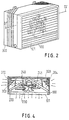
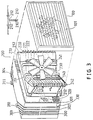
- the present invention essentially comprises a frame body 100 accommodating therein louvers 101, an evaporator structure 200, and a rear cabinet 300.
- the evaporator structure 200 includes a base 210, an evaporator 220 disposed on the base 210, a mounting frame 211, and a blower 230 mounted on the mounting frame 211.
- the mounting frame 211 straddles over the evaporator 220, and the blower is located between the evaporator 220 and the frame 100.
- the evaporator 220 is a plate structure in which multiple refrigerant ducts are disposed.
- the middle section of the evaporator 220 bent s towards the base to connect therewith, while the two ends of the evaporator 220 tilt away from the base 210 so that there are more space between the ends of the evaporator 220 and the base 210.
- a moisture collector duct 240 is connected to a lower rim of the evaporator 220 so that moisture formed on the surface of the evaporator 220 may be collected in the moisture collector duct 240 below and discharged. When two or more bases 210 are stacked, the moisture collector ducts 240 can be inter-connected. Electrical heating elements 240, 241 may be mounted on the surface of the evaporator 220 at suitable positions to directly heat the air so that the present invention can also provide warm air.
- the entire evaporator structure 200 is inserted into the rear cabinet 300 via a hollow 301 at one end of the rear cabinet 300 and is secured to the inner walls of the rear cabinet 300 by screws or other means, such that the blower 230 sends out air currents via the hollow 301.
- the interior space of the rear cabinet 300 is slightly larger than the base 210 and the evaporator 220, so that air flowing in between the ends of the evaporator 220 and the base 210 may be discharged by means of the blower 230 when flowing past the upper and lower rims of the evaporator 220.
- the four walls of the rear cabinet 300 are provided with air inlets 302, 303, 304,..., which are provided with filter materials 320 and air purification means so that the induced air can pass through the air inlets 302, 303,304,..., and the filter materials 320 into the rear cabinet 300 to contact the evaporator 220 to thereby generate cooling or warming effects.
- a pipe hole 330 is further provided on the rear cabinet 300 at a suitable position for linking the evaporator 200 to other equipment or systems.
- suspension hooks 310, 311 adapted to suspend the present invention on an upright surface.
- the frame 100 is securely provided at the four sides of that side of the rear cabinet 300 with the hollow 301.
- the louvers 101 arranged in the frame 100 have patterns thereon. When the louvers are all closed, the patterns will be displaced to add aesthetic quality to the present invention.
- the blower 230 is actuated and the cooling or warming mode is selected.
- Air in the rear cabinet 300 is passed through the evaporator 220 and the electrical heating elements 240, 240 to condition the temperature of the air which is released to the room via the louvers 101.
- Indoor air is drawn via the air inlets 302, 303,...into the rear cabinet 300 and in between the two ends of the evaporator 220 and the base 210 to contact the surfaces of the evaporator 220.
- the air then flows past the upper and lower rims of the evaporator 220 to the blower 230 in front of the evaporator 220 and is then sent out.
- the outer periphery of the frame 100 can be configured to be an artistic picture frame 102, and an inner frame 102 having louvers 101 installed therein is mounted in the picture frame 102 to further enhance the aesthetic quality of the present invention.
- the picture frame 102 can further be provided with a trigger element 120 at that side orienting towards rear cabinet 300, the trigger element 120 being linked to the louvers 101.
- the louvers may rhythmically open or close.
- a step motor 150 may be provided at a suitable position to drive the trigger element 120.
- the trigger element 120 is driven to cause the louvers to rhythmically swing to provide mobile patterns while directing the flow of air to the room.
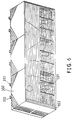
- a number of bases 210 each as a single unit, can be stacked or juxtaposed to form an air conditioner of a larger size. Since each rear cabinet 300 is provided with suspension hooks 310, 311, the present invention, even when stacked or juxtaposed to form a larger structure can be firmly secured to vertical surfaces such as walls. Supposing each unit can achieve 15000 BTU air conditioning capacity, the three units shown in Fig. 6 can achieve thrice the capacity. The units are directly secured or stacked to adjacent units by means of securing holes 212. As can be appreciated from the above description, the present invention allows expansion of the size of the air conditioner in various ways using identical air conditioning units, which is very cost efficient.
Landscapes
- Engineering & Computer Science (AREA)
- Chemical & Material Sciences (AREA)
- Combustion & Propulsion (AREA)
- Mechanical Engineering (AREA)
- General Engineering & Computer Science (AREA)
- Physics & Mathematics (AREA)
- Thermal Sciences (AREA)
- Air Filters, Heat-Exchange Apparatuses, And Housings Of Air-Conditioning Units (AREA)
Priority Applications (1)
| Application Number | Priority Date | Filing Date | Title |
|---|---|---|---|
| EP97810803A EP0911587A1 (fr) | 1997-10-28 | 1997-10-28 | Dispositif de conditionnement d'air |
Applications Claiming Priority (1)
| Application Number | Priority Date | Filing Date | Title |
|---|---|---|---|
| EP97810803A EP0911587A1 (fr) | 1997-10-28 | 1997-10-28 | Dispositif de conditionnement d'air |
Publications (1)
| Publication Number | Publication Date |
|---|---|
| EP0911587A1 true EP0911587A1 (fr) | 1999-04-28 |
Family
ID=8230444
Family Applications (1)
| Application Number | Title | Priority Date | Filing Date |
|---|---|---|---|
| EP97810803A Withdrawn EP0911587A1 (fr) | 1997-10-28 | 1997-10-28 | Dispositif de conditionnement d'air |
Country Status (1)
| Country | Link |
|---|---|
| EP (1) | EP0911587A1 (fr) |
Cited By (5)
| Publication number | Priority date | Publication date | Assignee | Title |
|---|---|---|---|---|
| WO2008106185A1 (fr) * | 2007-03-01 | 2008-09-04 | Jack Richards | Dispositif de circulation d'air avec affichage d'images graphiques |
| EP1878977A3 (fr) * | 2006-07-13 | 2010-11-17 | LG Electronics Inc. | Climatiseur ayant une fonction d'affichage d'images |
| CN108800528A (zh) * | 2018-07-11 | 2018-11-13 | 苏州虎皇建设发展有限公司 | 一种具有稳定支撑功能的空调用散热基座 |
| CN112178781A (zh) * | 2020-10-16 | 2021-01-05 | 珠海格力电器股份有限公司 | 一种柜式空调器 |
| EP3649407A4 (fr) * | 2017-07-07 | 2022-03-02 | Techfresh Pty Ltd | Système de traitement d'air |
Citations (4)
| Publication number | Priority date | Publication date | Assignee | Title |
|---|---|---|---|---|
| US5263529A (en) * | 1992-03-02 | 1993-11-23 | Landis Erma E | Decorative decal system for louvered devices |
| EP0668473A2 (fr) * | 1994-02-21 | 1995-08-23 | Kabushiki Kaisha Toshiba | Machine pour le conditionnement d'air |
| GB2305500A (en) * | 1995-09-25 | 1997-04-09 | Mitsubishi Electric Corp | Fan units |
| US5669229A (en) * | 1995-05-30 | 1997-09-23 | Mitsubishi Jukogyo Kabushiki Kaisha | Ceiling-mounted type air conditioner |
-
1997
- 1997-10-28 EP EP97810803A patent/EP0911587A1/fr not_active Withdrawn
Patent Citations (4)
| Publication number | Priority date | Publication date | Assignee | Title |
|---|---|---|---|---|
| US5263529A (en) * | 1992-03-02 | 1993-11-23 | Landis Erma E | Decorative decal system for louvered devices |
| EP0668473A2 (fr) * | 1994-02-21 | 1995-08-23 | Kabushiki Kaisha Toshiba | Machine pour le conditionnement d'air |
| US5669229A (en) * | 1995-05-30 | 1997-09-23 | Mitsubishi Jukogyo Kabushiki Kaisha | Ceiling-mounted type air conditioner |
| GB2305500A (en) * | 1995-09-25 | 1997-04-09 | Mitsubishi Electric Corp | Fan units |
Cited By (5)
| Publication number | Priority date | Publication date | Assignee | Title |
|---|---|---|---|---|
| EP1878977A3 (fr) * | 2006-07-13 | 2010-11-17 | LG Electronics Inc. | Climatiseur ayant une fonction d'affichage d'images |
| WO2008106185A1 (fr) * | 2007-03-01 | 2008-09-04 | Jack Richards | Dispositif de circulation d'air avec affichage d'images graphiques |
| EP3649407A4 (fr) * | 2017-07-07 | 2022-03-02 | Techfresh Pty Ltd | Système de traitement d'air |
| CN108800528A (zh) * | 2018-07-11 | 2018-11-13 | 苏州虎皇建设发展有限公司 | 一种具有稳定支撑功能的空调用散热基座 |
| CN112178781A (zh) * | 2020-10-16 | 2021-01-05 | 珠海格力电器股份有限公司 | 一种柜式空调器 |
Similar Documents
| Publication | Publication Date | Title |
|---|---|---|
| KR100356245B1 (ko) | 창문형 실내 공조 장치 | |
| BRPI0904865A2 (pt) | aparelho modular de ar condicionado do tipo split | |
| US6318105B1 (en) | Control box for a room air conditioner | |
| AU2019242466B2 (en) | Ceiling-embedded air conditioner | |
| US6023936A (en) | Indoor unit of an air conditioner | |
| EP1255084B1 (fr) | Déhumidificateur | |
| JP2983871B2 (ja) | 空気調和機 | |
| US6022270A (en) | Air conditioner front grille with inserts for brand differentiation | |
| US6301914B1 (en) | Room air conditioner having outdoor power cord | |
| JPH05296555A (ja) | 風向変更装置 | |
| CN1178889A (zh) | 图框式可堆叠相接的空调室内机 | |
| JPH11287474A (ja) | 窓型エアコンのファンケ―シング | |
| JP3050175U (ja) | 分離型ルームエアコンの拡張可能な室内機 | |
| JP3219631B2 (ja) | 空気調和機 | |
| KR200186559Y1 (ko) | 일체형공기조화기 | |
| KR200165386Y1 (ko) | 일체형 공기조화기 | |
| KR200148473Y1 (ko) | 공기조절기의 송풍구조 | |
| KR100337903B1 (ko) | 벽걸이형 룸 에어컨의 고정브라켓 | |
| AU2019242465B2 (en) | Ceiling embedded air conditioner | |
| AU2019242467B2 (en) | Ceiling-embedded air conditioner | |
| JP7037072B2 (ja) | 空気調和装置 | |
| KR200198158Y1 (ko) | 공기조화기용증발기의고정구조 | |
| KR0150608B1 (ko) | 공기조화기의 가변형 냉기토출구 | |
| KR200198161Y1 (ko) | 분리형공기조화기의실외기결합구조 | |
| KR200182197Y1 (ko) | 멀티 에어콘 실외기의 압축기 및 응축기 배치구조 |
Legal Events
| Date | Code | Title | Description |
|---|---|---|---|
| PUAI | Public reference made under article 153(3) epc to a published international application that has entered the european phase |
Free format text: ORIGINAL CODE: 0009012 |
|
| AK | Designated contracting states |
Kind code of ref document: A1 Designated state(s): AT BE CH DE DK ES FI FR GB GR IE IT LI LU MC NL PT SE |
|
| AKX | Designation fees paid | ||
| REG | Reference to a national code |
Ref country code: DE Ref legal event code: 8566 |
|
| STAA | Information on the status of an ep patent application or granted ep patent |
Free format text: STATUS: THE APPLICATION IS DEEMED TO BE WITHDRAWN |
|
| 18D | Application deemed to be withdrawn |
Effective date: 19991029 |