EP0911612A2 - Dispositif de mesure de longeurs et machine pourvue de ce dispositif - Google Patents
Dispositif de mesure de longeurs et machine pourvue de ce dispositif Download PDFInfo
- Publication number
- EP0911612A2 EP0911612A2 EP98119002A EP98119002A EP0911612A2 EP 0911612 A2 EP0911612 A2 EP 0911612A2 EP 98119002 A EP98119002 A EP 98119002A EP 98119002 A EP98119002 A EP 98119002A EP 0911612 A2 EP0911612 A2 EP 0911612A2
- Authority
- EP
- European Patent Office
- Prior art keywords
- scale
- telescopic
- telescopic part
- measuring device
- scanning device
- Prior art date
- Legal status (The legal status is an assumption and is not a legal conclusion. Google has not performed a legal analysis and makes no representation as to the accuracy of the status listed.)
- Granted
Links
- 230000008878 coupling Effects 0.000 claims description 15
- 238000010168 coupling process Methods 0.000 claims description 15
- 238000005859 coupling reaction Methods 0.000 claims description 15
- 238000005259 measurement Methods 0.000 claims description 8
- 241000238631 Hexapoda Species 0.000 abstract description 6
- 238000010276 construction Methods 0.000 description 3
- 230000001419 dependent effect Effects 0.000 description 3
- 239000002241 glass-ceramic Substances 0.000 description 2
- 239000000853 adhesive Substances 0.000 description 1
- 230000001070 adhesive effect Effects 0.000 description 1
- 239000012790 adhesive layer Substances 0.000 description 1
- 238000011156 evaluation Methods 0.000 description 1
- 230000002349 favourable effect Effects 0.000 description 1
- 230000035876 healing Effects 0.000 description 1
- 238000009434 installation Methods 0.000 description 1
- 239000007788 liquid Substances 0.000 description 1
- 230000003134 recirculating effect Effects 0.000 description 1
- 238000000926 separation method Methods 0.000 description 1
- 239000000725 suspension Substances 0.000 description 1
Images


Classifications
-
- G—PHYSICS
- G01—MEASURING; TESTING
- G01D—MEASURING NOT SPECIALLY ADAPTED FOR A SPECIFIC VARIABLE; ARRANGEMENTS FOR MEASURING TWO OR MORE VARIABLES NOT COVERED IN A SINGLE OTHER SUBCLASS; TARIFF METERING APPARATUS; MEASURING OR TESTING NOT OTHERWISE PROVIDED FOR
- G01D5/00—Mechanical means for transferring the output of a sensing member; Means for converting the output of a sensing member to another variable where the form or nature of the sensing member does not constrain the means for converting; Transducers not specially adapted for a specific variable
- G01D5/26—Mechanical means for transferring the output of a sensing member; Means for converting the output of a sensing member to another variable where the form or nature of the sensing member does not constrain the means for converting; Transducers not specially adapted for a specific variable characterised by optical transfer means, i.e. using infrared, visible, or ultraviolet light
- G01D5/32—Mechanical means for transferring the output of a sensing member; Means for converting the output of a sensing member to another variable where the form or nature of the sensing member does not constrain the means for converting; Transducers not specially adapted for a specific variable characterised by optical transfer means, i.e. using infrared, visible, or ultraviolet light with attenuation or whole or partial obturation of beams of light
- G01D5/34—Mechanical means for transferring the output of a sensing member; Means for converting the output of a sensing member to another variable where the form or nature of the sensing member does not constrain the means for converting; Transducers not specially adapted for a specific variable characterised by optical transfer means, i.e. using infrared, visible, or ultraviolet light with attenuation or whole or partial obturation of beams of light the beams of light being detected by photocells
- G01D5/347—Mechanical means for transferring the output of a sensing member; Means for converting the output of a sensing member to another variable where the form or nature of the sensing member does not constrain the means for converting; Transducers not specially adapted for a specific variable characterised by optical transfer means, i.e. using infrared, visible, or ultraviolet light with attenuation or whole or partial obturation of beams of light the beams of light being detected by photocells using displacement encoding scales
- G01D5/34746—Linear encoders
Definitions
- the invention relates to a length measuring device for measuring the relative position two objects according to the preamble of claim 1.
- Such a length measuring device is described in DE 25 05 587 C3.
- the scale is over an angle on one of the objects to be measured attached and the scanner is on a mounting foot on attached second object.
- the angle has a weak point in the form of a Open up.
- This articulated fastener allows a rotational movement the scale around an axis perpendicular to the measuring direction. To compensate of guide inaccuracies is between the mounting foot and the A coupling device is provided.
- the scanner is on Scale led.
- DE 31 13 962 A1 describes a length measuring device which is rotatably supported about its longitudinal axis during cultivation. While the measuring operation cannot be rotated because it is fixed the ends in the final mounting position.
- the invention has for its object to provide a length measuring device, with which the distance between two parts is measured in a simple manner can be, the two parts in operation against each other about the measuring axis can twist.
- the advantages achieved by the invention are in particular that a stable structure, a high measuring accuracy and a thermally favorable Behavior is achieved.
- the invention further relates to a machine with a length measuring device according to the preamble of claim 9.
- the relative position two machine parts can be changed by several telescopic arms.
- the relative position can be determined by the current length of the telescopic arms.
- a length measuring device is provided in each telescopic arm. It consists of a rod-shaped round scale and one Scanning unit.
- the invention is also based on the object of at least one machine specify a telescopic arm between two machine bodies, the extension length of the telescopic arm with a compact and highly accurate Length measuring device can be measured.
- Figure 1 is a telescopic arm with an integrated length measuring system shown.
- the telescopic arm consists of at least two - in the example from three - telescoping parts 1, 2, 3.
- the mutual The two outer telescopic parts 1, 2 can be moved hydraulically, or by means of a motor-driven splined shaft 4.
- the two outer telescopic parts 1 and 2 depending on the direction of rotation in the measuring direction X to each other or to each other.
- Figure 2 is the telescopic arm with the integrated length measuring device shown in the collapsed state.
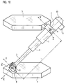
- Such telescopic arms are known per se and are, for example, in Hexapod machines ( Figure 10) are used, in which two platforms 5, 6 can be moved relative to each other via several telescopic arms.
- the principle a hexapod machine is shown in FIG.
- the construction of a hexapod machine is special easy if the first telescopic part 1 via a universal joint 7 in two degrees of freedom of movement, but torsionally rigid around the longitudinal axis X.
- Cardan joints 7, 8 are shown only schematically in FIG.
- the two telescopic parts 1, 2 are each via the universal joints 7, 8 to the first axis Y and rotatable about the second axis Z on the platforms 5, 6 stored. Both axes Y and Z run perpendicular to each other and Z runs perpendicular to the longitudinal axis X of the telescopic arm.
- the platform 5 is relative, for example, by six such telescopic arms moved to platform 6. With these movements there can also be a twist of a telescopic part 1 relative to the other telescopic part 2 around Longitudinal axis X take place. This twist is used in the example of three telescopic parts 1, 2, 3 through the rotatable mounting of both telescopic parts 1, 2 on the middle, driven by a motor 9 and the spline 4 Telescopic part 3 allows.
- the length measuring device is installed in the cavity of the telescopic arm, the installation space is thus due to the diameter of the telescopic parts 1, 2, 3 limited.
- As mounting surfaces for fastening the length measuring device are the inner cylindrical surfaces of the telescopic parts 1, 2 and the outer End faces available.
- the length measuring device consists of a scale 10 made of glass or Glass ceramic with a rectangular cross section. On one level An incremental graduation 11 is applied to the surface of the scale 10, which is photoelectric by means of a scanning device 20 in a manner known per se is scanned.
- the division 11 consists of alternately reflecting and non-reflective areas from a light source of the scanner 20 are illuminated. Those reflected by the division 11 Beams of light are emitted by photodetectors of the scanning device 20 detected and generated position-dependent electrical scanning signals therefrom are fed to an evaluation device in which the current distance L is determined.
- the scale 10 is attached to a scale support 12.
- the scale 10 with the scale support 12 rigid that is in Measuring direction X fixed immovably.
- the yardstick 10 elastic over an adhesive layer or a viscous liquid film (e.g. oil) on the scale support 12 and translationally movable and thus decoupled from the scale carrier 12.
- a hardening adhesive can be used become.
- Another possibility is that the center of the scale 10 with the measurement reference point A coincides, then the scale 10 can its entire length can be stored elastically on the scale support 12 since the measurement reference point inevitably sets in the middle of the scale 10.
- the scale support 12 is in the form of a fastening element Pivot bearing 13 attached to the outer end of the telescopic part 1.
- the pivot bearing 13 consists of an inner ring 14 on which the scale support 12 is rigid is attached and an outer ring 15 rotatable relative to the inner ring 14, the rigidly coupled to the telescopic part 1 and thus to the measuring reference point A, is screwed, for example.
- the pivot bearing 13 thus supports the scale carrier 12 at an end region C relative to the outer ring 15 in five degrees of freedom rigid and rotatable about the measuring axis X and largely free of play.
- the remaining area of the scale support 12 is translational (in the measuring direction X) movably supported.
- the scale carrier 12 is with the inner ring 14 of the Pivot bearing 13 rigidly connected in the end region C, for example screwed.
- the pivot bearing 13 and thus the end region C at a distance from the measurement reference point A. is arranged. So that the distance K does not measure the distance L. influenced negatively, it is advantageous if the portion of the scale carrier 12 between points C and A the same coefficient of thermal expansion has, like the connector from the outer ring 15 to the telescopic part 1 between points C and A. Due to temperature changes Changes in length caused between A and C are thus compensated.
- the coefficient of expansion of the scale 10 is almost 0 by the distance Measure as independently of temperature as possible between points A and B. to be able to.
- the rotatable unit consisting of the inner ring 14, the scale carrier 12 and the scale 10 is balanced to rotate around the Measuring axis X no undue torsional forces on the pivot bearing 13 and to exercise the scale 10.
- the area of the rotary bearing 13 is shown enlarged in FIG. 3 and in FIG 4 shows a section IV-IV of the pivot bearing 13 from FIG. 3.
- the pivot bearing 13 can be a ball bearing, roller bearing or needle bearing.
- the scanning device 20 is at the accessible end of the telescopic part 2 attached by means of a fastening element 21 via a coupling rod 23.
- the length of the coupling rod 23 from the fastener 21 to Scanning device 20 corresponds at least approximately to the required measuring length and thus the length of the scale 10.
- the coupling rod 23 is exclusive rigid in the area of the accessible end of the telescopic part 2 mounted on the telescopic part 2 and translational in the remaining area (in the measuring direction X) decoupled from the telescopic part 2.
- the coefficient of thermal expansion the coupling rod 23 is approximately 0 to measure the position to be able to perform independently of temperature changes.
- FIG. 5 shows the area of the scanning device 20 of the length measuring device shown enlarged.
- the scanning device 20 is per se known coupling 26 attached to the coupling rod 23.
- This clutch 26 is stiff in the measuring direction X and in directions transverse to it in small areas compliant. Rotations of the telescopic part 2 about the measuring axis X are from the coupling rod 23 via the coupling 26 to the scale carrier 12 and thus transferred to the scale 10.
- a guide 22 between the scanner 20 and the Scale 10 and / or the scale support 12 is provided.
- this guide is implemented as a roller guide with ball bearings 22.
- the ball bearings 22 are fastened to the scanning device 20.
- the one ball bearing 22 are supported laterally on scale 10 and other ball bearings 22 are based on the perpendicular to it, bearing the division 11 Surface.
- FIG. 1 shows a section VI-VI of Figure 1 in an enlarged view with the Guide part 27.
- the guide part 27 is a plastic rail, which in the Telescopic part 2 is pressed.
- the recess of the plastic rail 27 is adapted the contour of the scale 10 and / or the scale support 12 and forms a kind of sliding guide for the scale 10 to rotary movements to transfer the measuring axis X to the scale 10 and one to achieve vibration-stable construction.
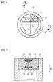
- FIGs 7 to 9 the fastener 21 for fastening the Scanning device 20 on the telescopic part 2 is shown enlarged.
- Figure 7 shows a cross section and
- Figure 8 is a plan view of the end of the telescopic arm 2.
- the scanning device is on this clamping ring 21 20 attached via the coupling rod 23.
- the clamping ring 21 is via an actuating element radially spread and on an inner cylinder surface 30 of the telescopic arm 2 radially clamped.
- the actuator can Be screw 31, which is axially accessible (X direction) and actuated, and two wedges 32, 33 moves in opposite directions. Heals 32, 33 are supported inclined surfaces of the clamping ring 21, causing an axial movement the wedges 32, 33 is converted into a radial movement, and thus one Widening of the slotted clamping ring 21 causes.
- FIG. 8 A section IX-IX of FIG. 8 is shown in FIG.
- the ring-shaped expansion element 21 has a slot 34.
- This slot 34 divides the expansion element 21 such that the outer diameter by the healing 32, 33 increases can be.
- the spreading is done by the two in the axial direction spaced wedges 32, 33 arranged in opposite directions, the opposite conical Have surfaces that are on corresponding surfaces support the expansion element 21.
- the two wedges 32, 33 are pulled together, causing the slot 34 enlarged.
- the function of the wedges 32, 33 can also be directly from the threads (Thread flanks) of a screw, not shown, are taken over, which is screwed into a thread of the expansion element running axially in the slot is and with the head on a surface of the expansion element supports.
- the expansion element can also be a rigid ring body be rotatably mounted in the one or more eccentric screws are.
- the head of such an eccentric screw has an eccentric running circumferential surface, which by turning with the cylinder surface 30th comes into contact and a radial clamping force between the ring body and the telescopic part 2 causes.
- reference marks in particular absolutely coded reference marks can be applied.
- the scale can also only have an absolute coding.
- the guide rail 27 forms a sliding guide for the scale 10.
- the guide rail additionally a roller or roller bearing guide for friction-free storage of scale 10.
- the guide rail 27 can for example can also be replaced by a recirculating ball bearing guide.
- the length measuring device can also have a connection for compressed air.
- This connection 101 is only shown in Figure 1 and is in a cap 100 or alternatively provided on the telescopic part 2. Important is, that the compressed air inlet in the space of the scale 10, that is, in the measuring room located.
- an elastic seal 102 is additionally provided Separation of the room in which the scale 10 is located and the room, in which the drive 9 with the spline 4 is provided.
Landscapes
- Physics & Mathematics (AREA)
- General Physics & Mathematics (AREA)
- Length Measuring Devices With Unspecified Measuring Means (AREA)
- A Measuring Device Byusing Mechanical Method (AREA)
Applications Claiming Priority (2)
| Application Number | Priority Date | Filing Date | Title |
|---|---|---|---|
| DE19747356A DE19747356A1 (de) | 1997-10-27 | 1997-10-27 | Längenmeßeinrichtung und Maschine mit einer Längenmeßeinrichtung |
| DE19747356 | 1997-10-27 |
Publications (3)
| Publication Number | Publication Date |
|---|---|
| EP0911612A2 true EP0911612A2 (fr) | 1999-04-28 |
| EP0911612A3 EP0911612A3 (fr) | 2000-10-11 |
| EP0911612B1 EP0911612B1 (fr) | 2006-06-14 |
Family
ID=7846722
Family Applications (1)
| Application Number | Title | Priority Date | Filing Date |
|---|---|---|---|
| EP98119002A Expired - Lifetime EP0911612B1 (fr) | 1997-10-27 | 1998-10-08 | Dispositif de mesure de longueurs et machine pourvue de ce dispositif |
Country Status (4)
| Country | Link |
|---|---|
| US (1) | US6272766B1 (fr) |
| EP (1) | EP0911612B1 (fr) |
| AT (1) | ATE330207T1 (fr) |
| DE (2) | DE19747356A1 (fr) |
Cited By (1)
| Publication number | Priority date | Publication date | Assignee | Title |
|---|---|---|---|---|
| EP2207009A2 (fr) | 2006-06-16 | 2010-07-14 | Renishaw plc | Ensemble de pattes extensibles pour appareil de mesure de position |
Families Citing this family (7)
| Publication number | Priority date | Publication date | Assignee | Title |
|---|---|---|---|---|
| US6587802B1 (en) * | 1998-09-17 | 2003-07-01 | Dr. Johannes Heidenhain Gmbh | Calibration device for a parallel kinematic manipulator |
| DE19943729A1 (de) * | 1999-09-03 | 2001-03-08 | Heidenhain Gmbh Dr Johannes | Wegmeßsystem |
| GB0023289D0 (en) * | 2000-09-22 | 2000-11-08 | Renishaw Plc | Determination of displacement |
| JP4869505B2 (ja) * | 2001-06-27 | 2012-02-08 | 株式会社ミツトヨ | エンコーダの摺動機構 |
| JP4031375B2 (ja) * | 2003-01-24 | 2008-01-09 | 株式会社ミツトヨ | 測定機 |
| US6860029B2 (en) * | 2003-06-17 | 2005-03-01 | George C. Haynes | Length adjustable tool for aligning boring bar |
| DE102008043353A1 (de) * | 2008-10-31 | 2010-05-06 | Dr. Johannes Heidenhain Gmbh | Längenmesseinrichtung |
Family Cites Families (6)
| Publication number | Priority date | Publication date | Assignee | Title |
|---|---|---|---|---|
| DE2505587C3 (de) * | 1975-02-11 | 1980-10-09 | Dr. Johannes Heidenhain Gmbh, 8225 Traunreut | Längenmeßeinrichtung |
| DE3113962C2 (de) | 1981-04-07 | 1987-04-02 | Dr. Johannes Heidenhain Gmbh, 8225 Traunreut | Längenmeßeinrichtung |
| US4988244A (en) | 1989-09-01 | 1991-01-29 | Kearney & Trecker | Six-axis machine tool |
| US5028180A (en) * | 1989-09-01 | 1991-07-02 | Sheldon Paul C | Six-axis machine tool |
| DE19629585C2 (de) | 1995-09-06 | 1998-12-10 | Heidenhain Gmbh Dr Johannes | Winkelmeßeinrichtung |
| ATE262161T1 (de) | 1995-09-06 | 2004-04-15 | Heidenhain Gmbh Dr Johannes | Winkelmesseinrichtung |
-
1997
- 1997-10-27 DE DE19747356A patent/DE19747356A1/de not_active Withdrawn
-
1998
- 1998-10-08 DE DE59813595T patent/DE59813595D1/de not_active Expired - Lifetime
- 1998-10-08 AT AT98119002T patent/ATE330207T1/de not_active IP Right Cessation
- 1998-10-08 EP EP98119002A patent/EP0911612B1/fr not_active Expired - Lifetime
- 1998-10-23 US US09/178,214 patent/US6272766B1/en not_active Expired - Lifetime
Cited By (1)
| Publication number | Priority date | Publication date | Assignee | Title |
|---|---|---|---|---|
| EP2207009A2 (fr) | 2006-06-16 | 2010-07-14 | Renishaw plc | Ensemble de pattes extensibles pour appareil de mesure de position |
Also Published As
| Publication number | Publication date |
|---|---|
| DE59813595D1 (de) | 2006-07-27 |
| US6272766B1 (en) | 2001-08-14 |
| DE19747356A1 (de) | 1999-04-29 |
| EP0911612A3 (fr) | 2000-10-11 |
| EP0911612B1 (fr) | 2006-06-14 |
| ATE330207T1 (de) | 2006-07-15 |
Similar Documents
| Publication | Publication Date | Title |
|---|---|---|
| DE19629585C2 (de) | Winkelmeßeinrichtung | |
| EP1154241A1 (fr) | Dispositif de mesure d'angles | |
| EP0911612B1 (fr) | Dispositif de mesure de longueurs et machine pourvue de ce dispositif | |
| EP0841539B1 (fr) | Dispositif pour la mesure de position et procédé de montage d'un dispositif de lecture dans un tel dispositif pour la mesure de position | |
| DE19945099B4 (de) | Winkelmesseinrichtung und Verwendung dieser Winkelmesseinrichtung in einer Spindelanordnung | |
| EP0902256B1 (fr) | Dispositif pour mesurer des angles | |
| DE102013001829A1 (de) | Drehwinkel- und Torsionswinkelsensor | |
| EP1102964B1 (fr) | Procede et moyen de positionnement pour le montage d'un systeme de mesure de position | |
| DE19956833A1 (de) | Winkelmeßsystem | |
| DE19534063A1 (de) | Winkelmeßeinrichtung | |
| DE19816827A1 (de) | Vormontierte Winkelmeßvorrichtung | |
| EP0533973A1 (fr) | Dispositif pour mesurer des angles | |
| DE2906432B1 (de) | Koppeleinrichtung | |
| EP0762082A1 (fr) | Capteur de position angulaire | |
| EP3228993B1 (fr) | Dispositif de mesure de longueur | |
| DE10308440A1 (de) | Vorrichtung zum Messen des Drehwinkels | |
| DE10137014B4 (de) | Positionsmesseinrichtung | |
| DE19757116C2 (de) | Anordnung mit magnetischem Maßstab | |
| DE3634816A1 (de) | Messvorrichtung zur formmessung von zylindern | |
| DE10208608A1 (de) | Getriebe sowie mit diesem Getriebe ausgestatteter Drehgeber | |
| DE102023116942B4 (de) | Messvorrichtung | |
| DE10058657A1 (de) | Verfahren und Meßeinrichtung zur Bestimmung von Beugewinkeln an Gelenkwellen | |
| DE102004050834B4 (de) | Positionsmesseinrichtung | |
| DE102007059362A1 (de) | Sensoranordnung mit Positioniermodul | |
| EP0882236A1 (fr) | Dispositif de positionnement d'une sonde de mesure |
Legal Events
| Date | Code | Title | Description |
|---|---|---|---|
| PUAI | Public reference made under article 153(3) epc to a published international application that has entered the european phase |
Free format text: ORIGINAL CODE: 0009012 |
|
| AK | Designated contracting states |
Kind code of ref document: A2 Designated state(s): AT CH DE FR GB IT LI |
|
| AX | Request for extension of the european patent |
Free format text: AL;LT;LV;MK;RO;SI |
|
| PUAL | Search report despatched |
Free format text: ORIGINAL CODE: 0009013 |
|
| AK | Designated contracting states |
Kind code of ref document: A3 Designated state(s): AT BE CH CY DE DK ES FI FR GB GR IE IT LI LU MC NL PT SE |
|
| AX | Request for extension of the european patent |
Free format text: AL;LT;LV;MK;RO;SI |
|
| 17P | Request for examination filed |
Effective date: 20010411 |
|
| AKX | Designation fees paid |
Free format text: AT CH DE FR GB IT LI |
|
| GRAP | Despatch of communication of intention to grant a patent |
Free format text: ORIGINAL CODE: EPIDOSNIGR1 |
|
| GRAS | Grant fee paid |
Free format text: ORIGINAL CODE: EPIDOSNIGR3 |
|
| GRAA | (expected) grant |
Free format text: ORIGINAL CODE: 0009210 |
|
| AK | Designated contracting states |
Kind code of ref document: B1 Designated state(s): AT CH DE FR GB IT LI |
|
| PG25 | Lapsed in a contracting state [announced via postgrant information from national office to epo] |
Ref country code: IT Free format text: LAPSE BECAUSE OF FAILURE TO SUBMIT A TRANSLATION OF THE DESCRIPTION OR TO PAY THE FEE WITHIN THE PRE;WARNING: LAPSES OF ITALIAN PATENTS WITH EFFECTIVE DATE BEFORE 2007 MAY HAVE OCCURRED AT ANY TIME BEFORE 2007. THE CORRECT EFFECTIVE DATE MAY BE DIFFERENT FROM THE ONE RECORDED.SCRIBED TIME-LIMIT Effective date: 20060614 |
|
| REG | Reference to a national code |
Ref country code: GB Ref legal event code: FG4D Free format text: NOT ENGLISH |
|
| REG | Reference to a national code |
Ref country code: CH Ref legal event code: EP |
|
| GBT | Gb: translation of ep patent filed (gb section 77(6)(a)/1977) |
Effective date: 20060620 |
|
| REF | Corresponds to: |
Ref document number: 59813595 Country of ref document: DE Date of ref document: 20060727 Kind code of ref document: P |
|
| PG25 | Lapsed in a contracting state [announced via postgrant information from national office to epo] |
Ref country code: LI Free format text: LAPSE BECAUSE OF NON-PAYMENT OF DUE FEES Effective date: 20061031 Ref country code: CH Free format text: LAPSE BECAUSE OF NON-PAYMENT OF DUE FEES Effective date: 20061031 |
|
| PLBE | No opposition filed within time limit |
Free format text: ORIGINAL CODE: 0009261 |
|
| STAA | Information on the status of an ep patent application or granted ep patent |
Free format text: STATUS: NO OPPOSITION FILED WITHIN TIME LIMIT |
|
| EN | Fr: translation not filed | ||
| 26N | No opposition filed |
Effective date: 20070315 |
|
| REG | Reference to a national code |
Ref country code: CH Ref legal event code: PL |
|
| PG25 | Lapsed in a contracting state [announced via postgrant information from national office to epo] |
Ref country code: AT Free format text: LAPSE BECAUSE OF NON-PAYMENT OF DUE FEES Effective date: 20061008 |
|
| PG25 | Lapsed in a contracting state [announced via postgrant information from national office to epo] |
Ref country code: FR Free format text: LAPSE BECAUSE OF FAILURE TO SUBMIT A TRANSLATION OF THE DESCRIPTION OR TO PAY THE FEE WITHIN THE PRESCRIBED TIME-LIMIT Effective date: 20070309 |
|
| PG25 | Lapsed in a contracting state [announced via postgrant information from national office to epo] |
Ref country code: FR Free format text: LAPSE BECAUSE OF FAILURE TO SUBMIT A TRANSLATION OF THE DESCRIPTION OR TO PAY THE FEE WITHIN THE PRESCRIBED TIME-LIMIT Effective date: 20060614 |
|
| PGFP | Annual fee paid to national office [announced via postgrant information from national office to epo] |
Ref country code: GB Payment date: 20141021 Year of fee payment: 17 |
|
| PGFP | Annual fee paid to national office [announced via postgrant information from national office to epo] |
Ref country code: DE Payment date: 20151022 Year of fee payment: 18 |
|
| GBPC | Gb: european patent ceased through non-payment of renewal fee |
Effective date: 20151008 |
|
| PG25 | Lapsed in a contracting state [announced via postgrant information from national office to epo] |
Ref country code: GB Free format text: LAPSE BECAUSE OF NON-PAYMENT OF DUE FEES Effective date: 20151008 |
|
| REG | Reference to a national code |
Ref country code: DE Ref legal event code: R119 Ref document number: 59813595 Country of ref document: DE |
|
| PG25 | Lapsed in a contracting state [announced via postgrant information from national office to epo] |
Ref country code: DE Free format text: LAPSE BECAUSE OF NON-PAYMENT OF DUE FEES Effective date: 20170503 |