EP0911628A1 - Sensor zur Wassergehaltsbestimmung - Google Patents
Sensor zur Wassergehaltsbestimmung Download PDFInfo
- Publication number
- EP0911628A1 EP0911628A1 EP98117103A EP98117103A EP0911628A1 EP 0911628 A1 EP0911628 A1 EP 0911628A1 EP 98117103 A EP98117103 A EP 98117103A EP 98117103 A EP98117103 A EP 98117103A EP 0911628 A1 EP0911628 A1 EP 0911628A1
- Authority
- EP
- European Patent Office
- Prior art keywords
- capacitor electrodes
- water content
- soil
- wires
- sensor according
- Prior art date
- Legal status (The legal status is an assumption and is not a legal conclusion. Google has not performed a legal analysis and makes no representation as to the accuracy of the status listed.)
- Granted
Links
- XLYOFNOQVPJJNP-UHFFFAOYSA-N water Substances O XLYOFNOQVPJJNP-UHFFFAOYSA-N 0.000 title claims description 47
- 239000003990 capacitor Substances 0.000 claims abstract description 33
- 239000002689 soil Substances 0.000 claims description 39
- 239000004020 conductor Substances 0.000 claims description 14
- 239000011888 foil Substances 0.000 claims description 3
- 238000005259 measurement Methods 0.000 description 27
- 239000000523 sample Substances 0.000 description 22
- 238000000034 method Methods 0.000 description 13
- 230000008901 benefit Effects 0.000 description 7
- 239000000463 material Substances 0.000 description 6
- 238000011156 evaluation Methods 0.000 description 4
- 238000013461 design Methods 0.000 description 3
- 238000002955 isolation Methods 0.000 description 3
- 239000011148 porous material Substances 0.000 description 3
- 239000007787 solid Substances 0.000 description 3
- 238000013459 approach Methods 0.000 description 2
- 230000007423 decrease Effects 0.000 description 2
- 238000009826 distribution Methods 0.000 description 2
- 238000001035 drying Methods 0.000 description 2
- 238000003973 irrigation Methods 0.000 description 2
- 230000002262 irrigation Effects 0.000 description 2
- 238000001956 neutron scattering Methods 0.000 description 2
- 230000003287 optical effect Effects 0.000 description 2
- 230000009467 reduction Effects 0.000 description 2
- 238000002310 reflectometry Methods 0.000 description 2
- 239000004575 stone Substances 0.000 description 2
- 238000003860 storage Methods 0.000 description 2
- 230000002123 temporal effect Effects 0.000 description 2
- 241000237942 Conidae Species 0.000 description 1
- 241000196324 Embryophyta Species 0.000 description 1
- 239000004593 Epoxy Substances 0.000 description 1
- 241000208125 Nicotiana Species 0.000 description 1
- 235000002637 Nicotiana tabacum Nutrition 0.000 description 1
- 238000004458 analytical method Methods 0.000 description 1
- 230000004888 barrier function Effects 0.000 description 1
- 230000008859 change Effects 0.000 description 1
- 238000012512 characterization method Methods 0.000 description 1
- 238000005056 compaction Methods 0.000 description 1
- 238000012937 correction Methods 0.000 description 1
- 230000008878 coupling Effects 0.000 description 1
- 238000010168 coupling process Methods 0.000 description 1
- 238000005859 coupling reaction Methods 0.000 description 1
- 230000001419 dependent effect Effects 0.000 description 1
- 238000001514 detection method Methods 0.000 description 1
- 238000011161 development Methods 0.000 description 1
- 239000003989 dielectric material Substances 0.000 description 1
- 230000000694 effects Effects 0.000 description 1
- 230000007274 generation of a signal involved in cell-cell signaling Effects 0.000 description 1
- 239000011521 glass Substances 0.000 description 1
- 239000003292 glue Substances 0.000 description 1
- 230000001771 impaired effect Effects 0.000 description 1
- 238000012625 in-situ measurement Methods 0.000 description 1
- 238000003780 insertion Methods 0.000 description 1
- 230000037431 insertion Effects 0.000 description 1
- 230000007774 longterm Effects 0.000 description 1
- 238000004519 manufacturing process Methods 0.000 description 1
- 239000013307 optical fiber Substances 0.000 description 1
- 230000010363 phase shift Effects 0.000 description 1
- 238000000053 physical method Methods 0.000 description 1
- 230000008569 process Effects 0.000 description 1
- 238000012545 processing Methods 0.000 description 1
- 230000035945 sensitivity Effects 0.000 description 1
- 230000008054 signal transmission Effects 0.000 description 1
- 238000004856 soil analysis Methods 0.000 description 1
- 230000008961 swelling Effects 0.000 description 1
- 238000009736 wetting Methods 0.000 description 1
Images




Classifications
-
- G—PHYSICS
- G01—MEASURING; TESTING
- G01N—INVESTIGATING OR ANALYSING MATERIALS BY DETERMINING THEIR CHEMICAL OR PHYSICAL PROPERTIES
- G01N27/00—Investigating or analysing materials by the use of electric, electrochemical, or magnetic means
- G01N27/02—Investigating or analysing materials by the use of electric, electrochemical, or magnetic means by investigating impedance
- G01N27/22—Investigating or analysing materials by the use of electric, electrochemical, or magnetic means by investigating impedance by investigating capacitance
- G01N27/223—Investigating or analysing materials by the use of electric, electrochemical, or magnetic means by investigating impedance by investigating capacitance for determining moisture content, e.g. humidity
-
- G—PHYSICS
- G01—MEASURING; TESTING
- G01N—INVESTIGATING OR ANALYSING MATERIALS BY DETERMINING THEIR CHEMICAL OR PHYSICAL PROPERTIES
- G01N27/00—Investigating or analysing materials by the use of electric, electrochemical, or magnetic means
- G01N27/02—Investigating or analysing materials by the use of electric, electrochemical, or magnetic means by investigating impedance
- G01N27/22—Investigating or analysing materials by the use of electric, electrochemical, or magnetic means by investigating impedance by investigating capacitance
- G01N27/226—Construction of measuring vessels; Electrodes therefor
Definitions
- the invention relates to a sensor for determining water content according to the preamble of claim 1.
- a frequently used measurement option is to determine the capacitance of a capacitor that encloses the moist floor as a dielectric (de Plater 1955).
- the capacitance which indicates the water content, can be determined by the resonance frequency.
- TDR method time domain reflectometry
- the running time and reflection of a electrical pulse in a pair of lines is used (Topp et al. 1982, Dasberg & Dalton 1985).
- the term and the Reflection of the impulse are influenced by the dielectric, that surrounds the pair of conductors.
- smaller versions of the TDR probe are used (Amato & Ritchie 1995; Kelly et al. 1995).
- Plate capacitor and annular capacitor are for the Case used that samples are taken and placed in a measuring chamber be introduced (Wobschall 1978, Sarabandi & Li 1994). Cylindrical symmetry Arrangements corresponding to the coaxial cable are also used as rehearsal rooms (Fellner-Feldegg 1969, Topp et al. 1982).
- plate capacitors are used in different ways Arrangement (de Plater 1955, Dean et al. 1987)) and two or three parallel bars (Dasberg & Dalton 1985, Nadler & Lapid 1996) or annular or cylindrical arrangements (Campbell 1990, Ould Mohamed 1997) used in the ground can be pierced or put on (Brisco et al. 1992).
- the spatial resolution of the probes does not reach values below 1 cm.
- the smallest version of the TDR probes is made by Amatso & Ritchi (1995).
- Kelly et al. (1995) deal specifically with this problem and show that even with an increased bandwidth of Measuring equipment (20 GHz) could not achieve a better spatial resolution is. They prove that especially in dry soils the accuracy decreases due to the short run times. There this temporal resolution cannot easily be increased the spatial resolution for the TDR method is approximately 1 cm limited.
- the TDR probe in its typical application or the access pipes with a diameter of a few cm, to facilitate the flow of water along the probe and thus to falsify the measured soil water content in the different soil depths compared to the undisturbed situation (Topp et al 1982, Dean et al. 1997, Evett & Steiner 1995, Ould Mohamed 1997).
- the resonance frequency is determined and from that the relative volumetric water content due to calibration calculated.
- the phase shift additional information about the conductivity can be obtained (Campbell 1990, Smith & Mullins 1991). Further additional information, e.g. about the aggregate size would be an advantage.
- the water content in the soil changes continuously, also depending on it from the depth. That is why continuous measurements are advantageous.
- the probe should also last for several months be stable because long-term measurements are also necessary and because it takes some time for the floor to fill up with the Probe reaches its natural structure (Nadler & Lapid 1996). So the probe should not have to be changed too often.
- the object of the invention is a sensor of the e. G. Way of designing that it has a high spatial resolution with a simple structure owns.
- the frame opening has a size between 1 cm 2 and 25 cm 2 and there should be between 5 and 20 wire pairs.
- the frame is placed horizontally in the floor. Because in particular the water content between the wires affects the capacity, the effective measurement volume is flat and lies in the frame opening. If the wire diameter is smaller or at most is equal to twice the wire spacing, the water flow only slightly affected by the measurement volume. As well the evaporated water can escape upwards without hindrance.
- the space around the frame, on the other hand, where the water flow is disturbed does not contribute to the measurement because there is no water in it Frame material penetrates and the water in this area through Do not glue additional material near the wire is coming.
- the capacity of this electrode arrangement depends on the wire length and especially on the wire spacing. This is the measurement accuracy determined by the stability of the wire spacing. Around to increase this stability are the wires with a certain mechanical tension attached to the frame. The voltage must be so large that the wires are inhomogeneous in the Soil (aggregates of various sizes, stones) not from theirs Position to be moved.
- the tension of the wires can e.g. caused by that the frame during the attachment of the wires in one Vise is bent so that the corresponding length by 5% is shortened (see Fig. 1). After the wire fastening is finished the frame relaxes, so that the wires themselves are tensioned become.
- Fig. 1 is also advantageous because small changes in position of a wire have no influence on the Have capacity. E.g. due to an inhomogeneity in the soil Wire moved within the plane, then it approaches that neighboring wire of the other electrode so that the capacity is enlarged in this area. At the same time, he moves away from that other wire section of the same electrode so that in this Area the capacity is lowered. Although the distance dependency the capacity is not linear, there is some Compensation.
- the frame can be suitably through a perforated epoxy board be realized because the material has adequate flexural strength has and moreover with holes for the wires in precise Distance is provided.
- the electrodes of the grid can also be made by elastic leaf springs will be realized. They are so attached in the frame that its broad side is vertical and thus the water movement not hindered up and down.
- the advantage is that the capacitor area is significantly increased and the Measurements are more accurate and less prone to interference. Indeed the leaf spring width should not be greater than five times of distance.
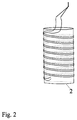
- the capacitor electrodes can also be in the form of two in parallel Wires can be realized that around a cylinder (see Fig. 2) or cones are wrapped or comb-shaped on the cylinder jacket are attached. With a suitable diameter, they can be introduced into boreholes and the water content in the area of the borehole.
- the cone has the advantage that the Contact between electrodes and floor is improved.
- the electrodes of the capacitor can also be connected by conductor tracks can be realized on double-sided printed circuit boards.
- Arrangements in Fig. 1 can also be a comb-shaped arrangement be (Fig. 3).
- the conductor tracks have the advantage that the conductors have a stable distance and that this distance compared to the wires in the frame on e.g. 0.4 mm reduced becomes. This reduces the dimensions of the entire probe.
- a disadvantage is that the board surface is solid and the above-mentioned faults can occur. Due to the small dimensions, this is largely meaningless if the boards are inserted vertically into the floor.
- a further miniaturization can be achieved if the Electrodes of the capacitor as well as the following electronic Circuit implemented in the form of an integrated circuit become.
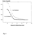
- the distance between the electrodes in FIGS. 1 and 2 determines the 4 shows the reduction in capacitance when the dielectric is removed from the wire plane with ⁇ > 1.
- the dielectric is the bottom of a glass vessel which is filled with water. In both cases, the wire spacing of 2 , 5 mm and 5 mm the capacity drops and you can see from the curve that the half width corresponds to about half the wire distance.
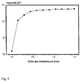
- FIG. 5 A stack of The dielectric forms an increasing number of identical PE foils with increasing thickness. In this case the dielectric constant comes the slides to wear. With increasing thickness the capacity increases.
- half-width is about half Corresponds to grid spacing.
- a narrow distance between the conductors thus reduces the Effective measurement volume thickness.
- the small thickness of the measuring volume allows a high resolution of the layers if you measure at different depths.
- the areal dimensions of 5 cm x 5 cm in FIG. 1 is advantageous, because the average is determined for certain levels.
- a punctual measurement would have the disadvantage that due to the aggregate structure of the soil measured at several points in a layer should be.
- the bottom is compacted at the edge of boreholes, so that the undisturbed water content cannot be measured.
- the electrode arrangement serves this purpose in Fig. 6.
- Conductors 1 and 2 are considered as the one capacitor electrode and conductor 3 as the other capacitor electrode, then is the effective electrode gap a. This is caused by that conductors 1 and 2 have the same potential and therefore no field can build up between them. But will in case B the conductors 1 and 3 are interconnected and form the first electrode and conductor 2 forms the other electrode, then the electrode spacing b is significantly smaller.
- the two measurements thus result in different measurement volumes recorded (see above), the measurement volume in case A essential is bigger.
- the difference (A-B) comes mainly the volume to carry, which is covered by A, but not by B.
- FIG. 6 If the arrangement of FIG. 6 is implemented on a film, can be attached to a cone or cylinder jacket, so the interference from the compaction at the edge of the borehole is prevented.
- the measurements are therefore mainly made with frequencies in the MHz and GHz range performed because then the conductivity of the soil no longer plays a role (H. Fellner-Feldegg 1969).
- the isolation of the electrodes has the advantage that the Influence of conductivity is also drastically reduced and that it becomes possible to at much lower frequencies measure that are easier to use.
- the electronic components cheaper and the circuit will less prone to interference because it becomes narrower. Furthermore there are no difficulties due to running times within the ladder on.
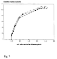
- volumetric Water content takes a form as shown in Fig. 7 is (4 series of measurements). The high initial slope of the curve shows that the arrangement is just for low values of soil water content has a high sensitivity.
- the capacitances of the capacitors 12, (see Fig. 8) with the given The electrode arrangement has a size of approximately 10 pF. It is therefore necessary to the capacitor without a long lead 13 to connect to the electronics, since cables also have a capacity between 0.3 and 3 pF / cm.
- the electronics for signal generation must also be used 3 in the ground and it is recommended to use one if possible simple arrangement to choose and for a safe signal transmission to care.
- 3 is therefore a digital signal generated, which preferably via an optical conductor 4 Evaluation electronics 6 is transmitted.
- the power supply from 3 takes place via lines 5 or via a battery in 3.
- the pulse generator 7 in FIG. 8b serves as the signal generator 3.
- the pulse length T m is accordingly determined by the capacitor 12 and the resistor 9 and the time between the pulses T d by the resistor 10 and the capacitor 11.
- T d can also transmit further information, for example the temperature, if resistor 10 is temperature-dependent is.
- the diode 8 converts the digital signal 8 into an optical signal, which can then be forwarded to the actual evaluation electronics via optical fibers without interference.
Landscapes
- Chemical & Material Sciences (AREA)
- Chemical Kinetics & Catalysis (AREA)
- Electrochemistry (AREA)
- Physics & Mathematics (AREA)
- Health & Medical Sciences (AREA)
- Life Sciences & Earth Sciences (AREA)
- Analytical Chemistry (AREA)
- Biochemistry (AREA)
- General Health & Medical Sciences (AREA)
- General Physics & Mathematics (AREA)
- Immunology (AREA)
- Pathology (AREA)
- Investigating Or Analyzing Materials By The Use Of Electric Means (AREA)
- Investigating Or Analyzing Materials By The Use Of Fluid Adsorption Or Reactions (AREA)
- Measurement Of Levels Of Liquids Or Fluent Solid Materials (AREA)
Abstract
Description

Claims (8)
- Sensor zur Wassergehaltsbestimmung bestehend aus mindestens zwei sich gegenüberliegenden Kondensatorelektroden mit Zuleitungen dadurch gekennzeichnet, daßa) die Länge der Kondensatorelektroden (1) mindestens zehnmal größer ist als die größte Querschnittsabmessung,b) der Abstand der Kondensatorelektroden (1) voneinander mindestens gleich der Querschnittsabmessung in Richtung ihres Abstandes ist, wobei die Dicke des Meßvolumens durch den Abstand der Kondensatorelektroden (1) eingestellt ist undc) die Kondensatorelektroden auf einer Fläche (2) angeordnet sind.
- Sensor nach Anspruch 1, dadurch gekennzeichnet, daß die Kondensatorelektroden (1) über einen Rahmen gespannte Drähte sind, wobei die Drähte ein Drahtgitter bilden und wobei die Drähte der beiden Kondensatorelektroden (1) sich in ihrer Reihenfolge abwechseln.
- Sensor nach Anspruch 1, dadurch gekennzeichnet, daß die Fläche (2) ein Kegel- oder Zylindermantel ist.
- Sensor nach Anspruch 1, dadurch gekennzeichnet, daß die Kondensatorelektroden (1) als Leiterbahnen auf einer Platine oder Folie realisiert sind.
- Sensor nach Anspruch 3 oder 4, dadurch gekennzeichnet, daß die Kondensatorelektroden (1) kammförmig oder mäanderförmig ausgebildet sind oder dass sie sich in ihrer Reihenfolge abwechseln.
- Sensor nach einem der Ansprüche 3, 4 oder 5, gekennzeichnet durch mindestens eine weitere Kondensatorelektrode (1) wodurch mindestens zwei Elektrodenabstände und damit zwei verschiedene Dicken des Meßvolumens realisiert sind.
- Sensor nach einem der Ansprüche 1 bis 6, dadurch gekennzeichnet, daß die Kondensatorelektroden (1) isoliert sind.
- Verwendung mindestens eines Sensors gemäß einem der Ansprüche 1 bis 7 zur Messung des Wassergehalts in Böden.
Applications Claiming Priority (2)
| Application Number | Priority Date | Filing Date | Title |
|---|---|---|---|
| DE19744784 | 1997-10-10 | ||
| DE19744784A DE19744784A1 (de) | 1997-10-10 | 1997-10-10 | Sensor zur Wassergehaltsbestimmung |
Publications (2)
| Publication Number | Publication Date |
|---|---|
| EP0911628A1 true EP0911628A1 (de) | 1999-04-28 |
| EP0911628B1 EP0911628B1 (de) | 2001-08-08 |
Family
ID=7845154
Family Applications (1)
| Application Number | Title | Priority Date | Filing Date |
|---|---|---|---|
| EP98117103A Expired - Lifetime EP0911628B1 (de) | 1997-10-10 | 1998-09-10 | Sensor zur Wassergehaltsbestimmung |
Country Status (3)
| Country | Link |
|---|---|
| EP (1) | EP0911628B1 (de) |
| AT (1) | ATE204081T1 (de) |
| DE (2) | DE19744784A1 (de) |
Cited By (2)
| Publication number | Priority date | Publication date | Assignee | Title |
|---|---|---|---|---|
| EP1607739A1 (de) * | 2004-06-18 | 2005-12-21 | Eidgenössiche Technische Hochschule Zürich | Kapazitiver Sensor |
| US8633047B2 (en) | 2011-09-02 | 2014-01-21 | Sensirion Ag | Method for manufacturing a sensor chip |
Families Citing this family (2)
| Publication number | Priority date | Publication date | Assignee | Title |
|---|---|---|---|---|
| DE10204347A1 (de) | 2002-02-01 | 2003-08-14 | Atmel Germany Gmbh | Verfahren zur Übertragung von Daten |
| DE102009011278B4 (de) * | 2009-03-05 | 2017-04-20 | Imko Micromodultechnik Gmbh | Sonde sowie Vorrichtung zur Ermittlung der Materialfeuchte oder Leitfähigkeit eines Mediums |
Citations (4)
| Publication number | Priority date | Publication date | Assignee | Title |
|---|---|---|---|---|
| US3424977A (en) * | 1966-05-04 | 1969-01-28 | Human Resources Foundation | Capacitive device responsive to water vapor content of a gas including insulated conductive wire electrodes forming a grid |
| US4502044A (en) * | 1982-05-19 | 1985-02-26 | Farris James R | Moisture alarm system |
| GB2256489A (en) * | 1991-05-31 | 1992-12-09 | Natural Environment Res | Capacitative measuring apparatus |
| EP0622628A2 (de) * | 1993-04-29 | 1994-11-02 | imko INTELLIGENTE MICROMODULE KÖHLER GmbH | Sonde für Materialfeuchtesensor |
Family Cites Families (3)
| Publication number | Priority date | Publication date | Assignee | Title |
|---|---|---|---|---|
| CH674085A5 (de) * | 1988-03-03 | 1990-04-30 | Martin Ineichen | |
| DE3911812C2 (de) * | 1989-04-11 | 1996-09-19 | Siemens Ag | Schneller Feuchtesensor auf Polymerbasis |
| DE4139356A1 (de) * | 1991-11-29 | 1993-06-03 | Armin Dr Brather | Platten-messkondensator |
-
1997
- 1997-10-10 DE DE19744784A patent/DE19744784A1/de not_active Ceased
-
1998
- 1998-09-10 AT AT98117103T patent/ATE204081T1/de active
- 1998-09-10 DE DE59801155T patent/DE59801155D1/de not_active Expired - Fee Related
- 1998-09-10 EP EP98117103A patent/EP0911628B1/de not_active Expired - Lifetime
Patent Citations (4)
| Publication number | Priority date | Publication date | Assignee | Title |
|---|---|---|---|---|
| US3424977A (en) * | 1966-05-04 | 1969-01-28 | Human Resources Foundation | Capacitive device responsive to water vapor content of a gas including insulated conductive wire electrodes forming a grid |
| US4502044A (en) * | 1982-05-19 | 1985-02-26 | Farris James R | Moisture alarm system |
| GB2256489A (en) * | 1991-05-31 | 1992-12-09 | Natural Environment Res | Capacitative measuring apparatus |
| EP0622628A2 (de) * | 1993-04-29 | 1994-11-02 | imko INTELLIGENTE MICROMODULE KÖHLER GmbH | Sonde für Materialfeuchtesensor |
Non-Patent Citations (3)
| Title |
|---|
| AMATO M ET AL: "Small spatial scale soil water content measurement with time-domain reflectometry", SOIL SCIENCE SOCIETY OF AMERICA JOURNAL, vol. 59, 1995, ISSN 0361-5995, pages 325 - 329, XP002091083 * |
| FROLOV G V ET AL: "A quasibalancing dielectric water-content meter for powdery building materials", MEASUREMENT TECHNIQUES, vol. 27, no. 5, May 1984 (1984-05-01), ISSN 0543-1972, pages 468 - 470, XP002091082 * |
| SHEIRETOV Y ET AL: "Dielectrometry measurements of spatial moisture profiles in oil-impregnated pressboard", PROCEEDINGS OF THE 4TH INTERNATIONAL CONFERENCE ON PROPERTIES AND APPLICATIONS OF DIELECTRIC MATERIALS (IEEE CAT. NO.94CH3311-8), vol. 2, 1994, ISBN 0-7803-1307-0, pages 701 - 704, XP000749804 * |
Cited By (4)
| Publication number | Priority date | Publication date | Assignee | Title |
|---|---|---|---|---|
| EP1607739A1 (de) * | 2004-06-18 | 2005-12-21 | Eidgenössiche Technische Hochschule Zürich | Kapazitiver Sensor |
| EP2278310A1 (de) * | 2004-06-18 | 2011-01-26 | Sensirion Holding AG | Kapazitiver Sensor |
| US8633047B2 (en) | 2011-09-02 | 2014-01-21 | Sensirion Ag | Method for manufacturing a sensor chip |
| US9140740B2 (en) | 2011-09-02 | 2015-09-22 | Sensirion Ag | Sensor chip and method for manufacturing a sensor chip |
Also Published As
| Publication number | Publication date |
|---|---|
| ATE204081T1 (de) | 2001-08-15 |
| DE19744784A1 (de) | 1999-05-06 |
| DE59801155D1 (de) | 2001-09-13 |
| EP0911628B1 (de) | 2001-08-08 |
Similar Documents
| Publication | Publication Date | Title |
|---|---|---|
| EP0995083B1 (de) | Kapazitiver füllstandssensor mit optimierter elektrodengeometrie | |
| EP2400275B1 (de) | Berührungslose füllstandsmessung von flüssigkeiten | |
| DE19629745C2 (de) | Vorrichtung sowie Verfahren zur Bestimmung von Bodeneigenschaften | |
| DE102006019178B4 (de) | Anordnung zur zweidimensionalen Messung von verschiedenen Komponenten im Querschnitt einer Mehrphasenströmung | |
| EP0926475A2 (de) | Kapazitiver Füllstandssensor mit integrierter Schmutzfilmdetektion | |
| EP0145861B1 (de) | Vorrichtung zum Messen von Drucken und zeitlichen Druckverläufen | |
| DE10256064B4 (de) | Verfahren und Vorrichtung zur Bestimmung des Wassergehalts und der Leitfähigkeit in Böden und Schüttgütern | |
| DE69837878T2 (de) | Gerät zur kapazitiven elektrischen detektion | |
| EP3821211A1 (de) | Vorrichtungen und verfahren zur kapazitiven schaumdetektion in flüssigkeitsbehältern | |
| EP3421950B1 (de) | Durchflusssensor, verfahren und durchflussmessgerät zur bestimmung von geschwindigkeiten von phasen eines mehrphasigen mediums | |
| DD271380A5 (de) | Reflektometrischer Feuchtigkeitsmesser für kapilarporöse Körper, insbesondere für den Boden | |
| DE10261138B4 (de) | Bodensensor und Verfahren zur Messung von Bodenparametern | |
| DE102014210122B4 (de) | Vorrichtung zum Bestimmen eines Werts einer zu messenden Eigenschaft eines Fluids, Verfahren zum Betreiben einer Vorrichtung zum Bestimmen eines Werts einer zu messenden Eigenschaft eines Fluids | |
| EP0389916B1 (de) | Messvorrichtung zur Bestimmung der dielektrischen Eigenschaften von Stoffen | |
| EP0911628B1 (de) | Sensor zur Wassergehaltsbestimmung | |
| EP0760467A1 (de) | Verfahren zur Bestimmung des Phasenteils eines Mediums in offenen und geschlossenen Leitungen | |
| EP0351700B1 (de) | Anordnung zur kapazitiven Füllstandsmessung | |
| EP0621466A1 (de) | Anordnung zur kapazitiven Füllstandsmessung und deren Verwendung | |
| EP0927877B1 (de) | Messvorrichtung für eine Kraftstoffanzeige | |
| DE4105445C2 (de) | Verfahren und Anordnung zum Messen von meteorologischen Größen mit Hilfe einer Radiosonde | |
| DE112006001212B4 (de) | Verfahren und Messgerät zur Messung von Wassergehalt | |
| DE1673046A1 (de) | Vorrichtung zur Messung der Bodenfeuchte | |
| DE102020003382B4 (de) | Feuchtemessvorrichtung mit antibakterieller Wirkung | |
| DE3402708C2 (de) | ||
| DE102018124501B3 (de) | Sensor zur Vermessung von Strömungsprofilen in großen Kolonnen und Apparaten |
Legal Events
| Date | Code | Title | Description |
|---|---|---|---|
| PUAI | Public reference made under article 153(3) epc to a published international application that has entered the european phase |
Free format text: ORIGINAL CODE: 0009012 |
|
| AK | Designated contracting states |
Kind code of ref document: A1 Designated state(s): AT BE CH DE DK FI FR GB IE IT LI NL SE |
|
| AX | Request for extension of the european patent |
Free format text: AL;LT;LV;MK;RO;SI |
|
| 17P | Request for examination filed |
Effective date: 19990617 |
|
| 17Q | First examination report despatched |
Effective date: 19991027 |
|
| AKX | Designation fees paid |
Free format text: AT BE CH DE DK FI FR GB IE IT LI |
|
| RBV | Designated contracting states (corrected) |
Designated state(s): AT BE CH DE DK FI FR GB IE IT LI NL SE |
|
| GRAG | Despatch of communication of intention to grant |
Free format text: ORIGINAL CODE: EPIDOS AGRA |
|
| GRAG | Despatch of communication of intention to grant |
Free format text: ORIGINAL CODE: EPIDOS AGRA |
|
| GRAH | Despatch of communication of intention to grant a patent |
Free format text: ORIGINAL CODE: EPIDOS IGRA |
|
| ITF | It: translation for a ep patent filed | ||
| GRAH | Despatch of communication of intention to grant a patent |
Free format text: ORIGINAL CODE: EPIDOS IGRA |
|
| GRAA | (expected) grant |
Free format text: ORIGINAL CODE: 0009210 |
|
| AK | Designated contracting states |
Kind code of ref document: B1 Designated state(s): AT BE CH DE DK FI FR GB IE IT LI NL SE |
|
| PG25 | Lapsed in a contracting state [announced via postgrant information from national office to epo] |
Ref country code: IE Free format text: LAPSE BECAUSE OF FAILURE TO SUBMIT A TRANSLATION OF THE DESCRIPTION OR TO PAY THE FEE WITHIN THE PRESCRIBED TIME-LIMIT Effective date: 20010808 Ref country code: FI Free format text: LAPSE BECAUSE OF FAILURE TO SUBMIT A TRANSLATION OF THE DESCRIPTION OR TO PAY THE FEE WITHIN THE PRESCRIBED TIME-LIMIT Effective date: 20010808 |
|
| REF | Corresponds to: |
Ref document number: 204081 Country of ref document: AT Date of ref document: 20010815 Kind code of ref document: T |
|
| REG | Reference to a national code |
Ref country code: CH Ref legal event code: EP |
|
| REG | Reference to a national code |
Ref country code: CH Ref legal event code: NV Representative=s name: ROTTMANN, ZIMMERMANN + PARTNER AG |
|
| REG | Reference to a national code |
Ref country code: IE Ref legal event code: FG4D Free format text: GERMAN |
|
| PG25 | Lapsed in a contracting state [announced via postgrant information from national office to epo] |
Ref country code: AT Free format text: LAPSE BECAUSE OF NON-PAYMENT OF DUE FEES Effective date: 20010910 |
|
| REF | Corresponds to: |
Ref document number: 59801155 Country of ref document: DE Date of ref document: 20010913 |
|
| PG25 | Lapsed in a contracting state [announced via postgrant information from national office to epo] |
Ref country code: BE Free format text: LAPSE BECAUSE OF NON-PAYMENT OF DUE FEES Effective date: 20010930 |
|
| PG25 | Lapsed in a contracting state [announced via postgrant information from national office to epo] |
Ref country code: SE Free format text: LAPSE BECAUSE OF FAILURE TO SUBMIT A TRANSLATION OF THE DESCRIPTION OR TO PAY THE FEE WITHIN THE PRESCRIBED TIME-LIMIT Effective date: 20011108 Ref country code: DK Free format text: LAPSE BECAUSE OF FAILURE TO SUBMIT A TRANSLATION OF THE DESCRIPTION OR TO PAY THE FEE WITHIN THE PRESCRIBED TIME-LIMIT Effective date: 20011108 |
|
| GBT | Gb: translation of ep patent filed (gb section 77(6)(a)/1977) |
Effective date: 20011106 |
|
| ET | Fr: translation filed | ||
| REG | Reference to a national code |
Ref country code: GB Ref legal event code: IF02 |
|
| BERE | Be: lapsed |
Owner name: GSF-FORSCHUNGSZENTRUM FUR UMWELT UND GESUNDHEIT G Effective date: 20010930 |
|
| PLBE | No opposition filed within time limit |
Free format text: ORIGINAL CODE: 0009261 |
|
| STAA | Information on the status of an ep patent application or granted ep patent |
Free format text: STATUS: NO OPPOSITION FILED WITHIN TIME LIMIT |
|
| 26N | No opposition filed | ||
| PGFP | Annual fee paid to national office [announced via postgrant information from national office to epo] |
Ref country code: CH Payment date: 20080828 Year of fee payment: 11 |
|
| PGFP | Annual fee paid to national office [announced via postgrant information from national office to epo] |
Ref country code: NL Payment date: 20080929 Year of fee payment: 11 Ref country code: IT Payment date: 20080827 Year of fee payment: 11 |
|
| PGFP | Annual fee paid to national office [announced via postgrant information from national office to epo] |
Ref country code: GB Payment date: 20080829 Year of fee payment: 11 |
|
| PGFP | Annual fee paid to national office [announced via postgrant information from national office to epo] |
Ref country code: DE Payment date: 20080820 Year of fee payment: 11 |
|
| PGFP | Annual fee paid to national office [announced via postgrant information from national office to epo] |
Ref country code: FR Payment date: 20080929 Year of fee payment: 11 |
|
| REG | Reference to a national code |
Ref country code: NL Ref legal event code: V1 Effective date: 20100401 |
|
| REG | Reference to a national code |
Ref country code: CH Ref legal event code: PL |
|
| GBPC | Gb: european patent ceased through non-payment of renewal fee |
Effective date: 20090910 |
|
| REG | Reference to a national code |
Ref country code: FR Ref legal event code: ST Effective date: 20100531 |
|
| PG25 | Lapsed in a contracting state [announced via postgrant information from national office to epo] |
Ref country code: NL Free format text: LAPSE BECAUSE OF NON-PAYMENT OF DUE FEES Effective date: 20100401 Ref country code: FR Free format text: LAPSE BECAUSE OF NON-PAYMENT OF DUE FEES Effective date: 20090930 Ref country code: DE Free format text: LAPSE BECAUSE OF NON-PAYMENT OF DUE FEES Effective date: 20100401 |
|
| PG25 | Lapsed in a contracting state [announced via postgrant information from national office to epo] |
Ref country code: LI Free format text: LAPSE BECAUSE OF NON-PAYMENT OF DUE FEES Effective date: 20090930 Ref country code: CH Free format text: LAPSE BECAUSE OF NON-PAYMENT OF DUE FEES Effective date: 20090930 |
|
| PG25 | Lapsed in a contracting state [announced via postgrant information from national office to epo] |
Ref country code: GB Free format text: LAPSE BECAUSE OF NON-PAYMENT OF DUE FEES Effective date: 20090910 |
|
| PG25 | Lapsed in a contracting state [announced via postgrant information from national office to epo] |
Ref country code: IT Free format text: LAPSE BECAUSE OF NON-PAYMENT OF DUE FEES Effective date: 20090910 |