EP0912073A2 - Dispositif pour le diagnostique et le traitement de troubles auditifs - Google Patents
Dispositif pour le diagnostique et le traitement de troubles auditifs Download PDFInfo
- Publication number
- EP0912073A2 EP0912073A2 EP98119499A EP98119499A EP0912073A2 EP 0912073 A2 EP0912073 A2 EP 0912073A2 EP 98119499 A EP98119499 A EP 98119499A EP 98119499 A EP98119499 A EP 98119499A EP 0912073 A2 EP0912073 A2 EP 0912073A2
- Authority
- EP
- European Patent Office
- Prior art keywords
- transducer
- mass
- range
- inertial mass
- ceramic tube
- Prior art date
- Legal status (The legal status is an assumption and is not a legal conclusion. Google has not performed a legal analysis and makes no representation as to the accuracy of the status listed.)
- Withdrawn
Links
Images


Classifications
-
- H—ELECTRICITY
- H04—ELECTRIC COMMUNICATION TECHNIQUE
- H04R—LOUDSPEAKERS, MICROPHONES, GRAMOPHONE PICK-UPS OR LIKE ACOUSTIC ELECTROMECHANICAL TRANSDUCERS; ELECTRIC HEARING AIDS; PUBLIC ADDRESS SYSTEMS
- H04R25/00—Electric hearing aids
- H04R25/60—Mounting or interconnection of hearing aid parts, e.g. inside tips, housings or to ossicles
- H04R25/604—Mounting or interconnection of hearing aid parts, e.g. inside tips, housings or to ossicles of acoustic or vibrational transducers
- H04R25/606—Mounting or interconnection of hearing aid parts, e.g. inside tips, housings or to ossicles of acoustic or vibrational transducers acting directly on the eardrum, the ossicles or the skull, e.g. mastoid, tooth, maxillary or mandibular bone, or mechanically stimulating the cochlea, e.g. at the oval window
-
- Y—GENERAL TAGGING OF NEW TECHNOLOGICAL DEVELOPMENTS; GENERAL TAGGING OF CROSS-SECTIONAL TECHNOLOGIES SPANNING OVER SEVERAL SECTIONS OF THE IPC; TECHNICAL SUBJECTS COVERED BY FORMER USPC CROSS-REFERENCE ART COLLECTIONS [XRACs] AND DIGESTS
- Y10—TECHNICAL SUBJECTS COVERED BY FORMER USPC
- Y10S—TECHNICAL SUBJECTS COVERED BY FORMER USPC CROSS-REFERENCE ART COLLECTIONS [XRACs] AND DIGESTS
- Y10S977/00—Nanotechnology
- Y10S977/70—Nanostructure
- Y10S977/831—Of specified ceramic or electrically insulating compositions
Definitions
- This invention relates to a device for diagnosing and treating hearing disorders. More particularly, the invention relates to a device for delivering auditory sensations to the profoundly deaf and others.
- the device is particularly suitable for supersonic bone conduction hearing devices, diagnosis and treatment of tinnitus, diagnosis and treatment of vestibular function conditions, echo location, and determination of individual sensitivity to ultrasonic signals.
- the ultrasonic frequency range is about 20 kHz to about 108 kHz or higher.
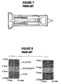
- the ceramic in response to the same electric field, the ceramic also expands or shrinks in the lateral direction, perpendicular to the electric field. However, since the physical size of the ceramic is constrained by virtue of its lamination to the aluminum sheet, the ceramic will bow the lamination into an either concave or convex form, depending on the polarity. Application of an alternating voltage will then generate vibrations at the frequency of the input signal.
- the devices of Figure 3 did not have a strong natural resonance in the 20 to 40 kHz region as required for supersonic hearing devices, nor did they have the required band width. Further, under the drive conditions required for supersonic hearing devices, these devices very rapidly either delaminated, broke the ceramic, broke the electrical connections to the ceramic electrodes, or heated up and depolarized rendering the ceramic inert.
- the invention provides a transducer which has a resonant frequency in the supersonic range.
- a tuning circuit can be used to increase the band width at resonance.
- the transducer is particularly suitable for use in supersonic bone conduction hearing devices, diagnosis and treatment of tinnitus, echo location, diagnosis and treatment of vestibular function conditions, and other applications and procedures which use supersonic signals.
- the transducer includes a piezoelectric ceramic tube which is compressed between a head mass and an inertial mass.
- a tensioning rod extends between the masses and is threadedly engaged with a nut which tensions the rod to adjust the compression on the ceramic tube.
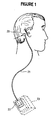
- Figure 1 illustrates a supersonic hearing assist device which includes a transducer 20, a cable 21, and a tuning circuit 22 which is mounted within an electronic housing 23.
- the transducer is held up against the mastoid process of the temporal bone.
- the transducer can also be applied to other surfaces of the human body, for example, the wall of the ear canal, the middle of the human forehead, the human tooth, human clavicle, human spine, or other bones.
- the housing 23 includes a microphone for receiving sounds in the auditory frequency range and a device for amplifying and converting the frequencies to the supersonic range and for applying electrical signals to the transducer.
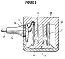
- the transducer 20 is best described as a piezoelectric longitudinal vibrator and includes a central piezoelectric ceramic tube 25, a radiating surface or head mass 26, and an inertial or tail mass 27.
- the radiating surface and inertial mass are tied together by a tensioning rod 28 to keep the assembly from self destructing as a result of large displacements of the radiating surface.
- the inertial mass is also the housing assembly for the device.
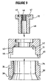
- the inertial mass 27 can be formed from separate components which include a generally cylindrical housing 30, a back plate 31, and a nut 32.
- the housing 30 represents the front half of the transducer inertial mass or housing assembly. It includes an outer wall with a recess 34 for mating with the back plate 31. One side is provided with a half capture ring 35 for clamping onto the cable strain relief 36 ( Figure 2). At this point, the inside diameter of the housing is carved out to provide a channel for transducer wiring 37 and 38 ( Figure 2). On the outer front surface, the housing features a retention ring 39 for a silicone rubber cap 40 ( Figure 2) on the transducer face. On the inner front diameter, the housing wall is tapered outward to allow for the taper on the head mass 26 ( Figure 2).
- the back plate 31 features an internal slotted ring 42 for the capture and adhesion of the piezoelectric ceramic tube 25 ( Figure 2).
- the electrical lead 37 for the inner electrode of the ceramic tube is passed through this hole around the bottom of the ceramic to the inner electrode.
- On this same side of the back plate there is a matching hole 44 for the cable and strain relief 36 ( Figure 2).
- the inner wall of the back plate is further recessed in this area to allow for the placement of the electrical leads 37 and 38 ( Figure 2) to the inner and outer cylindrical electrodes of the ceramic tube.
- the front of the back plate features an inner wall cut back 45 to provide for a cylindrical lap joint with the housing.
- the nut 32 comprises typically four complete 4-40 threads 46 to tension the tensioning rod 28 (Figure 2).
- Two holes 47 on the back surface of the nut allow for the pins of a spanner wrench to tighten the nut.
- the back walls of the nut and back plate 31 are in the same plane.
- the nut also features an inner column 48 of metal, with an outer diameter to fit inside the ceramic tube 25 (Figure 2) and an inner diameter to not interfere with the tensioning rod 28 ( Figure 2).
- the length of this column is designed to be as long as possible without interfering with the radiating surface or head mass 26.
- the entire housing assembly is designed for the maximum volume of metal to achieve the greatest inertial mass. If the radiating mass and the inertial mass have the same mass, then the acoustic radiation will be divided equally between the front and back surfaces. As more mass is accumulated in the tail mass, a greater fraction of displacement will occur at the head mass. For a tail mass to head mass ratio of 10:1, for example, the emission from the tail mass is 20 dB down from the emission from the head mass. The emission ratio is thus in competition with the physical size of the device.
- the material of the housing assembly is selected to be a hardened stainless steel, typically a 416 stainless steel hardened to Rockwell 35, to assure for minimal distortion of the transducer assembly. Any distortion of the housing assembly will be converted to heat, in addition to reducing the effective head mass emission.
- the overall physical size of the housing assembly is typically 0.75 inches in diameter, and 0.72 inches in length.
- the nominal mass of the collective housing assembly is typically 26 grams.
- the housing 30 and back plate 31 are typically bonded with a penetrating epoxy.
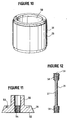
- the ceramic tube 25 ( Figure 2) for the transducer assembly, as illustrated in Figure 10, comprises a piezoelectric ceramic material with electrodes 50 and 51 on the inner and outer surfaces of the cylindrical wall, respectively. Both electrodes are etched back on both ends of the ceramic a small distance to allow for capture of the ceramic in the ceramic capture ring 42 of the back plate 31 and head mass 26 without resulting in a short circuit.
- the ceramic When a voltage is applied across the electrodes of the ceramic, the ceramic either expands or contracts in thickness. This motion is inconsequential to the operation of the device. At the same time, the ceramic also contracts or expands in length and circumference. The expansion and contraction in length is what drives the head mass in a longitudinal vibration.
- the ceramic material is selected from the family of lead zirconate titanate (PZT), more specifically from the PZT-4 and PZT-8 ceramics. These particular ceramic materials are selected for their especially low value of dissipation factor or loss tangent, the parameter which relates to the tendency of the ceramic to generate heat as a result of large applied electric fields. The low heat abilities of these materials markedly overshadow the attendant reduced displacement.
- PZT lead zirconate titanate
- the capacitances of typical ceramics are in the 7.5 nano Farad range.
- the ceramic tube 25 is bonded to the back plate 31 and to the head mass 26 with an epoxy, typically with a penetrating epoxy.
- the piezoelectric ceramic tube might be replaced in the electromechanical vibrator by a piezoelectric ceramic stack.
- the piezoelectric ceramic stack comprises a stack of ceramic washers of alternating piezoelectric polarity. Electrodes are wired in common, alternating along the length of the stack. The exchange of the ceramic stack for the ceramic tube will necessitate a minor redesign of the mating surfaces on the back plate and the head mass, the major difference being perhaps a greater wall thickness for the piezoelectric stack. This difference in wall thickness will affect the resonant frequency of the device.
- the radiating head mass 26 is depicted in cross section in Figure 11.
- the nominal diameter of the head mass is 0.50 inches.
- the head mass features a cylindrical groove 53 for ceramic retention, in the same manner as the back plate 31.
- the head mass also features at least four complete 4-40 threads 54 for the attachment of the tensioning rod 28 ( Figure 2).
- the face 55 of the head mass makes contact with the silicone cap 40 ( Figure 2). If the silicone cap material is clear, a fine machined surface is preferred.
- the head mass also features a cylindrical mass 55 of material extending toward the rear of the transducer, with an outer diameter less than the inner wall of the ceramic tube and an inner diameter which does not interfere with the tension rod. This extra material acts to stiffen the head mass and also to adjust the device resonant frequency.
- Head masses are in the mass range from typically 0.5 grams to 7 grams, more typically in the range from 1.5 to 4 grams. Ideally, the mass of the head mass would be approximately 10 times less than the mass of the housing assembly.
- the head mass is typically fabricated from common metals, more typically from hardened metals, and preferably from hardened stainless steel, typically 416 stainless steel hardened to Rockwell 35. Alternatively, brass may be used for increased mass (lower frequency) or aluminum for decreased mass (higher frequency).
- the tensioning rod 28 is depicted in Figure 12.
- the rod features a thinned middle section 57 and at least four complete 4-40 threads 58 on each end.
- One end additionally features a slot 59 for a small screw driver.
- the rod is adhesively bonded into the head mass 26 with a penetrating epoxy such that the face of the head mass and the flat end of the rod are flush.
- the slotted end 59 of the rod is attached to the nut 32.
- the screw driver slot allows for the tensioning of the rod by the nut without exerting a torque on the nut which might twist the rod or exert a rotational shear on the ceramic.
- the tensioning rod is typically fabricated from hardened stainless steel, typically 416 stainless steel hardened to Rockwell 35. A typical mass for the rod is 0.35 grams.
- the middle section 57 of the rod has a diameter at approximately 0.060 inches over a length of 0.49 inches.
- the transducer can be effectively operated without a cover over the head mass 26.
- a cap 40 ( Figure 2) is placed over the face of the transducer.
- This cap is typically from the family of materials referred to as silicone rubbers, more typically cast-in-place silicone rubber.
- a preferred material is a CF2-2186 silicone rubber manufactured by NuSil Technology, Inc.
- a silicone primer is typically used.
- a typical resonant frequency for the transducer with the above mentioned materials, dimensions, and masses is on the order of 28 kHz.
- the resonant frequency will go up.
- simply reducing the mass of the head mass will increase the resonant frequency of the device.
- the subject transducer has been implemented with different head masses ranging from 0.6 to 6.4 grams, with subsequent resonant frequencies from 22 to 39 kHz.
- the performance of the transducers is best assessed with the experimental configuration in Figure 13.
- a signal generator 61 is required to sweep a continuous wave signal across the band of operation of the transducer 20.
- the power amplifier 62 allows operation at any power level, to assess transducer response as a function of input level.
- the transducer is typically mounted in a vise, to best approximate the infinite inertial mass configuration.
- the transducer head mass is also fitted with a "water equivalent mass" 63 to compensate the measurements for the absence of the water (or tissue mass) medium which the transducer is designed to vibrate. The vibration of the head mass and the water equivalent mass is best measured with non-contacting optical displacement meter 64.
- the displacement of the head mass can be measured without the use of a water equivalent mass, in water, with a laser interferometer.
- the input signal to the transducer and the output of the calibrated displacement meter are passed to a scope 65 and/or spectrum analyser 66 which provides a hard copy output 67.
- the circuit also includes an attenuator 68.
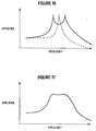
- a typical spectral response from a transducer using the above test method is illustrated in Figure 14, for a constant amplitude input signal.
- the spectrum typically features a low level flat response at low frequencies, typically within a few dB of the value predicted by Equation 1 above.
- the resonant frequency is typically predicted by Equation 3 above, and the resonant amplitude is typically 35 to 40 dB above the "DC" static level.
- the band width at typically 6dB down observed from an untuned transducer as seen in Figure 14 is unacceptable, typically in the 1 kHz range.
- the band width can be significantly enhanced by implementation of a tuning circuit.
- FIG. 15 depicts the equivalent circuit for the transducer with a tuning circuit.
- the system is operated in a push/pull mode (common mode).
- Each leg of the tuning circuit is identical.
- the piezoelectric ceramic and transducer components can be modeled as a parallel R, L, C, and C o circuit, where the L and C define the electromechanical resonant frequency of the transducer, the R reflects the sink for conversion of electrical energy to mechanical energy, and C o the clamped "DC" capacitance of the ceramic.
- the spectrum of Figure 14 is split into that depicted in Figure 16. If the inductive values are low, the resonance is at a higher frequency, and the higher frequency peak increases with respect to the lower frequency peak, and vice versa. While the band width is substantially increased, the remaining sharp spikes in the spectrum would result in too great a variation in amplitude for the human subject. Placing resistors across the inductors has the effect of lowering the spikes in the spectrum, to achieve the desired spectral response as depicted in Figure 17. Increasing the values of the resistors will increase the amplitude of the spikes in the spectrum while reducing the values of the resistors will round off the entire spectrum, and additionally will consume greater power from the electronic drive system.
- Parallel capacitors in the tuning circuit allow for fine tuning of the inductors to optimally match the tuned resonance with the device electromechanical resonance.
- the variation of the two peaks can typically be held to less than 2dB while the peak to null amplitude difference at the top of the spectrum can be held to less than 3 dB. Band widths can easily exceed 6 kHz.
- the inductive values of the tuning circuit are typically 2.4 milli Henry and the resistances typically have values of 3000 ohms.
- the transducer cable 21 ( Figure 2) is typically a shielded twisted pair cable, with the twisted leads 37 and 38 providing common mode power to the transducer and the shield electrically connecting the transducer housing assembly and head mass to the system ground.
- variations in transducer frequency band can be achieved by changing the mass of the head mass 26. These variations will affect the value of the tuning inductor and resistor.
- the inductor values are directly predictable by the resonant frequency and the ceramic capacitance.
- the resistive values are generally in the range from 1000 ohms to 10,000 ohms, the value being selected in final test to achieve the requisite flatness across the top of the transducer spectrum.
- the tensioning rod 28 through the middle of the transducer must have sufficient tension such that the head mass 26 is under compressive bias at all times, for any amplitude of emission, for any frequency.
- Newton's equation predicts the force on a mass undergoing oscillations at a specific frequency at a certain amplitude.
- the mass comprises the total mass of the head mass plus one third of the masses of the ceramic and the rod.
- the frequency under consideration corresponds to the highest frequency peak of the transducer spectrum.
- the transducer can also be used in a supersonic bone conduction hearing aid as described in Lenhardt U.S. Patent No. 4,982,434, in the diagnosis and treatment of tinnitus as described in U.S. patent application entitled "Tinnitus Masking Using Ultrasonic Signals,” Serial No. 08/264,527, filed June 23, 1994, and in other procedures and applications which utilize ultrasonic signals.
- the invention can also be used to test a patient's vestibular function on the theory that if a patient cannot hear using the bone conduction device described herein, which we believe is mediated by the vestibular system, then there is a vestibular problem.
- the invention can also be used to treat vestibular function disorders say, for example, as a "vestibular masker" to lessen or alleviate motion sickness.
Landscapes
- Health & Medical Sciences (AREA)
- General Health & Medical Sciences (AREA)
- Otolaryngology (AREA)
- Neurosurgery (AREA)
- Physics & Mathematics (AREA)
- Engineering & Computer Science (AREA)
- Acoustics & Sound (AREA)
- Signal Processing (AREA)
- Apparatuses For Generation Of Mechanical Vibrations (AREA)
- Measurement Of The Respiration, Hearing Ability, Form, And Blood Characteristics Of Living Organisms (AREA)
Applications Claiming Priority (2)
| Application Number | Priority Date | Filing Date | Title |
|---|---|---|---|
| US08/957,189 US6068590A (en) | 1997-10-24 | 1997-10-24 | Device for diagnosing and treating hearing disorders |
| US957189 | 1997-10-24 |
Publications (1)
| Publication Number | Publication Date |
|---|---|
| EP0912073A2 true EP0912073A2 (fr) | 1999-04-28 |
Family
ID=25499197
Family Applications (1)
| Application Number | Title | Priority Date | Filing Date |
|---|---|---|---|
| EP98119499A Withdrawn EP0912073A2 (fr) | 1997-10-24 | 1998-10-15 | Dispositif pour le diagnostique et le traitement de troubles auditifs |
Country Status (4)
| Country | Link |
|---|---|
| US (1) | US6068590A (fr) |
| EP (1) | EP0912073A2 (fr) |
| JP (1) | JPH11262481A (fr) |
| CA (1) | CA2248666A1 (fr) |
Cited By (2)
| Publication number | Priority date | Publication date | Assignee | Title |
|---|---|---|---|---|
| WO2009121105A1 (fr) * | 2008-03-31 | 2009-10-08 | Cochlear Limited | Dispositif de conduction osseuse à perçage dirigé |
| WO2012064247A1 (fr) * | 2010-11-12 | 2012-05-18 | Osseofon Ab | Réseau pour la fabrication de transducteurs à conduction osseuse |
Families Citing this family (69)
| Publication number | Priority date | Publication date | Assignee | Title |
|---|---|---|---|---|
| US6394969B1 (en) * | 1998-10-14 | 2002-05-28 | Sound Techniques Systems Llc | Tinnitis masking and suppressor using pulsed ultrasound |
| DE19859171C2 (de) * | 1998-12-21 | 2000-11-09 | Implex Hear Tech Ag | Implantierbares Hörgerät mit Tinnitusmaskierer oder Noiser |
| US6372031B1 (en) * | 1999-08-03 | 2002-04-16 | Milliken & Company | Washable coloring compositions comprising low molecular-weight styrene-maleic anhydride copolymers |
| DE10041725B4 (de) * | 2000-08-25 | 2004-04-29 | Phonak Ag | Gerät zur elektromechanischen Stimulation und Prüfung des Gehörs |
| US7792089B2 (en) * | 2002-07-31 | 2010-09-07 | Cattron-Theimeg, Inc. | System and method for wireless remote control of locomotives |
| US20100069752A1 (en) * | 2002-12-06 | 2010-03-18 | Otosonics, Inc. | Ultrasonic detection of ear disorders |
| EP1578263B1 (fr) * | 2002-12-06 | 2012-07-25 | Electrosonics Medical Inc. | Detection ultrasonore de troubles auditifs |
| US7668325B2 (en) * | 2005-05-03 | 2010-02-23 | Earlens Corporation | Hearing system having an open chamber for housing components and reducing the occlusion effect |
| US7867160B2 (en) * | 2004-10-12 | 2011-01-11 | Earlens Corporation | Systems and methods for photo-mechanical hearing transduction |
| US8295523B2 (en) * | 2007-10-04 | 2012-10-23 | SoundBeam LLC | Energy delivery and microphone placement methods for improved comfort in an open canal hearing aid |
| US8014871B2 (en) * | 2006-01-09 | 2011-09-06 | Cochlear Limited | Implantable interferometer microphone |
| US20070261494A1 (en) * | 2006-04-28 | 2007-11-15 | Biomec, Inc. | Ultrasonic transducer devices and detection apparatus |
| US7801319B2 (en) | 2006-05-30 | 2010-09-21 | Sonitus Medical, Inc. | Methods and apparatus for processing audio signals |
| US8291912B2 (en) * | 2006-08-22 | 2012-10-23 | Sonitus Medical, Inc. | Systems for manufacturing oral-based hearing aid appliances |
| HUE043135T2 (hu) * | 2006-09-08 | 2019-07-29 | Soundmed Llc | Fülzúgás kezelésére szolgáló módszerek és készülékek |
| US8270638B2 (en) * | 2007-05-29 | 2012-09-18 | Sonitus Medical, Inc. | Systems and methods to provide communication, positioning and monitoring of user status |
| US20080304677A1 (en) * | 2007-06-08 | 2008-12-11 | Sonitus Medical Inc. | System and method for noise cancellation with motion tracking capability |
| US20090028352A1 (en) * | 2007-07-24 | 2009-01-29 | Petroff Michael L | Signal process for the derivation of improved dtm dynamic tinnitus mitigation sound |
| US20120235632A9 (en) * | 2007-08-20 | 2012-09-20 | Sonitus Medical, Inc. | Intra-oral charging systems and methods |
| US8433080B2 (en) * | 2007-08-22 | 2013-04-30 | Sonitus Medical, Inc. | Bone conduction hearing device with open-ear microphone |
| US8224013B2 (en) | 2007-08-27 | 2012-07-17 | Sonitus Medical, Inc. | Headset systems and methods |
| US7682303B2 (en) | 2007-10-02 | 2010-03-23 | Sonitus Medical, Inc. | Methods and apparatus for transmitting vibrations |
| WO2009049320A1 (fr) | 2007-10-12 | 2009-04-16 | Earlens Corporation | Système et procédé multifonction pour une audition et une communication intégrées avec gestion de l'annulation du bruit et de la contre-réaction |
| US20090105523A1 (en) * | 2007-10-18 | 2009-04-23 | Sonitus Medical, Inc. | Systems and methods for compliance monitoring |
| US8795172B2 (en) * | 2007-12-07 | 2014-08-05 | Sonitus Medical, Inc. | Systems and methods to provide two-way communications |
| US7974845B2 (en) | 2008-02-15 | 2011-07-05 | Sonitus Medical, Inc. | Stuttering treatment methods and apparatus |
| US8270637B2 (en) | 2008-02-15 | 2012-09-18 | Sonitus Medical, Inc. | Headset systems and methods |
| US8023676B2 (en) | 2008-03-03 | 2011-09-20 | Sonitus Medical, Inc. | Systems and methods to provide communication and monitoring of user status |
| US20090226020A1 (en) * | 2008-03-04 | 2009-09-10 | Sonitus Medical, Inc. | Dental bone conduction hearing appliance |
| US8150075B2 (en) | 2008-03-04 | 2012-04-03 | Sonitus Medical, Inc. | Dental bone conduction hearing appliance |
| US20090270673A1 (en) * | 2008-04-25 | 2009-10-29 | Sonitus Medical, Inc. | Methods and systems for tinnitus treatment |
| WO2009155361A1 (fr) | 2008-06-17 | 2009-12-23 | Earlens Corporation | Dispositifs auditifs électro-mécaniques optiques présentant une architecture combinant puissance et signal |
| US8396239B2 (en) | 2008-06-17 | 2013-03-12 | Earlens Corporation | Optical electro-mechanical hearing devices with combined power and signal architectures |
| WO2009155358A1 (fr) | 2008-06-17 | 2009-12-23 | Earlens Corporation | Dispositifs d’audition électromécaniques optiques dotés de composants d’alimentation et de signal séparés |
| DK3509324T3 (da) | 2008-09-22 | 2023-10-02 | Earlens Corp | Balancerede armaturindretninger og fremgangsmåder til at høre |
| DK2438768T3 (en) | 2009-06-05 | 2016-06-06 | Earlens Corp | Optically coupled acoustically mellemøreimplantatindretning |
| US9544700B2 (en) | 2009-06-15 | 2017-01-10 | Earlens Corporation | Optically coupled active ossicular replacement prosthesis |
| CN102640435B (zh) | 2009-06-18 | 2016-11-16 | 伊尔莱茵斯公司 | 光学耦合的耳蜗植入系统及方法 |
| US8401214B2 (en) | 2009-06-18 | 2013-03-19 | Earlens Corporation | Eardrum implantable devices for hearing systems and methods |
| WO2011005479A2 (fr) | 2009-06-22 | 2011-01-13 | SoundBeam LLC | Systèmes et procédés de conduction osseuse à couplage optique |
| CN102598714A (zh) * | 2009-06-22 | 2012-07-18 | 音束有限责任公司 | 圆窗耦合的听力系统和方法 |
| WO2010151636A2 (fr) | 2009-06-24 | 2010-12-29 | SoundBeam LLC | Dispositifs et procédés de stimulation cochléaire optique |
| US8715154B2 (en) | 2009-06-24 | 2014-05-06 | Earlens Corporation | Optically coupled cochlear actuator systems and methods |
| US8433082B2 (en) | 2009-10-02 | 2013-04-30 | Sonitus Medical, Inc. | Intraoral appliance for sound transmission via bone conduction |
| WO2012088187A2 (fr) | 2010-12-20 | 2012-06-28 | SoundBeam LLC | Appareil auditif intra-auriculaire anatomiquement personnalisé |
| US20120300953A1 (en) * | 2011-05-24 | 2012-11-29 | Herbert Mauch | Integrity evaluation system in an implantable hearing prosthesis |
| WO2013062949A1 (fr) * | 2011-10-25 | 2013-05-02 | Martin Scientific, Llc | Réseau de capteurs et de télémesure de fond de trou à haut débit |
| CN103529565A (zh) * | 2013-10-22 | 2014-01-22 | 西安康弘新材料科技有限公司 | 压电陶瓷骨导振子在眼镜中的安装结构 |
| US10034103B2 (en) | 2014-03-18 | 2018-07-24 | Earlens Corporation | High fidelity and reduced feedback contact hearing apparatus and methods |
| EP3169396B1 (fr) | 2014-07-14 | 2021-04-21 | Earlens Corporation | Limitation de crête et polarisation coulissante pour dispositifs auditifs optiques |
| US20160089298A1 (en) | 2014-09-29 | 2016-03-31 | Otolith Sound Inc | Device for Mitigating Motion Sickness and Other Responses to Inconsistent Sensory Information |
| US9924276B2 (en) | 2014-11-26 | 2018-03-20 | Earlens Corporation | Adjustable venting for hearing instruments |
| US9999835B2 (en) * | 2015-02-05 | 2018-06-19 | Sony Interactive Entertainment Inc. | Motion sickness monitoring and application of supplemental sound to counteract sickness |
| EP3355801B1 (fr) | 2015-10-02 | 2021-05-19 | Earlens Corporation | Appareil intra-auriculaire personnalisé d'administration de médicament |
| US10306381B2 (en) | 2015-12-30 | 2019-05-28 | Earlens Corporation | Charging protocol for rechargable hearing systems |
| US10492010B2 (en) | 2015-12-30 | 2019-11-26 | Earlens Corporations | Damping in contact hearing systems |
| US11350226B2 (en) | 2015-12-30 | 2022-05-31 | Earlens Corporation | Charging protocol for rechargeable hearing systems |
| US10362415B2 (en) | 2016-04-29 | 2019-07-23 | Regents Of The University Of Minnesota | Ultrasonic hearing system and related methods |
| US20180077504A1 (en) | 2016-09-09 | 2018-03-15 | Earlens Corporation | Contact hearing systems, apparatus and methods |
| US11284205B2 (en) | 2016-11-14 | 2022-03-22 | Otolith Sound Inc. | Systems, devices, and methods for treating vestibular conditions |
| US20180133102A1 (en) * | 2016-11-14 | 2018-05-17 | Otolith Sound, Inc. | Devices And Methods For Reducing The Symptoms Of Maladies Of The Vestibular System |
| US10398897B2 (en) | 2016-11-14 | 2019-09-03 | Otolith Sound Inc. | Systems, devices, and methods for treating vestibular conditions |
| WO2018093733A1 (fr) | 2016-11-15 | 2018-05-24 | Earlens Corporation | Procédure d'impression améliorée |
| CN108245314A (zh) * | 2016-12-28 | 2018-07-06 | 中国科学院深圳先进技术研究院 | 用于进行听觉恢复治疗的超声波的生成装置 |
| US10631103B2 (en) * | 2017-05-30 | 2020-04-21 | Regents Of The University Of Minnesota | System and method for multiplexed ultrasound hearing |
| WO2019173470A1 (fr) | 2018-03-07 | 2019-09-12 | Earlens Corporation | Dispositif auditif de contact et matériaux de structure de rétention |
| WO2019199680A1 (fr) | 2018-04-09 | 2019-10-17 | Earlens Corporation | Filtre dynamique |
| RU2769058C1 (ru) * | 2021-01-22 | 2022-03-28 | Автономная некоммерческая организация дополнительного профессионального образования «Институт слуха и речи» | Способ оценки эффективности слухопротезирования и подбора слуховых аппаратов |
| US20230310216A1 (en) * | 2022-03-31 | 2023-10-05 | St Oto Devices, Llc | Apparatus and methods for treating tinnitus |
Family Cites Families (1)
| Publication number | Priority date | Publication date | Assignee | Title |
|---|---|---|---|---|
| US4982434A (en) * | 1989-05-30 | 1991-01-01 | Center For Innovative Technology | Supersonic bone conduction hearing aid and method |
-
1997
- 1997-10-24 US US08/957,189 patent/US6068590A/en not_active Expired - Fee Related
-
1998
- 1998-10-14 CA CA002248666A patent/CA2248666A1/fr not_active Abandoned
- 1998-10-15 EP EP98119499A patent/EP0912073A2/fr not_active Withdrawn
- 1998-10-22 JP JP10340932A patent/JPH11262481A/ja active Pending
Cited By (3)
| Publication number | Priority date | Publication date | Assignee | Title |
|---|---|---|---|---|
| WO2009121105A1 (fr) * | 2008-03-31 | 2009-10-08 | Cochlear Limited | Dispositif de conduction osseuse à perçage dirigé |
| WO2012064247A1 (fr) * | 2010-11-12 | 2012-05-18 | Osseofon Ab | Réseau pour la fabrication de transducteurs à conduction osseuse |
| US9491551B2 (en) | 2010-11-12 | 2016-11-08 | Osseofon Ab | Network for bone conduction transducers |
Also Published As
| Publication number | Publication date |
|---|---|
| US6068590A (en) | 2000-05-30 |
| CA2248666A1 (fr) | 1999-04-24 |
| JPH11262481A (ja) | 1999-09-28 |
Similar Documents
| Publication | Publication Date | Title |
|---|---|---|
| US6068590A (en) | Device for diagnosing and treating hearing disorders | |
| US7822215B2 (en) | Bone-conduction hearing-aid transducer having improved frequency response | |
| US7285895B2 (en) | Ultrasonic medical device and method | |
| CN1326634C (zh) | 用于产生高压超声波脉冲的设备 | |
| JP5011126B2 (ja) | 聴覚インプラント | |
| JP2007251358A (ja) | 骨伝導スピーカ | |
| US11383271B2 (en) | Ultrasound transducer | |
| US6614143B2 (en) | Class V flextensional transducer with directional beam patterns | |
| US8460221B2 (en) | Ultra-sonic and vibratory treatment devices and methods | |
| US7615912B2 (en) | Acoustic transducer | |
| US5608692A (en) | Multi-layer polymer electroacoustic transducer assembly | |
| JP4314306B1 (ja) | 超音波振動子 | |
| US6822373B1 (en) | Broadband triple resonant transducer | |
| US20240381041A1 (en) | Piezoelectric actuator with slidable coupler | |
| Song et al. | Piezoelectric performance of continuous beam and narrow supported beam arrays for artificial basilar membranes | |
| Sanchez et al. | Flexible piezoelectric sensors for miniaturized sonomyography | |
| JPH1056690A (ja) | 超音波トランスデューサ | |
| Kuwano et al. | Developing a Frequency‐selective Piezoelectric Acoustic Sensor Sensitive to the Audible Frequency Range of Rodents | |
| JPH05309096A (ja) | 衝撃波発生源 | |
| Agarwal et al. | 1pb3-5 visualization of ultrasonic waves in piezoelectric materials | |
| JP2009077130A (ja) | 超音波振動子 | |
| KR20020038197A (ko) | 압전소자를 이용한 골도 보청기용 진동자 | |
| US20240181278A1 (en) | Apodizing backing structures for ultrasonic transducers and related methods | |
| Cerezo Sanchez et al. | Flexible Piezoelectric Sensors for Miniaturized Sonomyography | |
| HAYDARI et al. | Construction of a Rotary vibrator and its application in human tactile communication |
Legal Events
| Date | Code | Title | Description |
|---|---|---|---|
| PUAI | Public reference made under article 153(3) epc to a published international application that has entered the european phase |
Free format text: ORIGINAL CODE: 0009012 |
|
| AK | Designated contracting states |
Kind code of ref document: A2 Designated state(s): AT BE CH CY DE DK ES FI FR GB GR IE IT LI LU MC NL PT SE |
|
| AX | Request for extension of the european patent |
Free format text: AL;LT;LV;MK;RO;SI |
|
| STAA | Information on the status of an ep patent application or granted ep patent |
Free format text: STATUS: THE APPLICATION IS DEEMED TO BE WITHDRAWN |
|
| 18D | Application deemed to be withdrawn |
Effective date: 20010503 |