EP0912115B1 - Cravate variable, d'une seule piece, a usages multiples - Google Patents
Cravate variable, d'une seule piece, a usages multiples Download PDFInfo
- Publication number
- EP0912115B1 EP0912115B1 EP97932772A EP97932772A EP0912115B1 EP 0912115 B1 EP0912115 B1 EP 0912115B1 EP 97932772 A EP97932772 A EP 97932772A EP 97932772 A EP97932772 A EP 97932772A EP 0912115 B1 EP0912115 B1 EP 0912115B1
- Authority
- EP
- European Patent Office
- Prior art keywords
- multipurpose
- necktie
- foregoing
- neck
- tie
- Prior art date
- Legal status (The legal status is an assumption and is not a legal conclusion. Google has not performed a legal analysis and makes no representation as to the accuracy of the status listed.)
- Expired - Lifetime
Links
- 238000000034 method Methods 0.000 claims abstract description 13
- 239000004744 fabric Substances 0.000 claims description 80
- 239000000463 material Substances 0.000 claims description 50
- 230000001681 protective effect Effects 0.000 claims description 11
- 238000004904 shortening Methods 0.000 claims description 5
- 210000000085 cashmere Anatomy 0.000 claims description 3
- 230000002787 reinforcement Effects 0.000 claims description 3
- 238000006243 chemical reaction Methods 0.000 claims 1
- 230000008901 benefit Effects 0.000 abstract description 5
- 239000011230 binding agent Substances 0.000 description 91
- 230000027455 binding Effects 0.000 description 89
- 230000036961 partial effect Effects 0.000 description 89
- 239000010410 layer Substances 0.000 description 45
- 230000015572 biosynthetic process Effects 0.000 description 16
- 230000008859 change Effects 0.000 description 15
- 230000002349 favourable effect Effects 0.000 description 13
- 238000013461 design Methods 0.000 description 10
- 238000011161 development Methods 0.000 description 7
- 230000018109 developmental process Effects 0.000 description 7
- 239000000126 substance Substances 0.000 description 6
- 239000000654 additive Substances 0.000 description 5
- 230000000996 additive effect Effects 0.000 description 5
- 230000007704 transition Effects 0.000 description 5
- 239000011248 coating agent Substances 0.000 description 4
- 238000000576 coating method Methods 0.000 description 4
- 230000006378 damage Effects 0.000 description 4
- 230000000694 effects Effects 0.000 description 4
- 230000008569 process Effects 0.000 description 4
- 230000002829 reductive effect Effects 0.000 description 4
- 238000004140 cleaning Methods 0.000 description 3
- 238000009415 formwork Methods 0.000 description 3
- 238000004804 winding Methods 0.000 description 3
- 229920000742 Cotton Polymers 0.000 description 2
- PXHVJJICTQNCMI-UHFFFAOYSA-N Nickel Chemical compound [Ni] PXHVJJICTQNCMI-UHFFFAOYSA-N 0.000 description 2
- 208000027418 Wounds and injury Diseases 0.000 description 2
- 239000003795 chemical substances by application Substances 0.000 description 2
- 238000005520 cutting process Methods 0.000 description 2
- 208000014674 injury Diseases 0.000 description 2
- 238000004519 manufacturing process Methods 0.000 description 2
- 230000003287 optical effect Effects 0.000 description 2
- 229920000728 polyester Polymers 0.000 description 2
- 238000012545 processing Methods 0.000 description 2
- 238000009958 sewing Methods 0.000 description 2
- 238000012549 training Methods 0.000 description 2
- 238000009941 weaving Methods 0.000 description 2
- 239000002759 woven fabric Substances 0.000 description 2
- 230000037303 wrinkles Effects 0.000 description 2
- RYGMFSIKBFXOCR-UHFFFAOYSA-N Copper Chemical compound [Cu] RYGMFSIKBFXOCR-UHFFFAOYSA-N 0.000 description 1
- 206010012434 Dermatitis allergic Diseases 0.000 description 1
- 241001295925 Gegenes Species 0.000 description 1
- 238000005299 abrasion Methods 0.000 description 1
- 239000000853 adhesive Substances 0.000 description 1
- 230000001070 adhesive effect Effects 0.000 description 1
- 230000002411 adverse Effects 0.000 description 1
- 229910052802 copper Inorganic materials 0.000 description 1
- 239000010949 copper Substances 0.000 description 1
- 230000001419 dependent effect Effects 0.000 description 1
- 238000006073 displacement reaction Methods 0.000 description 1
- 238000009826 distribution Methods 0.000 description 1
- 230000003670 easy-to-clean Effects 0.000 description 1
- 239000011521 glass Substances 0.000 description 1
- 238000003780 insertion Methods 0.000 description 1
- 230000037431 insertion Effects 0.000 description 1
- 238000009413 insulation Methods 0.000 description 1
- 230000003993 interaction Effects 0.000 description 1
- 239000002184 metal Substances 0.000 description 1
- 229910052751 metal Inorganic materials 0.000 description 1
- 230000004048 modification Effects 0.000 description 1
- 238000012986 modification Methods 0.000 description 1
- 229910052759 nickel Inorganic materials 0.000 description 1
- 244000144985 peep Species 0.000 description 1
- 239000004033 plastic Substances 0.000 description 1
- 239000000843 powder Substances 0.000 description 1
- 238000003825 pressing Methods 0.000 description 1
- 239000011241 protective layer Substances 0.000 description 1
- 230000009467 reduction Effects 0.000 description 1
- 230000000717 retained effect Effects 0.000 description 1
- 238000000926 separation method Methods 0.000 description 1
- 125000006850 spacer group Chemical group 0.000 description 1
- 230000009870 specific binding Effects 0.000 description 1
- 230000008961 swelling Effects 0.000 description 1
- 230000008719 thickening Effects 0.000 description 1
- 230000009466 transformation Effects 0.000 description 1
- 238000011282 treatment Methods 0.000 description 1
- 238000010792 warming Methods 0.000 description 1
Images







Classifications
-
- A—HUMAN NECESSITIES
- A41—WEARING APPAREL
- A41D—OUTERWEAR; PROTECTIVE GARMENTS; ACCESSORIES
- A41D23/00—Scarves; Head-scarves; Neckerchiefs
-
- A—HUMAN NECESSITIES
- A41—WEARING APPAREL
- A41D—OUTERWEAR; PROTECTIVE GARMENTS; ACCESSORIES
- A41D25/00—Neckties
-
- A—HUMAN NECESSITIES
- A41—WEARING APPAREL
- A41D—OUTERWEAR; PROTECTIVE GARMENTS; ACCESSORIES
- A41D25/00—Neckties
- A41D25/06—Neckties with knot, bow or like tied by the user
Definitions
- the present invention relates to a multi-purpose binder with a neck part, a binding part and a front part.
- the binding part can to be knotted.
- Under a multipurpose truss is here also a tie or long tie, a neck tie or a kind of scarf to be understood, provided this is cut to length changes.
- Ties usually have a tie part, a neck part and a front part on, whereby there is no clear separation of these from each other got to.
- the binding part is preferably entwined to form a knot, that part of the front part with the protruding part of the neck part covers its free end.
- the decorative appearance of the tie will thus essentially through the choice of the tie fabric and the design of the front part.
- the design as well as the choice the tie fabric is not arbitrary. In the manufacture of The tie fabric cannot be embroidered or designed arbitrarily, e.g. made of lace. This would be a traditional one if necessary Do not support further processing of a tie fabric.
- the choice of the tie fabric is also limited by the fact that there are requirements arising from the use of a manufactured tie. These requirements include durability, robustness, Bandage quality, washability and / or ironability. Because of that, it is possible that the optical quality when choosing a tie fabric in can kick the background.
- Another limitation of a tie arises due to fashionable ideas for certain areas or occasions only different designs of a long tie allow. During festive occasions a rather subtle one Requiring a tie are especially in the leisure area Ties with colorful, sometimes also bright motifs preferred. Added to this over time, the taste of the Forming a tie. This change only sets a tie limited useful life. Ties are therefore known in which Items are interchangeable.
- DE 88 17 058 U1 shows a tie, in which at least the front part is interchangeable.
- EP 0 579 972 discloses a long tie, the length of which consists of several, to each other available individual parts. These items can be different Have motifs and / or patterns.
- DE 92 06 006 U1 discloses also a multi-piece tie, the front part of two from each other different, but interconnectable parts, whereby a non-visible glasses cleaning cloth can be hidden between them, while FR 73 37 114 shows a tie in which a front part in a neck part is insertable.
- DE 69 13 333 discloses a tie in the manner of a long tie with two layers of tie fabric. These each form a display area from, with both display areas on the edge of the tie partially together are connected. By opening one of the two display areas, the others exposed. Another type of multiple use is shown in the FR 25 93 680.
- the long tie shown there is used as a surprise tie referred to, since its front part is hinged and from the thus formed A fly can be removed from the room.
- a long tie which has two free ends has: one is the end of the front part, the other is the end of the Neck part of the long tie.
- both ends can do so be stacked on top of each other so that neither end is against each other can be moved.
- the narrower end of the neck part of a freely foldable partial rag overlaps the front part and on this attached. This is to prevent the narrower end of the neck part from Moving the front part becomes visible.
- the U.S. 4,613,992 shows a multi-purpose binder, the versatile one Long tie binding options: as a tie, for example as Ascot.
- the long tie is made from a neck tie part and an attached square made of fabric. The fabric of the square can be folded depending on the desired shape of the multi-purpose binder.
- the object of the present invention is to provide a further tie that is multi-purpose and has different configurations on its own Provides. Furthermore, it is an object of the invention to find a suitable one Procedure for taking advantage of the multi-purpose ability of the tie Inclusion of the different designs of the tie to create.
- Free-folding means that the two partial flaps do not pass through a seam is permanently fixed together. This makes it possible to Change the width of the section as required.
- the variable multi-purpose binder with a neck part, a binding part and a front part is still integrally formed.
- the variability ensures the Multi-purpose truss on its own.
- the freely repeatable foldability is hence an independent inventive idea that is also independent.
- the variability is further enhanced by an adjustment option the total length and / or the width preferably achieved in the neck part.
- the multi-purpose binder not only for festive matters, but also can also be used as a scarf or as a more casual cloth. So will for example, a multi-purpose tie with a length worn as a tie shortened from about 1.5m to about 1.1m total length if this multi-purpose truss is used as a scarf or scarf.
- the wrapping of the binding part is facilitated to to get a sufficiently wide and thick cloth knot.
- the wrapping of the binding part and formation of the Cloth knot is carried out so that a neck width by pulling the neck part is set.
- the use of the multi-purpose binder as a cloth is can be supported in that a region of the neck part widens repeatedly becomes.
- a particularly preferred embodiment of the invention further provides that the front part is free at least in a partial area from at least three foldable partial rag is constructed.
- the partial flaps can then be folded in to lie against each other or at least partially overlapping come. They can advantageously be connected to one another, with the addition being have suitable fasteners.
- the opening section of the front part is at least 25 cm, in particular at least 30 cm and preferably at least 35 cm is. This prevents wrinkling from occurring when the unfolded part used in an embodiment according to the invention is a kind of Ascot-like coverage of the advantageously in To form the binding part of the knot.
- a preferred embodiment of the multi-purpose binder provides that the Width of at least the portion of the front part is adjustable. It is favorable if the width of the partial area of the front part is one preset width corresponding to a multipurpose truss to that of one Cloth is foldable. In particular, efforts should be made to reduce the width by at least To increase 25%, preferably by more than 50% and in particular by more than 100%. Depending on the structure of the front part, whether two or there are more freely foldable partial rags, a corresponding one is distributed target maximum width on these different partial lobes.
- a particularly preferred embodiment of a multipurpose truss provides that the hinged section is at least 40 cm, advantageously the partial lobes to the end of the front part of the multipurpose truss are freely foldable. This ensures that regardless of where in the Tie part or in the front part of it twisted into a knot the Ascot-shaped form is always available of sufficient length to be inserted into a shirt.
- the neck part or a section of it points in no insert or lining on one version. That's the section not tubular, but foldable and so wide that the am Neck material to come, preferably silk, folded together with the outer fabric roughly the material thickness of the other multi-purpose binder Has. The folding and unfolding of this section is done on the one hand by a stretch effect of the fabric or fabrics used and the other supported by the cut.
- the tie fabric is preferably made from cut out the woven fabric so that these individual parts are offset by approximately 45 ° to the vertical of the weaving direction of the woven fabric.
- a further development of this configuration provides that the inner fabric, preferably silk, at the respective ends of the section with the Outer fabric is sewn, but then a free area of the inner fabric joins.
- This can advantageously be tubular Part of the neck part are inserted and in interaction with one other free area or the neck part a closure of the neck part enable by appropriate means.
- the front part can now be opened several times the binding part can be wrapped around the neck part.
- the multi-purpose binder is at least partially the length and / or the width of his in particular Neck part can be changed repeatedly.
- the following are more different Possibilities based on the particularly preferred modification of the neck part shown.
- One embodiment of a multipurpose truss has a V-shaped blank. This is located in an end area of a hinged area of the neck part.
- the V-shaped blank preferably also delimits this, so that the binding part or the front part is attached to this blank directly connects. If tension is now exerted on the neck part, this expands Material of the neck part, which is supported by the V-shaped cut becomes. This allows the neck part to be larger in the non-pull condition Has width than with train. There is an area to be changed in the neck part definable in that the neck part has two V-shaped cuts. These are then the limits of the changeable neck part. In addition to the Any other cut is also used with a V-shaped cut can be used, which ensures the repeatable changeability of the neck part.
- the opening of the neck part is also due to the type of arrangement the fabric orientation achievable.
- the Fabric orientation in the hinged area a different elasticity behavior, if the hinged area is around 30 ° to 60 °, in particular 45 ° twisted fabric orientation to another area of the multipurpose tie having.
- the elasticity behavior depends on the type of used Fabric and is targeted by changing the structure of the fabric adjustable.
- the area with a twisted fabric cut is with the adjacent areas firmly connected, for example by one or more Stitching.
- Stitching for example by one or more Stitching.
- One-piece of the variable multi-purpose truss secured One-piece in the sense of the invention is to be understood as that the neck part, the binding part and the front part are connected to each other are that they only separate from each other again by destroying the multipurpose truss can be separated.
- the multipurpose tie has a neck portion that fixed in length can be repeatedly shortened and extended again.
- the Fixation prevents, for example, the shortened length of the neck part changes involuntarily. This ensures that the variability of the multi-purpose truss, even with multiple changes over a long period Considered period, is retained.
- the neck part is adjustable adjustable. That means that Repeatable length change not from the start for the variable Multipurpose truss is set.
- An adjustable variability of the neck part is for example by means of a movable fixation or by sticking surfaces achievable.
- the fastening device can be a fixation, for example, as just discussed has been.
- the fastening device at least adjacent to a beginning of the changeable Neck area. This allows, for example, this changeable neck area in the event of a change in the neck part, or at least being able to cover it only partially exposed. Is the beginning of the changeable Neck area with the transition from the neck part to the binding part or the fastening device is at least adjacent to the binding part available, so the neck part can be shortened very far.
- a fastening device is at least adjacent to a bushing is available.
- Carrying can be a label, a loop or also, for example, an incision in the binding part or front part. The Incision can be made so that the neck part can be inserted into it so that it disappears in the multipurpose truss.
- the multi-purpose truss can not only be a fastening device, but also have several. This is the length and / or Width of the neck part can be changed and adjusted. There are fastening devices for this connectable with each other.
- a multipurpose truss is the fastening device at least partially with material, especially fabric, covered.
- Fastening devices can also be used in this way, have the edges.
- the cover prevents a person from being at the Handling the multi-purpose truss injured. This is particularly true in the important areas of the multipurpose tie.
- the material can be used as an elastic protective layer. Will in the A person's multipurpose tie forms a knot on the neck of the person tightened, the material prevents pressing and forming Press points through the fastening device located in the neck area.
- the cover allows the possible choice of materials for the Fastening device is very wide.
- the fastening device can also be used, around layers of fabric from which the neck part, the binding part or the front part exists to fixate with each other. To do this, the fastening device go all or part through all layers of fabric. But it can also be attached to a first layer of fabric and then the rest Fix layers of fabric.
- the fastening device is particularly so attachable, that it is hidden, that means that it is not visible. This can be in a fold of the multipurpose truss, but also as well through the material that covers the fastening device.
- a a further preferred embodiment has a gathering of the material adjacent to the fastening device. This has the effect that the fastening device is covered by the material at least at its edge, so that direct skin contact with at least the edge is avoided.
- Preferred fastening devices are spring heads or ball parts. This connected together, then result in a push button. Through this is the Change the length and / or width of the neck part to uncomplicated Can be manufactured and detached again.
- Other possible fastening devices are needles, adhesive surfaces, buttons with a corresponding counterpart, Grinding or the like.
- the binding part so long that with two to five, preferably three loops of the binding part with itself from it Knot is ready to tie.
- the binding part which is between the front part and the neck part, can be indicated by suitable markings.
- the binding part can have a different material than the neck part and the Front part.
- the fastening device Can be used to determine the area required for the formation of a node is available. Due to the length limitation of the binding part is then depending on the purpose of the multipurpose truss, always stipulates how much Material can be twisted in the knot. It depends on what for a knot and how thick it is.
- a further limitation of the binding part is by appropriate arrangement the implementation achievable. This is attached so that it is at a two to five times wrapping the binding part with itself, just in Knot disappears. Depending on how long the binding part and thus also the thickness of the knot to be formed is the implementation arranged at least adjacent to the front part. By additional arrangement a fastening device at least adjacent to the implementation if necessary, the neck part can also be fixed there.
- the front part is repeatable can be opened and closed.
- This repeatable opening and closing is through a appropriate training of the front part itself specified.
- the front part of the multipurpose tie has the Ability to unfold especially up to a tear protection Seam, especially a lock.
- the seam can still be in the Front part, but also in the binding part. It is used for tubular Merging one or more substances, then the corresponding one Form the front or tie part.
- the front part can also be designed that the seam only begins in the binding part.
- the tear protection, the destruction prevents the seam can then be used as a marking of this transition.
- the use a label is also possible. This then becomes permanent fastened around the seam.
- the multi-purpose capability of the multi-purpose binder continues to be supports if the front part and / or adjacent parts means for Have wrinkles. These funds are useful when the multi-purpose binder is used ascot or as a scarf. Such means are small knitted or inserted threads, shirring tape, one or more slits, especially in an insert that is located in the front part. When tying of the multi-purpose binder can be inserted into the slots in the insert, which then leads to wrinkling. This wrinkling then comes again of particular importance if the front part consists of two or more foldable partial rag is constructed. These are joined together especially sewn together. Preferred is a front part, which is three Has partial rag sewn together from three individual pieces.
- the front part can also include a deposit. This is between the inner layer and the fabric of the Front part can be arranged.
- the inner layer and / or the insert in the Front part can have these fasteners. This can be tabs, Loops, loops or Velcro.
- Corresponding the variability of the multipurpose tie shows an embodiment of the Multipurpose binder on an inner layer and / or insert, which from a Formwork consists. Cashmere, for example, is preferred as the formwork material suitable. Polyester, cotton, silk or the like can also be used, which have a corresponding processing for a scarf.
- the Inlay is preferably glued and sewn in the front part.
- the insert attached to the inner layer is the insert attached to the inner layer.
- the Multi-purpose truss as such with front part, binding part and neck part remains receive.
- a needle has proven to be particularly suitable for carrying out proven with a protective cap for a tip of the needle, which is also a represents an independent inventive idea. This needle is comparable to a safety pin or tie pin can be designed or accordingly a stitching pin.
- the important feature of the needle for the multi-purpose binder it is that the needle and / or the protective cap an additional means for Has attachment to the multipurpose tie. This can open the needle with one of the two parts remaining on the multipurpose truss. The other part, for example the needle itself, can then be held in the hand become.
- a multi-purpose multi-purpose binder with a neck part, a binding part and a front part points in a part of the multi-purpose truss, preferably the binding or front part, an opening, in particular a slot, from which an insert or Inner layer can be pulled out and then used as a cloth.
- the insert or inner layer is pulled out wider than the front part of the multi-purpose binder in the form of a long powder.
- the deposit is conveniently attached only near the slot so that it on the one hand can perform its function as an inlaid feed, on the other hand can be easily pulled out of the slot.
- the slot itself is advantageously not in one when wearing the multi-purpose binder visible area, so that when using the cloth in an ascot-like manner the multipurpose truss only needs to be turned over.
- a multi-purpose binder is also preferred a neck part, which provides for its own closure, for example by means of buttons and buttonholes or by means of push buttons or Velcro fastener.
- a cleanable, preferably Insert washable hose which then covers the closing area is pulled.
- This coating itself has an independent and inventive Idiosyncrasy. Furthermore, this coating has two slots through which at least part of the front part can be pulled through, in particular so that it forms a kind of stylized knot for the collar becomes.
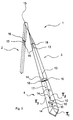
- FIG. 1 shows a one-part multipurpose binder 1 with a neck part 2, a binding part 3 and a front part 4.
- a partial region 5 of the front part 4 is constructed over a length 1 from three freely foldable partial flaps T 1 , T 2 and T 3 .
- the central partial flap T 1 has a further partial flap T 2 and T 3 on each side.
- Each of these, together with the partial flap T 1 has a preferred folding line 6, which is indicated by dashed lines.
- the neck part 2 and the binding part 3 are also held in a hinged manner, which is indicated by the dashed line 7.
- the fabric of the front part 4 is sewn twice from the tip, ie with a thin one Be provided with lining.
- the front part preferably has this double seam up to approximately two thirds in height from the tip 7. Furthermore, it is favorable that there is a seam reinforcement at least in the partial area 5 along an edge 8 of the front part 4. This provides the partial lobes with a certain stiffness and thus gives them additional stability.
- the edge regions are preferably folded down and these Then seams sewn together.
- the Multi-purpose binder 1 has a mark 9, which is the beginning of the part of the multipurpose binder 1 to be wrapped around itself.
- the marking 9 can depend on different neck widths be attached to the binding of a knot adapted to different To facilitate people.
- a colored area is favorable for marking 9 or another surface condition.
- a marking 9 is arranged on the multipurpose binder 1, that they have a hint of a cloth or ascot-like binding, i.e. with unfolded partial rags.
- the Dimension of the length of the binding part 3 is then such that at a multiple wrapping of the binding part 3 with itself to form a knot part of the hinged portion 5 of the front part 4th lies above or just behind the resulting knot. It is thus achieved that is sufficiently wide in an ascot-shaped manner above the knot and can cover a corresponding shirt cutout.
- a particularly preferred one Design provides for a double-tied Windsor knot this provides a correspondingly wide knot to one to be able to ensure good neck closure. Under a Windsor knot with double wrapping, a knot is understood to be as follows is bound: First, a wide binding part 3 of the multi-purpose binder 1 crossed over a narrower section of the binding part 3 and to the left guided.
- the such thick and wide knots particularly good for fasteners, for example a tie pin.
- Possible risk of injury through the tip of the needle will be through the thickness of the knot reduced.
- the combination of a multi-purpose truss 1 with the functionality a scarf or ascot also offers the great advantage compared to an Ascot, which traditionally also has an eyelet at one end has and is therefore fixed with regard to its setting options, now to be able to adjust the neck circumference continuously like a tie. On in this way it is possible to use a multi-purpose binder 1 for various occasions to be able to use.
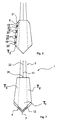
- FIG. 2 shows a further advantageous embodiment of a multipurpose binder 1.
- the two partial flaps T 2 and T 3 on the side have fastening means 10. These fasteners 10 are arranged so that they connect at least the two partial tabs T 2 and T 3 together.
- the fastening means 10 can be designed as buttons, push buttons, cuffs, needle-shaped or else in another way. Fastening with press studs is particularly useful when areas of the partial flaps T 2 and T 3 overlap.
- snap fasteners have the advantage that no button holes have to be made in the front part 4. If the front part 4 is made up of at least two layers of fabric, there is the possibility of making buttonholes in one layer of fabric without these being visible later in the visible area when the partial flaps are unfolded.
- the front part 4 preferably has an inner layer 11 and / or an insert 12 at least in one section.
- This inner layer 11 or insert 12 can consist of a firmer material, so that when the partial flaps T 2 and T 3 are folded together, a certain shape, for example of the front part 4, is predetermined. It is favorable if the inner layer 11 also has fastening means 10.
- the partial flap T 2 can be connected to the inner layer 11 first and then the partial flap T 3 via a button connection.
- the fastening means 10 can also be attached in such a way that a respective width of the front part 4 can be changed.
- the inner layer 11 can also be drawn over the entire width of the partial tabs T 1 , T 2 and T 3 and have a uniform pattern. Silk is the preferred material here.
- the inner layer 11 is fastened by means of an insert 12 which protrudes from the binding part 3.
- the insert 12 or the inner layer 11 can in turn have corresponding fastening means.
- the insert 12 extends through the binding part 3 to the neck part 2, where it preferably forms an upholstery thereof.
- the neck part 2 can be opened, so that the insert 12 or an inside in the neck area comes to rest.
- This inside is preferably made of silk, which can also be located on the corresponding side of the insert 12. It is favorable for production if the binding part 3 is sewn closed so that the insert 12 can be fastened to both the neck part 2 and the front part 4.
- the binding part 3 which is then subjected to the highest loads when it is pulled, therefore has a part of the seam that is present when the same is sewn together in tubular form as a particularly strong seam.
- This can also serve as a connection of the binding part with two or more partial lobes and / or adjoining areas, whereby it permanently prevents the hose formed thereby from tearing.
- Those seams that are subject to shear when opened are then made to be particularly durable. It is also favorable to additionally provide a seam as a lock, which is able to absorb shear forces.
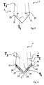
- Figure 3 shows a multi-purpose binder 1, in which the partial flaps T 2 and T 3 come to rest on the partial flap T 1 by folding.
- the front part 4 additionally has holding means 14.
- the holding means 14 is preferably designed so that it can be attached in a variable manner. In addition, it can accommodate the free end of the neck part 2 when a knot has been tied. This free end can also be passed through further holding means 14, which can advantageously also serve as fastening means 10 of the partial tabs T 2 and T 3 , for example in the form of a label.
- This combination of fastening means 10 and holding means 14 can also be achieved by means of needles or buttons and can be variably fastened with suitable parts.
- the holding means 14 serve to hold the free end of the neck part 2 and to indicate which material has been used in the multipurpose binder and which treatments can be carried out with regard to cleaning etc.
- Two of these holding means 14 are preferably fastened to the multi-purpose binder 1, as shown.
- there are sufficient holding options for the neck part 2 and on the other hand different information can be shown on a respective holding part 14. It is particularly advantageous if one of these holding means 14 is attached or can be attached where a connecting seam 13 merges between the front part and the neck part and offers additional protection against tearing and tearing of the seam.
- neck part 2 To hold the free end of the neck part 2 there is also a holding means 14 in the form of a loop, which is advantageously fastened in a hem of a partial flap. But slot-like configurations in a partial flap for passing the free end through can also be used.
- a further development of the neck part 2 provides that it has a replaceable cover 15, which is preferably tubular and can be pulled over. This facilitates a connection between the neck part 2 and the cover 15, which is advantageously fixed via a button connection.
- the coating 15 can be selected so that cleaning is possible.
- a favorable embodiment of the neck part 2 further provides that an associated part of the same, for example the insert 12 as such, is also interchangeable and preferably easy to clean.
- the freely foldable components of the multipurpose binder be it the partial flaps T 2 and T 3 or corresponding areas of the neck part 2, have fold-in incisions 16 which facilitate opening and closing and prevent wrinkling of an opened area.
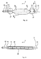
- FIG. 4 shows a preferred embodiment of a front part with three partial tabs T 1 , T 2 and T 3 .
- the partial flap T 3 and the partial flap T 2 are cut so that an overlapping fastening zone 17 is formed.
- This fastening zone 17 is preferably designed in such a way that the material used has a particular strength in order not to show any wear when fastening means are frequently attached and detached.
- the front part 4 in turn has an inner layer 11.
- the inner layer 11 is advantageously interchangeable, for which purpose it has corresponding fastening means with which it can be connected to the front part. Due to the requirements placed on a multi-purpose binder, it is favorable that not only the inner layer 11 but also the corresponding edges 8 of the front part 4 are edged. So they offer protection against fraying and wear.
- the corresponding widenings for an overlap are allowed to run smoothly. This prevents creasing or swelling of the front part. It is particularly advantageous if there is a large overlap in the upper region of the front part, preferably a larger overlap than in a lower region. This determines the shape of the multi-purpose tie as a tie due to the basic orientation of the upper area. A larger upper overlap area can be achieved, for example, by parallelism of the opened edges of the partial area of the front part.
- FIG. 5 shows a cross section through the front part 4 of FIG. 4, the fastening zone 17 being clearly visible.
- the partial flap T 2 covered by the partial flap T 3 has a special configuration in the fastening zone 17 in the form of a defined fastening surface 18 for a holding means.
- This fastening surface 18 has an insert 19 as protection against a piercing needle in the partial flap T 1 .
- This insert 19 has a trough, as a result of which it is possible to undercut the fastening surface 18 by means of a needle, without being able to pierce the partial flap T 1 . This prevents corresponding destruction of the partial flap T 1 and facilitates the use of fasteners.
- such protection preferably made of a plastic, enables a variable change in width due to the possibility of allowing the partial flaps T 2 and T 3 to lie differently one above the other.
- the insert 19 can be connected directly to the fastening surface 18. However, the most favorable location depends on which areas of the fabric are to be protected or where the protective device makes the most sense. A position of the protective device under the insert 12 is also preferred.
- FIG. 6 shows a further advantageous embodiment to ensure safe handling of fasteners.
- the partial flap T 3 has fastening surfaces 18 which are formed by corresponding stitched seams 20.
- the stitched seams 20 prevent tearing and tearing when the tensile load is too high on a fastener fastened in a fixed manner within the fastening surface 18.
- a stitched seam 20 is preferably applied to form a fastening surface 18 in the outer region of a partial flap.
- There it has a seam reinforcement 21, indicated by the dashed line, which reinforces the edge 8, preferably over a width of at least one centimeter. If the multipurpose tie 1 is to be portable on both sides, the stitched seams 20 are advantageously to be attached when binding an Ascot shape so that they are not visible.
- FIG. 7 shows a further embodiment of a multi-purpose binder 1.
- the binding part 3 has a common Liba seam 22, which merges into a reinforced seam 13 as tearing protection in the area that is particularly vulnerable to tension and shear. It is also favorable to put on a seam in the form of a transverse lock 26, which reinforces the tear protection.
- the partial tabs T 2 and T 3 are made up of two layers, each layer being made of a different material.
- the insert 12 In the area of the partial flap T 1 there is an insert 12 which extends from the binding part 3 to the tip 7 of the front part 4.
- the insert 12 then also serves as an inner lining.
- the insert 12 is connected to the binding part 3 by the Liba seam 22 or the seam 13, which prevents it from being pulled out.
- the insert 12 is thus connected in an unchangeable manner to the multipurpose binder 1 or is held as a removable part, for example with a Velcro fastener, and can therefore be replaced.
- the shape and the width of the front part 4 of a multipurpose truss 1 can also be changed as required.
- FIG. 8 illustrates a further preferred embodiment of a multipurpose binder 1.
- the section 5 of the front part 4 on the folding lines 6 between two partial flaps T 2 and T 1 or T 3 and T 1 has elements 23 as folding means which have a certain stiffening function with simultaneous Have hinge effect.
- the elements 23 can preferably be introduced in the partial region 5 so that they can be changed, so that in particular the folding line 6 can be displaced.
- the elements 23 can also be introduced into preformed pockets within the front part 4. This defines their position and thus that of the folding line 6. These pockets can also be designed such that an element can be displaced and fixed in a defined manner.
- FIG. 9 shows a further embodiment of an element 23.
- it connects the three partial tabs T 1 , T 2 and T 3 to one another, for this purpose it has struts 24 which are connected to one another in an articulated manner by means of suitable hinge-like devices 25.
- the hinge-like devices 25 can specify corresponding fold lines 6 of the partial flaps.
- the partial flaps can be folded together by means of suitable fastening means 10, such as a push-button system.
- the element 23 can also be detached from the partial tabs T 2 and T 3 and replaced by another element 23. As a result, other fold lines 6 can be achieved.
- Another advantage of this design is the weight concentration in the tip 7 of the front part 4. This ensures that the multipurpose binder 1 does not leave its correct position in a bound form on the neck even in adverse conditions, for example in strong winds.
- FIG. 10 shows a further advantageous embodiment of a multi-purpose binder 1 with a neck part 2.
- the neck part 2 in turn has an area that can be opened.
- three partial flaps T 1 , T 2 and T 3 are again present, which build up a collapsible neck part 2.
- the neck part 2 also has fabric areas 27 which are connected to the neck part 2 partially or entirely along their length.
- the fabric areas 27 have holding means 14, for example buttons or buttonholes, so that they enable the neck part 2 to be closed. By appropriate arrangement of the holding means 14, this closure can be kept variable in order to be adaptable to different neck widths.
- only one fabric region 27 and holding means required for this purpose are provided on the neck part 2 or in the region of the binding part 3.
- the Liba seam 22 in the neck part 2 or in the binding part 3 in turn has a reinforced seam 13 and a lock 26 by a transverse seam, which permanently prevent tearing or tearing of the sewn-together hose.
- the fabric areas 27 are much more likely to be contaminated than other parts of the multipurpose binder 1. Therefore, the fabric areas 27 are expediently cleanable. Interchangeability of these material areas 27 is particularly advantageously ensured. So these can either be washed or exchanged for new fabric areas 27.
- FIG. 11 shows a neck part 2 and part of a binding part 3, above a cover 15 has been pushed.
- This is with holding means 14th attached to the neck part 2, the corresponding holding means 14 in the neck part 2 are advantageously introduced so that when sewing the Liba seam 22 can also be attached.
- the cover 15 has slots 28 on. Through this can be opened with the neck part 2 closed Part of the front part of the multipurpose tie are pulled through. This also results in the possibility of closing the neck part 2 bring about.
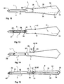
- Fig. 12 (1) shows another embodiment of a variable general-purpose truss 1 with a neck part 2, a binding part 3 and a front part 4.
- Das Neck part has a first fastening device 29, which is a spherical part a push button is formed.
- This ball part 29 is with a second fastening device 30 connectable, whereby the length of the Neck part 2 is changed.
- the second fastening device 30, which is designed as a spring head of a push button, can be taken along line 31 be adjusted. This allows flexibility in terms of length changes of the neck part 2.
- the binding part 3 is designed wider than the neck part 2.
- the multi-purpose binder 1 can be used well as a shawl tie.
- the multi-purpose binder 1 is a long binder usable. It is no longer necessary to wear it, for example a celebration has passed from the official part to the more unofficial part, the neck part 2 is shortened and a wider one in the wider binding part Ascot-shaped knot tied.
- the multi-purpose binder 1 is shown in FIG. 12 in the opened state.
- the respective folding seams 35 between the partial flaps 32, 33, 34 are indicated by dashed lines.
- the folding seams 35 do not hear in the area between the binding part 3 and the front part 4. Rather extend they also extend into the binding part 3. This can also be along the predetermined Fold seam 35 change its width.
- the course is here, however adapted so that the conventional, familiar form of a long tie through the illustrated multipurpose binder 1 can be shaped.
- a binding 36 is arranged in the binding part 3 and the front part 4. This can be a loop, a label or an incision in the binding part 3 or front part 4.
- Through the implementation 36 is the shortened To pull neck part 2, which forms a loop. This loop is placed around the neck of a person and then the opened one Tie part 3 by own multiple wrapping to a cloth to train.
- the loop formation and variable use of the multipurpose tie 1 is illustrated again in FIGS. 21 to 44.
- the neck part 2 has a first 37 and a second 38 V-shaped blank. This allows the width of the neck part 3 to be changed repeatedly. Will the two V-shaped blanks 37, 38 exerted train, so that is in between located material 39 stretched. This material is advantageous 39 a stretch fabric, which changes the width as well as the length supported. This is located between the two blanks 37, 38 Material 39 also has flexibility in aligning it by 30 ° to 60 °, advantageously 45 ° opposite other orientations of the material 39 or this other materials 40. This is shown in FIG. 13 by corresponding Ruling indicated. Furthermore, the front part 4 has means 41 Wrinkling on.
- the second partial flap has 33 shirring tapes 41, which are folded over in this illustration and therefore extend invisible first 32 and third 34 partial lobes.
- the shirring straps 17 ensure that the partial flaps 32, 33, 34 pull apart widely.
- FIG. 14 shows a variable multi-purpose binder 1, which features from FIG. 12 and Fig. 13 connects together.
- the general purpose binder shown in Fig. 14 1 can be used to form loops like a knot be used.
- the fastening devices 29, 30 can on the here Center seam, not shown, or also offset to sit.
- a side Offset of both fastening devices 29, 30 secures when the Length a uniform coverage of the coming to lie on top of each other Neck part 2.
- a needle 42 as passage 36 attached.
- This has a protective cap 43, which has a means 44 for attachment on the multipurpose truss 1. This is shown in FIG.
- the Implementation 36 in the form of a needle 42 is in this way can be flexibly attached to the multipurpose truss 1. Suitable for the scope of a Neck is then the length 3 correspondingly adjustable by length suitable displacement of the needle 42.
- the Binding part 3 also have markings 45, the corresponding fixing points proposes for implementation 36.
- Preferred dimensions for the Length of the binding part 3 are between 55 and 35 cm, preferably about 45 cm.
- a preferred length range for a full length drawn neck part 2 has approximately the same dimensions. There is an invoice to bear that for oversize or undersize, of course, other dimensions are necessary could be. Other differences in length dimensions are may also depend on whether the variable multi-purpose binder 1 is designed solely for loop formation or knot tying.
- Fig. 15 shows another variable multi-purpose binder 1, which is also the Possibility of loop formation combined with a knot tie.
- the Multi-purpose binder 1 is sewn together like a tube. It can be seen in the Neck part 2 a first seam 46. This connects the tube 47 with itself itself. This first seam 46 is interrupted by the first fastening device 29. This can be connected to the second fastening device 30. Due to the arrangement of the two fastening devices 29, 30 in the neck part 2, this in turn is reduced to about half can be shortened. Between the first fastening device 29 and the second The fastening device 30 is the hose 47, which forms the neck part 2, open along line 48.
- the width of the Neck part 2 is changed so that no longer a narrow neck part 2 for a shirt collar, but a wide neck part 2 for, for example, direct Neck contact is present.
- This then shell-like application of the multi-purpose binder 1 can be further developed by using 47 formwork materials in the interior of the hose be used. These can be particularly skin-friendly substances. For a high wearing comfort of the multi-purpose binder 1 is particularly Silk, cashmere or similar comparable high quality is used.
- the second fastening device 30 serves not only as a counterpart to the first fastening device 29. Rather, it also has the Task to combine different layers of fabric. This can Layer of fabric of the neck part 2 or the binding part 3. Of the second fastening device 30 leads a second seam 49 to the front part 4.
- the front part 4 again has a first 32, second 33 and third 34 partial lobes. These can be opened along the folding seam 35. So that the second seam 49 does not tear when opened, is located in the Transition area between the binding part 3 and the front part as a passage 36 a label 50.
- the label 50 serves similarly as tearing protection an end region 51 of the first seam 46 designed as a lock the rest are also the first 29 and / or second 30 fastening device Can be attached like a lock in the multipurpose truss 1.
- the label is 50 at its opposite edges 52 preferably with a double seam attached, which is next to or on top of each other. This can cause pulling through of the neck part 2 by the label 50 the latter not without raw Violence can be separated from the multipurpose truss 1.
- Area of the folding seam 35 of the multipurpose tie 1 in FIG. 15 the fabric, especially the outer fabric, woven so that it is thinner there other adjacent areas. This is for example by a 45 ° offset weaving of warp and weft possible.
- Another possibility, to support the folding at the folding seam 35 is to To connect partial flaps 32, 33, 34 there so that one Art Nut is created. This is also possible by using thinner fabric there is used.
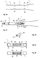
- FIG. 16 shows an embodiment of a multipurpose truss 1 in a detail.
- constrictions 53 in the material of the multi-purpose binder 1 introduced.
- These constrictions prevent when closing and opening parts of the multipurpose truss 1, for example the partial flap 32, 33, 34 or the one to be opened Area of the neck part 2, there is overlap of the material.
- the Material overlaps lead to thickening, especially on the neck area can lead to pressure marks and chafing marks.
- By suitable Cutting in those areas where opening and closing or there is another change in width is the superimposition prevented from material.
- Such a cut, for example the constriction 53 is also with the V-shaped blank 37, 38 in FIG. 17 can be combined.
- Between the neck part 3 and the front part 4 is still arranged as an incision 68 into which the free end of the Neck part 4 can be inserted at the desired shortening.
- the 17 shows a further multipurpose binder 1.
- This has a first one Fastening device 29, which is only visible because of an outbreak 54 is shown.
- the first fastening device 29 in the neck part 2 is a rivet button. This goes through all the superimposed fabrics, but is covered by sewing the hose 47 together.
- the Rivet head 29 can also be covered on its other side by hose 47 his. Then he holds together those layers of fabric that are in tube 47 are located.
- the rivet head 29 is both Sides visibly attached and then holds the hose 47 with.
- the second Fastening device 30 can be covered by a substance additive 55. In the 17, the additive 55 is lifted so that the second Fastening device 30 is visible.
- the fabric additive 55 can be in the neck part 2 be attached so that the fastening device 30 in one with it trained kind of niche disappears. Only then does it become this exposed when needed.
- the substance additive 55 also continues to serve for protection. It prevents the second fastening device 30 from directly can come into contact with the neck. This avoids injuries, for example by abrasions when moving the multipurpose truss 1 the throat.
- the multipurpose binder 1 shown in FIG. 17 has in addition to the second Fastening device 30 which is adjacent to the beginning 56 of the changeable Neck region is arranged, a third fastening device 57.
- the third fastening device 57 is adjacent to the bushing 36 arranged.
- the passage 36 designed as a label 50, enables again the loop formation of the multi-purpose binder 1.
- the multi-purpose tie 1 can be worn as a long tie, for men People come into question.
- in its function as an Ascot Shawls are more likely to be male and female.
- the Fastening devices 30, 57 can in particular be arranged such that they correspond to the average of the male or female neck.
- the third fastening device 57 has a material cover 59 on, which is indicated as check.
- the material cover 59 in turn serves for protection. At the same time, it also serves as insulation. Is the Multipurpose truss 1 in a cold environment, so it is for one person uncomfortable when metal parts of the multi-purpose binder are adapted to this temperature 1 come into direct skin contact. The material cover 59 prevents this. According to another idea of the invention to see an inner layer 11 in the beginning 56 of the changeable neck region. As already indicated here, this can be pulled out of the hose 47. The inner layer 11 thus serves to widen the neck part 2 when in use the multipurpose truss 1 as a scarf.
- the inner layer 11 is no longer required, it can be stuffed back into the hose 47.
- the inner layer 11 is fastened in the multipurpose truss 1. This was done with this Design of the multipurpose truss 1 including the third Fastening device 57. This ensures that the insert 12th not torn from multipurpose truss 1 even with strong tensile forces can be.
- Fig. 18 shows a cross bar 60.
- the cross bar 60 is a bushing 36 can be used, but can also within the hose 47 and thus in Be used inside the multi-purpose binder 1. It advantageously serves as a holder for fabric areas of the multi-purpose binder 1.
- a layer 62 is arranged around a core 64. This can be made of fabric or other materials. Layer 62 is in one embodiment is rotatable about the core 61. In another Execution, the layer 62 has such a low coefficient of friction on the fact that a substance passed past it also over longer periods of time Use of the multi-purpose binder 1 no or only imperceptible signs of wear will have.
- a Insert 12 is arranged inside the multi-purpose binder 1. She will through the inner layer 11 on one side and on the other side the back 63 of the second partial flap 33 is held.
- the insert 12 is can be used to give the multi-purpose binder l a shape. She is too usable to create a warming effect in the neck area. Not only an insert 12 may be located in the second partial flap 33.
- the first Partial flap 32 and the third partial flap 34 can also have an insert 12 exhibit. These are otherwise not visible in this cross-section would be indicated by dashed lines.
- the multipurpose truss 1 can thus have several Have deposits 12, which can also be contiguous and as single insert 12 are formed.
- the insert 12 is in another Design interchangeably arranged in the multipurpose truss 1. same for also for the inner layer 11. Furthermore, the inner layer 11 with the insert 12 can also be attached, the multi-purpose binder 1 also additional Can have fasteners for the insert 12. These are for example Tabs, loops or loops.
- the inner layer 11 can also a label or other implementation that is not shown here, be attached.
- the folding seams 35 shown are designed so that a permanent bond between the parts thus assembled consists. On the other hand, they specify the fold-out line along which the first partial flap 32 and the third partial flap 33 are folded.
- FIG. 20 shows a further cross section through another multi-purpose binder 1.
- the insert 12 is held by the cross bar 60.
- This configuration is useful for interchangeable inserts 12 because this facilitates the implementation of the insert 12 in the multipurpose binder 1.
- By using multiple crossbars 60 along the length of the multipurpose truss 1 ensures that the insert 12 does not slip.
- On Replacement of the insert 12 is for example by pulling it out of the Start 56 of the changeable neck area of the neck part 2 from FIG. 6 possible.
- the tube 47 is then open to the inside and is not sewn shut.
- the third fastening device can then be used to fix the insert 12 57 serve in Fig. 17. This is then designed so that it is inside the Hose 47 has an attachment option with a corresponding Attachment possibility on the insert 12 is connectable.
- the core 61 of the cross bar 60 is indicated by dashed lines. Should the Layer 62 can be rotated, the core 61 is fastened in the folding seams 36.
- the insert 12 is only in one embodiment of a multi-purpose binder 1 a part of the front part 4 arranged in a different embodiment the insert 12 extends over the entire front part and at least partly in the binding part 3. Also several inserts 12 are in a row can be arranged in multipurpose truss 1.
- the neck part 2 has in one expedient embodiment no insert 12 in those areas that can be widened or extended.
- the multi-purpose binder 1 provides thus a new combination due to its possible use as a long tie with the as a scarf.
- the 21 shows the multipurpose truss 1 in its form as a long truss.
- the first fastening device 29, shown in more detail in FIG. 22, and the second fastening device 30, shown in more detail in FIG. 23, are fixable with each other. Between them is the neck part 2.
- the multi-purpose binder 1 has a label 50 as passage 36. Between the second Fastening device 30 and the label 50 is the binding part 3.
- In Front part 4 is a needle 42 in specially provided incisions 64 supported.
- the neck part 2 and the binding part 3 together have the length A.
- the binding part 3 has the length B and the neck part 2 the length H.
- This three lengths A, B, H are to be interpreted so that on the one hand the condition for the use of the multipurpose truss 1 as a long truss is fulfilled.
- the length H must be such that at Use the multipurpose truss 1 as a scarf is still sufficient Length for wrapping the neck is available.
- the length B of the binding part 3 it is preferred that it lasts at least as long extends that with a neck part folded around a neck 2 and subsequent Wrapping the binding part 3 after double folding the implementation 36 does not get into the knot thus formed.
- each length B selected so that the implementation with a predetermined bond 36 just lies on the formed knot and the front part 4 can be opened.
- each length B also adapted to a specific binding, for example a Winsork knot.
- FIG. 27 shows how the half neck part 2 is passed through the label 50, whereby viewed from the front, the multi-purpose truss shown in Fig. 28 1 trains.
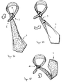
- FIG. 29 shows the formation of loops of the first loop 65 by crossover of the half binding part 2 through the unfolded front part 4.
- Das Front part 4 is now from below along the direction of the arrow upwards passed through the first loop 65. This results in the first winding in the multi-purpose truss 1, as shown in Fig. 30, just executed becomes.
- Fig. 31 shows the half neck part 2 as it is under the opened front part 4 peeps out.
- the front part 4 is particularly long from the bottom to through the loop at the top and then around it again until the Label 50 is no longer visible but is wrapped within Area.
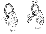
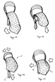
- Fig. 32 shows the side view again Wrapping area 66, in which the half neck part 2 is so movable, that the neck size can be reduced by pulling. This Change in neck size is also shown in Fig. 33.
- the multipurpose truss 1 has a neck part 2 that can be opened. This is through the first fastening device 29 and the second fastening device 30 limited. Furthermore, the front part 4 can also be opened. Unfolding the first partial flap 32 and the third partial flap 33 is limited by the label 50, which tears the second Seam 49 is prevented, as is the second fastening device 30 first fastening device 29 prevents tearing of the first seam 46. As shown in FIG. 35, the neck area 2 that is now opened by crossing with the front part 4 and the binding part 3 to the first Loop 65 formed. The front part 4 is then from below inside the first loop 65 and the top of the thus formed Sling pulled out. As shown in FIG.
- FIG. 37 it is shown how the front part 4 with the not yet wrapped area of the binding part 3 is rotated by 180 °. Then, as shown in FIG. 38, the front part is pushed back into the Loop looped around the wrap area 66, so that the in Fig. 39 shown state of the multipurpose truss 1 results.
- Fig. 40 shows how the front part 4 over the wrapping area 66 and so that it is also guided over the neck part 2 projecting downwards before it can be pulled back through the loop from the bottom up.
- This wrapping in circular movements with right-hand winding will Tie part 3 is formed until the label 50 is outside of the wrapping area 66 thus formed is no longer visible from the outside is. This is necessary because the label 50 is the beginning of the unfoldability the partial rag indicates.
- the process of the last winding is in the Figures 41 and 42 shown.
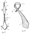
- the knotted multipurpose tie shown in Fig. 43 is related its neck width by pulling on the neck part 2 also like a loop formation adjustable. Once the appropriate neck size has been found, the procedure shown in Fig. 44, the unfolded front area 4 is pulled apart again, that the wrapping area 66 is no longer visible to the outside.
- the structure of the multipurpose truss and the type of binding clarify that in contrast to the knot formation in normal long binders, in which the loop for knot formation from the protruding length of the would depend on the front part, which defines the visible length of this, with multipurpose truss 1, the wrap for knot formation depends on Binding part 3 and from the beginning of the opening of the front part 4 is.
- Figure 45 shows yet another possibility, the total length of a multipurpose truss 1 to vary. Sections of the multipurpose truss 1 are overlapped and by means of the first 29 and second 30 fastening device connected with each other.
- Figure 46 shows a particularly advantageous length distribution between the neck part (2), binding part (3) and front part (4) when shortened to a cloth.
- the Front part has a length between 40 cm and 60 cm, in particular about 50 cm. This length is sufficient for use as a tie as well as a cloth.
- FIG. 47 shows how the one surrounding the first fastening device 29 Fabric at least partially has a gathering 67. This detail is for Designing a protection of the skin when binding the multi-purpose binder with the first fastening device 29 or the second fastening device 30 comes into contact. Through the gathering 67, the fastening device 29 at least partially covered with the fabric. The Gathering 67 can also be carried out so that the fastening device 29 in this virtually disappears and is only exposed, even if the fastening device 29 is used.
- the multipurpose binder according to the invention is characterized by its diversity for different occasions, be it official or casual like using a multipurpose truss on different occasions are also combinations of different fabrics and materials in different sections of the multi-purpose binder possible, depending on A more skin-friendly fabric compared to one, for example more decorative fabric can be chosen.
- a multipurpose truss that can be designed in this way also offers the possibility of not only appropriately by men, but also by women as a scarf or the like to be worn with blouses.
Landscapes
- Engineering & Computer Science (AREA)
- Textile Engineering (AREA)
- Decoration Of Textiles (AREA)
- Details Of Garments (AREA)
- Outerwear In General, And Traditional Japanese Garments (AREA)
- Use Of Switch Circuits For Exchanges And Methods Of Control Of Multiplex Exchanges (AREA)
- Detergent Compositions (AREA)
- Holders For Apparel And Elements Relating To Apparel (AREA)
Claims (57)
- Elément de nouage à usages multiples (1) avec une longueur totale, d'une partie de cou (2) avec une largeur, une partie de nouage (3) et une partie avant (4), la partie de nouage (3) pouvant être enlacée en un noeud, l'élément de nouage à usages multiples se présentant en une seule pièce et étant variable grâce à une structure d'au moins une zone partielle (5) de la partie avant (4) d'une première longueur (1) d'au moins 15 cm à partir d'au moins deux pans partiels (T1, T2) pouvant être librement pliés, caractérisé en ce queune variabilité supplémentaire est donnée.grâce à une possibilité d'ajustage de la longueur totale de l'élément de nouage à usages multiples, la longueur totale pouvant être modifiée de façon répétée, et/ougrâce á une possibilité d'ajustage de la largeur de la partie de cou (2), la largeur pouvant être modifiée de façon répétée,
- Elément de nouage à usages multiples (1) selon la revendication 1,
caractérisé en ce que la partie avant (4) est structurée au moins dans une zone partielle (5) d'au moins trois pans partiels (T1, T2, T3 ) pouvant être pliés librement. - Elément de nouage à usages multiples (1) selon la revendication 1 ou 2,
caractérisé en ce que un pan partiel (T1, T2, T3) peut être fixé de façon détachable répétée au moins avec un autre pan partiel (T1, T2, T3), ceux-ci présentant de préférence des moyens de fixation (10) appropriés à cet effet. - Elément de nouage à usages multiples (1) selon l'une des revendications précédentes, caractérisé en ce que la zone partielle pouvant être dépliée (5) de la partie avant (4) a une longueur (1) d'au moins 30 cm et de préférence d'au moins 35 cm.
- Elément de nouage à usages multiples (1) selon l'une des revendications précédentes, caractérisé en ce que la largeur d'au moins la zone partielle (5) de la partie avant (4) peut être modifiée de façon ajustable.
- Elément de nouage à usages multiples (1) selon l'une des revendications précédentes, caractérisé en ce que la largeur de la zone partielle (5) de la partie avant (4) peut être dépliée à partir d'une largeur préalablement ajustée et correspondant à une largeur d'un élément allongé de nouage (1), en celle d'un foulard pouvant notamment être agrandie d'au moins 25 %, de préférence de plus de 50 %, notamment de 100 % et plus.
- Elément de nouage à usages multiples (1) selon l'une des revendications précédentes, caractérisé en ce que la zone partielle (5) pouvant être dépliée a une longueur (1) d'au moins 40 cm, les pans partiels (T1, T2, T3) pouvant de préférence être rabattus librement jusqu'à la pointe (7) de la partie avant (4) de l'élément de nouage à usages multiples (1).
- Elément de nouage à usages multiples (1) selon l'une des revendications précédentes, caractérisé en ce qu'au moins dans la zone partielle (5) le long d'un bord (8) de la partie avant (4) se trouve un renforcement d'ourlet (21).
- Elément de nouage à usages multiples (1) selon l'une des revendications précédentes, caractérisé en ce que celui-ci présente au moins une marque (9) qui indique un début de la partie devant être enlacée avec elle-même de l'élément de nouage à usages multiples (1).
- Elément de nouage à usages multiples (1) selon l'une des revendications précédentes, caractérisé en ce que la mesure de la longueur de la partie de nouage (3) est fixée de telle façon que dans le cas d'un enlacement multiple de la partie de nouage (3) avec elle-même pour la formation d'un noeud un tronçon de la zone partielle (5) dépliable de la partie avant (4) se trouve au-dessus ou tout juste après le noeud créé.
- Elément de nouage à usages multiples (1) selon l'une des revendications précédentes, caractérisé en ce que la longueur (B) de la partie de nouage (3) est adaptée à un nouage pour la formation d'un noeud prédéterminé.
- Elément de nouage à usages multiples (1) selon l'une des revendications précédentes, caractérisé en ce que le matériau ou les matériaux au moins de la partie de nouage (3) est ou sont au moins cousu(s) partiellement en forme de tuyau, au moins la partie principale de la partie avant (4) et/ou de la partie de cou (2) pouvant être rabattue(s) librement.
- Elément de nouage à usages multiples (1) selon l'une des revendications précédentes, caractérisé en ce que pour la liaison d'au moins deux pans partiels (T1, T2, T3) et/ou de tronçons de la partie de nouage (3) et/ou de tronçons de la partie de cou (2) en un tuyau et/ou de zones adjacentes une couture (13) est réalisée de manière telle qu'une déchirure est empêchée de façon durable.
- Elénient de nouage à usages multiples (1) selon l'une des revendications précédentes, caractérisé en ce qu'au moins la surface de la partie de cou (2), étant tournée vers le cou, présente un autre matériau que la surface étant détournée du cou.
- Elément de nouage à usages multiples (1) selon l'une des revendications précédentes, caractérisé en ce qu'au moins une zone de la partie de cou (2) présente un revêtement (15) ou un empiècement (19) remplaçable, ces derniers notamment pouvant être nettoyés, qui de préférence est réalisé en forme de tuyau.
- Elément de nouage à usages multiples (1) selon l'une des revendications précédentes, caractérisé en ce que une zone de la partie de cou (2) peut être pliée.
- Elément de nouage à usages multiples (1) selon l'une des revendications précédentes, caractérisé en ce que la partie de cou (2) présente une possibilité de fixation propre.
- Elément de nouage à usages multiples (1) selon l'une des revendications précédentes, caractérisé en ce que la partie avant (4) présente au moins partiellement une couche intérieure (11) et/ou une garniture (12) qui de préférence décrit une ligne de pliage (6), notamment une couche intérieure changeable (11) et/ou une garniture (12), qui possède de préférence au moins dans la zone partielle (5) pouvant être rabattue, le même matériau que la face de la partie avant (4) étant visible quand l'élément de nouage à usages multiples (1) est porté.
- Elément de nouage à usages multiples (1) selon l'une des revendications précédentes, caractérisé en ce que la couche intérieure (11) et/ou la garniture (12) présente des moyens de fixation (10).
- Elément de nouage à usages multiples (1) selon l'une des revendications précédentes, caractérisé en ce qu'il existe au moins une surface de fixation définie (18) pour un moyen de fixation (10) et/ou des moyens de retenue (14), notamment pour un moyen de fixation en forme d'épingle, dans l'entourage de cette surface se trouvant un dispositif de protection (19).
- Elément de nouage à usages multiples (1) selon l'une des revendications précédentes, caractérisé en ce que les pans partiels (T1, T2, T3) pouvant être rabattus de la partie avant (4) se chevauchent au moins partiellement en formant une forme d'élément allongé de nouage et réalisent une zone de fixation (17).
- Elément de nouage à usages multiples (1) selon l'une des revendications précédentes, caractérisé en ce qu'il y a au moins un moyen de retenue (14) pour la retenue d'un tronçon de l'élément de nouage à usages multiples (1), notamment d'un tronçon d'extrémité de la partie de cou (2) le moyen de retenue (14) pouvant de préférence être rapporté de façon changeable, de préférence en forme d'une étiquette ou d'une boucle.
- Elément de nouage à usages multiples (1) selon l'une des revendications précédentes, caractérisé en ce que la longueur (H) et/ou la largeur de sa partie de cou (2) est au moins partiellement modifiable de façon répétée.
- Elément de nouage à usages multiples (1) selon l'une des revendications précédentes, caractérisé en ce que la partie de cou (2) est au moins partiellement dépliable de façon répétée.
- Elément de nouage à usages multiples (1) selon l'une des revendications précédentes, caractérisé en ce que qu'une zone d'extrémité (56) d'une zone dépliable de la partie de cou (2) présente une coupe(37, 38), soutenant le dépliage, notamment une coupe en forme de V.
- Elément de nouage à usages multiples (1) selon l'une des revendications précédentes, caractérisé en ce que la zone dépliable présente une orientation de tissu (39) tournée de 30° à 60°, notamment de 45°, par rapport à une autre zone (40) de l'élément de nouage à usages multiples (1).
- Elément de nouage à usages multiples (1) selon l'une des revendications précédentes, caractérisé en ce que la longueur totale de l'élément de nouage à usages multiples (1), de préférence la partie de cou (2) dans la longueur (H), peut être raccourcie fixée de façon répétée et à nouveau être rallongée.
- Elément de nouage à usages multiples (1) selon l'une des revendications précédentes, caractérisé en ce que la longueur totale de l'élément de nouage à usages multiples (1), notamment la partie de cou (2), peut être modifiée par ajustation.
- Elément de nouage à usages multiples (1) selon l'une des revendications précédentes, caractérisé en ce qu'au moins la partie de cou (2) présente au moins un dispositif de fixation (29, 30).
- Elément de nouage à usages multiples (1) selon la revendication 29,
caractérisé en ce que le dispositif de fixation (29, 30) est au moins adjacent d'un début (32) de la zone de cou pouvant être changée. - Elément de nouage à usages multiples (1) selon l'une des revendications précédentes, caractérisé en ce que un dispositif de fixation (29, 30) se trouve au moins adjacent de la partie de nouage (3).
- Elément de nouage à usages multiples (1) selon l'une des revendications précédentes, caractérisé en ce que un dispositif de fixation (29, 30) se trouve au moins adjacent d'un passage (36, 42).
- Elément de nouage à usages multiples (1) selon la revendication 32,
caractérisé en ce que le passage (36, 42) est une étiquette (50), une boucle (60) ou une incision (68) dans la partie de nouage (3) ou dans la partie avant (4), le passage (36, 42) étant agencé de préférence au moins adjacent d'un début d'une partie avant (4) dépliable. - Elément de nouage à usages multiples (1) selon l'une des revendications précédentes, caractérisé en ce que les dispositifs de fixation (29, 30) peuvent être reliés entre eux.
- Elément de nouage à usages multiples (1) selon l'une des revendications précédentes, caractérisé en ce que le dispositif de fixation (29, 30) est recouvert au moins partiellement de matériau (55, 59), notamment de tissu.
- Elément de nouage à usages multiples (1) selon l'une des revendications précédentes, caractérisé en ce que le dispositif de fixation (29, 30) fixe des couches de tissu entre elles.
- Elément de nouage à usages multiples (1) selon l'une des revendications précédentes, caractérisé en ce que le dispositif de fixation (29, 30) peut être caché de telle manière qu'il n'est pas visible.
- Elément de nouage à usages multiples (1) selon l'une des revendications précédentes, caractérisé en ce que le matériau présente un retroussement (67) adjacent du dispositif de fixation (29, 30).
- Elément de nouage à usages multiples (1) selon l'une des revendications précédentes, caractérisé en ce que le dispositif de fixation (29, 30) est une tête à ressort ou une pièce sphérique d'un bouton-pression.
- Elément de nouage à usages multiples (1) selon l'une des revendications précédentes, caractérisé en ce que la partie de nouage (3) est aussi longue qu'à partir de celle-ci un noeud peut être noué avec deux à cinq, de préférence trois enlacements, avec elle-même.
- Elément de nouage à usages multiples (1) selon la revendication 40,
caractérisé en ce que le passage (36, 42) est agencé de telle manière qu'il disparaít dans le noeud. - Elément de nouage à usages multiples (1) selon la revendication 40 ou 41,
caractérisé en ce que le passage (36, 42) est agencé au moins adjacent de la partie avant (4). - Elément de nouage à usages multiples (1) selon l'une des revendications précédentes, caractérisé en ce que la partie avant (4) est dépliable jusqu'à une protection à la déchirure (29, 50, 51), notamment jusqu'à un verrouillage et/ou un passage (36, 42).
- Elément de nouage à usages multiples (1) selon l'une des revendications précédentes, caractérisé en ce que la partie avant (4) et/ou des parties adjacentes présentent des moyens (41) de formation de plis.
- Elément de nouage à usages multiples (1) selon l'une des revendications précédentes, caractérisé en ce que les pans partiels (32, 33, 34) sont rattachés l'un à l'autre, notamment cousus, une couche intérieure (11) et/ou une garniture (12) étant de préférence cousue à l'intérieur.
- Elément de nouage à usages multiples (1) selon l'une des revendications précédentes, caractérisé en ce que celui-ci a une couche intérieure(11) et/ou une garniture (12) qui est composée de tissu de foulard, notamment de cachemire.
- Elément de nouage à usages multiples (1) selon l'une des revendications précédentes, caractérisé en ce que la garniture est collée et cousue.
- Elément de nouage à usages multiples (1) selon l'une des revendications précédentes, caractérisé en ce que la garniture (12) est fixée à la couche intérieure (11).
- Elément de nouage à usages multiples (1) selon l'une des revendications précédentes, caractérisé en ce que la garniture (12) est fixée de façon échangeable, notamment adjacente du passage (36, 42) et/ou du dispositif de fixation (29, 30).
- Elément de nouage à usages multiples (1) selon l'une des revendications précédentes, caractérisé en ce que le passage (36, 42) est une épingle (42) avec un capot protecteur (43) pour une pointe de l'épingle (42).
- Elément de nouage à usages multiples (1) selon l'une des revendications précédentes comportant une épingle (42) avec une pointe, un capot protecteur (43) étant agencé sur la pointe, l'épingle (42) et/ou le capot protecteur (43) ayant un moyen supplémentaire (44) pour la fixation à l'élément de nouage à usages multiples (1).
- Elément de nouage à usages multiples (1) comportant une partie de cou (2), une partie de nouage (3) et une partie avant (4), la partie de nouage (3) pouvant être enlacée en un noeud, une garniture (12) ou une couche intérieure (11) pouvant être tirée hors d'une ouverture, notamment d'une fente, dans une partie de l'élément de nouage à usages multiples (1), de préférence dans la partie de nouage (3) ou la partie avant (4), la garniture (12) ou la couche intérieure (11) étant conçue en forme de foulard, caractérisé en ce que la garniture (12) ou la couche intérieure (11) est plus large en état retiré que la partie avant de l'élément de nouage à usages multiples (1) en forme d'élément allongé de nouage.
- Elément de nouage à usages multiples (1) selon l'une des revendications précédentes, avec un revêtement (15) pouvant être nettoyé, notamment lavable, en forme de tuyau, le revêtement (15) présentant au moins deux fentes (28) pour tirer à travers au moins une partie de la partie avant (4).
- Procédé pour la transformation d'un élément de nouage à usages multiples avec une partie de cou (2), une partie de nouage (3) et une partie avant (4), notamment d'un élément de nouage à usages multiples (1) selon l'une des revendications précédentes, d'une forme de cravate en une forme de foulard avec les étapes suivantes :la transformation pouvant être à nouveau rétrogradée et l'élément de nouage à usages multiples (1) pouvant être utilisé comme cravate.raccourcissement répétable de la partie de cou (2) au moyen d'un dispositif de fixation (29, 30),dépliage d'au moins deux pans partiels (32, 33, 34) pouvant être pliés librement de la partie avant (4) jusqu'à un passage (36) et/ou jusqu'à une couture protégée contre la déchirure, notamment un verrouillage (26) dans la partie avant (4),enlacement de la partie de nouage (3) aussi longtemps autour d'elle-même que le passage (36) et/ou la couture disparaít tout juste sous un noeud de foulard formé en l'occurrence etcouverture du noeud de tissu réalisé avec le pan partiel déplié (32, 33, 34),
- Procédé selon la revendication 54 comportant une introduction partielle de la partie de cou (2) raccourcie à travers un passage (36).
- Procédé selon la revendication 54 ou 55 avec l'enlacement de la partie de nouage et formation du noeud de foulard de telle façon que par traction à la partie de cou (2) une largeur de cou est ajustée.
- Procédé selon l'une des revendications précédentes comportant un élargissement pouvant être répété d'une zone de la partie de cou (2).
Applications Claiming Priority (5)
| Application Number | Priority Date | Filing Date | Title |
|---|---|---|---|
| DE19626991 | 1996-07-04 | ||
| DE1996126991 DE19626991A1 (de) | 1996-07-04 | 1996-07-04 | Mehrzweck-Langbinder mit einem Halsteil, einem Bindeteil und einem Vorderteil |
| DE29701067U DE29701067U1 (de) | 1997-01-22 | 1997-01-22 | Variabler Mehrzweckbinder |
| DE29701067U | 1997-01-22 | ||
| PCT/EP1997/003525 WO1998001045A1 (fr) | 1996-07-04 | 1997-07-03 | Cravate variable, d'une seule piece, a usages multiples |
Publications (2)
| Publication Number | Publication Date |
|---|---|
| EP0912115A1 EP0912115A1 (fr) | 1999-05-06 |
| EP0912115B1 true EP0912115B1 (fr) | 2001-04-04 |
Family
ID=26027209
Family Applications (1)
| Application Number | Title | Priority Date | Filing Date |
|---|---|---|---|
| EP97932772A Expired - Lifetime EP0912115B1 (fr) | 1996-07-04 | 1997-07-03 | Cravate variable, d'une seule piece, a usages multiples |
Country Status (7)
| Country | Link |
|---|---|
| US (1) | US6209136B1 (fr) |
| EP (1) | EP0912115B1 (fr) |
| AT (1) | ATE200187T1 (fr) |
| AU (1) | AU3620197A (fr) |
| CA (1) | CA2262742A1 (fr) |
| DE (1) | DE59703300D1 (fr) |
| WO (1) | WO1998001045A1 (fr) |
Families Citing this family (11)
| Publication number | Priority date | Publication date | Assignee | Title |
|---|---|---|---|---|
| ITBO20020013U1 (it) * | 2002-02-08 | 2003-08-08 | Alessandro Mattioli | Cravatta a tre o piu' pale e nodo pluristrato |
| US7065794B2 (en) * | 2003-03-19 | 2006-06-27 | Richard Anderson | Secure necktie |
| USD666380S1 (en) * | 2011-03-11 | 2012-09-04 | Peacock Apparel Group, Inc. | Tie and handkerchief retail combination |
| USD666382S1 (en) * | 2011-05-23 | 2012-09-04 | Peacock Apparel Group, Inc. | Combination of ties for retail display |
| USD671709S1 (en) * | 2011-06-28 | 2012-12-04 | Dominick Michael Cicerchia | Neckwear |
| USD666383S1 (en) * | 2011-08-03 | 2012-09-04 | Peacock Apparel Group, Inc. | Combination of ties for retail display |
| USD666381S1 (en) * | 2011-08-03 | 2012-09-04 | Peacock Apparel Group, Inc. | Tie and handkerchief retail combination |
| US9375039B2 (en) * | 2013-10-04 | 2016-06-28 | Brandon William ETHERIDGE | Interchangeable tie |
| US20190125014A1 (en) * | 2017-10-30 | 2019-05-02 | Marie Keenan | Headband with Infinity Scarf |
| US12245644B2 (en) * | 2022-04-28 | 2025-03-11 | Tamika MAYES | Support garments |
| US20260107999A1 (en) * | 2024-10-21 | 2026-04-23 | Justin Matthew Hicken | Necktie securing device, and related devices, systems, and methods |
Family Cites Families (13)
| Publication number | Priority date | Publication date | Assignee | Title |
|---|---|---|---|---|
| FR659742A (fr) * | 1928-07-12 | 1929-07-02 | Cravate à nouer perfectionnée | |
| FR846674A (fr) * | 1938-11-28 | 1939-09-21 | Perfectionnements aux cravates dites régates | |
| DE815936C (de) * | 1948-10-02 | 1951-10-04 | Fritz Dipl-Ing Ewert | Befestigungsvorrichtung fuer Krawatten und aehnliche Bekleidungsstuecke |
| DE6913333U (de) | 1969-03-29 | 1970-01-22 | Wolfram Juergens | Krawatte nach art eines langbinders |
| US3881196A (en) | 1973-08-07 | 1975-05-06 | Andrea Spada | Tie arrangements and tie-holding device therefor |
| US4613992A (en) * | 1985-05-24 | 1986-09-30 | Dabbieri Claudai L | 9/1 necktie |
| FR2593680A1 (fr) | 1986-02-03 | 1987-08-07 | Olivier Gilles | Cravate surprise : noeud papillon dans la cravate |
| CH669714A5 (fr) | 1987-02-28 | 1989-04-14 | Laurette Heim | |
| DE8800518U1 (de) * | 1988-01-18 | 1988-03-31 | Müller, Wilhelm, 8033 Planegg | Krawatte |
| CA1317698C (fr) * | 1989-06-06 | 1993-05-18 | Eugene J. Marostica | Cravate |
| DE9206006U1 (de) * | 1992-05-04 | 1992-07-30 | Hosse Accessoires und Krawattenfabrik vormals Würsch & Co., Zürich | Krawatte |
| IT226805Z2 (it) | 1992-07-24 | 1997-07-01 | Mantero Seta S P A | Cravatta componibile |
| US5435011A (en) | 1993-08-27 | 1995-07-25 | Nicolai; John H. | Necktie with pocket |
-
1997
- 1997-07-03 WO PCT/EP1997/003525 patent/WO1998001045A1/fr not_active Ceased
- 1997-07-03 AU AU36201/97A patent/AU3620197A/en not_active Abandoned
- 1997-07-03 CA CA002262742A patent/CA2262742A1/fr not_active Abandoned
- 1997-07-03 AT AT97932772T patent/ATE200187T1/de not_active IP Right Cessation
- 1997-07-03 EP EP97932772A patent/EP0912115B1/fr not_active Expired - Lifetime
- 1997-07-03 DE DE59703300T patent/DE59703300D1/de not_active Expired - Fee Related
- 1997-07-03 US US09/214,319 patent/US6209136B1/en not_active Expired - Fee Related
Also Published As
| Publication number | Publication date |
|---|---|
| EP0912115A1 (fr) | 1999-05-06 |
| ATE200187T1 (de) | 2001-04-15 |
| US6209136B1 (en) | 2001-04-03 |
| DE59703300D1 (de) | 2001-05-10 |
| WO1998001045A1 (fr) | 1998-01-15 |
| CA2262742A1 (fr) | 1998-01-15 |
| AU3620197A (en) | 1998-02-02 |
Similar Documents
| Publication | Publication Date | Title |
|---|---|---|
| DE2330996A1 (de) | Elastikband, insbesondere zur verwendung in kleidungsstuecken | |
| DE1785428C3 (de) | Einteiliger Kinderschlafanzug und Verfahren zu seiner Herstellung | |
| EP0912115B1 (fr) | Cravate variable, d'une seule piece, a usages multiples | |
| DE69418880T2 (de) | Bekleidungsstück | |
| CH695531A5 (de) | Verschlusselement und zweiteiliges Bekleidungsstück mit einem solchen Verschlusselement. | |
| DE3113598A1 (de) | Bekleidungsstueck in form eines gewebeschlauches und verfahren zu seiner herstellung | |
| DE60105751T2 (de) | Materiale oder produkte die, streifen aus natürlichem oder künstlichem pelz, gebrauchen | |
| DE60217640T2 (de) | In ein oder zwei Teilen verwendbares Kleidungstück | |
| EP1869988A1 (fr) | Pièce de revêtement dotée d'au moins un cordon | |
| CH684867A5 (de) | Krawatte. | |
| DE102016004469B4 (de) | Zusätzliche Lochleiste zum nachträglichen Einbringen in Bekleidung | |
| DE29701067U1 (de) | Variabler Mehrzweckbinder | |
| DE19626991A1 (de) | Mehrzweck-Langbinder mit einem Halsteil, einem Bindeteil und einem Vorderteil | |
| DE2231019A1 (de) | Krawattenschal | |
| AT514872B1 (de) | Halsbekleidungselement | |
| DE19747616C1 (de) | Umhang, insbesondere Mantel | |
| DE827336C (de) | Hosentraeger | |
| DE256957C (fr) | ||
| DE3687528T2 (de) | Oberhemd mit halsöffnung. | |
| DE19918381A1 (de) | Eine vereinfachte Verschlußvorrichtung für Jacken und Mäntel aller Art | |
| DE3305502C2 (de) | Sakko mit Bequemlichkeitsfalten | |
| DE202021001665U1 (de) | Größenverstellbares, schützendes Kopftuch zum Binden | |
| DE2002592A1 (de) | Kleidungsstueck mit verstellbarer Taillenweite | |
| DE19900606C1 (de) | Hemd und Krawatte | |
| AT502796B1 (de) | Einsatzelement für bekleidungsstücke |
Legal Events
| Date | Code | Title | Description |
|---|---|---|---|
| PUAI | Public reference made under article 153(3) epc to a published international application that has entered the european phase |
Free format text: ORIGINAL CODE: 0009012 |
|
| 17P | Request for examination filed |
Effective date: 19990111 |
|
| AK | Designated contracting states |
Kind code of ref document: A1 Designated state(s): AT BE CH DE ES FR GB IE IT LI NL SE |
|
| GRAG | Despatch of communication of intention to grant |
Free format text: ORIGINAL CODE: EPIDOS AGRA |
|
| 17Q | First examination report despatched |
Effective date: 20000417 |
|
| GRAG | Despatch of communication of intention to grant |
Free format text: ORIGINAL CODE: EPIDOS AGRA |
|
| GRAH | Despatch of communication of intention to grant a patent |
Free format text: ORIGINAL CODE: EPIDOS IGRA |
|
| GRAH | Despatch of communication of intention to grant a patent |
Free format text: ORIGINAL CODE: EPIDOS IGRA |
|
| GRAA | (expected) grant |
Free format text: ORIGINAL CODE: 0009210 |
|
| AK | Designated contracting states |
Kind code of ref document: B1 Designated state(s): AT BE CH DE ES FR GB IE IT LI NL SE |
|
| PG25 | Lapsed in a contracting state [announced via postgrant information from national office to epo] |
Ref country code: NL Free format text: LAPSE BECAUSE OF FAILURE TO SUBMIT A TRANSLATION OF THE DESCRIPTION OR TO PAY THE FEE WITHIN THE PRESCRIBED TIME-LIMIT Effective date: 20010404 Ref country code: IT Free format text: LAPSE BECAUSE OF FAILURE TO SUBMIT A TRANSLATION OF THE DESCRIPTION OR TO PAY THE FEE WITHIN THE PRE;WARNING: LAPSES OF ITALIAN PATENTS WITH EFFECTIVE DATE BEFORE 2007 MAY HAVE OCCURRED AT ANY TIME BEFORE 2007. THE CORRECT EFFECTIVE DATE MAY BE DIFFERENT FROM THE ONE RECORDED.SCRIBED TIME-LIMIT Effective date: 20010404 Ref country code: IE Free format text: LAPSE BECAUSE OF FAILURE TO SUBMIT A TRANSLATION OF THE DESCRIPTION OR TO PAY THE FEE WITHIN THE PRESCRIBED TIME-LIMIT Effective date: 20010404 |
|
| REF | Corresponds to: |
Ref document number: 200187 Country of ref document: AT Date of ref document: 20010415 Kind code of ref document: T |
|
| REG | Reference to a national code |
Ref country code: CH Ref legal event code: EP |
|
| REG | Reference to a national code |
Ref country code: IE Ref legal event code: FG4D Free format text: GERMAN |
|
| REF | Corresponds to: |
Ref document number: 59703300 Country of ref document: DE Date of ref document: 20010510 |
|
| PG25 | Lapsed in a contracting state [announced via postgrant information from national office to epo] |
Ref country code: SE Free format text: LAPSE BECAUSE OF FAILURE TO SUBMIT A TRANSLATION OF THE DESCRIPTION OR TO PAY THE FEE WITHIN THE PRESCRIBED TIME-LIMIT Effective date: 20010704 |
|
| RAP2 | Party data changed (patent owner data changed or rights of a patent transferred) |
Owner name: OPHARDT, THOMAS |
|
| RIN2 | Information on inventor provided after grant (corrected) |
Free format text: OPHARDT, THOMAS |
|
| REG | Reference to a national code |
Ref country code: CH Ref legal event code: NV Representative=s name: BUGNION S.A. |
|
| GBT | Gb: translation of ep patent filed (gb section 77(6)(a)/1977) |
Effective date: 20010710 |
|
| ET | Fr: translation filed | ||
| NLV1 | Nl: lapsed or annulled due to failure to fulfill the requirements of art. 29p and 29m of the patents act | ||
| PG25 | Lapsed in a contracting state [announced via postgrant information from national office to epo] |
Ref country code: ES Free format text: LAPSE BECAUSE OF FAILURE TO SUBMIT A TRANSLATION OF THE DESCRIPTION OR TO PAY THE FEE WITHIN THE PRESCRIBED TIME-LIMIT Effective date: 20011030 |
|
| REG | Reference to a national code |
Ref country code: GB Ref legal event code: IF02 |
|
| PLBE | No opposition filed within time limit |
Free format text: ORIGINAL CODE: 0009261 |
|
| STAA | Information on the status of an ep patent application or granted ep patent |
Free format text: STATUS: NO OPPOSITION FILED WITHIN TIME LIMIT |
|
| REG | Reference to a national code |
Ref country code: IE Ref legal event code: FD4D |
|
| 26N | No opposition filed | ||
| PGFP | Annual fee paid to national office [announced via postgrant information from national office to epo] |
Ref country code: FR Payment date: 20020717 Year of fee payment: 6 |
|
| PGFP | Annual fee paid to national office [announced via postgrant information from national office to epo] |
Ref country code: BE Payment date: 20020723 Year of fee payment: 6 |
|
| PGFP | Annual fee paid to national office [announced via postgrant information from national office to epo] |
Ref country code: CH Payment date: 20020726 Year of fee payment: 6 |
|
| PGFP | Annual fee paid to national office [announced via postgrant information from national office to epo] |
Ref country code: DE Payment date: 20020827 Year of fee payment: 6 |
|
| PG25 | Lapsed in a contracting state [announced via postgrant information from national office to epo] |
Ref country code: LI Free format text: LAPSE BECAUSE OF NON-PAYMENT OF DUE FEES Effective date: 20030731 Ref country code: CH Free format text: LAPSE BECAUSE OF NON-PAYMENT OF DUE FEES Effective date: 20030731 Ref country code: BE Free format text: LAPSE BECAUSE OF NON-PAYMENT OF DUE FEES Effective date: 20030731 |
|
| PGFP | Annual fee paid to national office [announced via postgrant information from national office to epo] |
Ref country code: GB Payment date: 20031128 Year of fee payment: 7 |
|
| BERE | Be: lapsed |
Owner name: *OPHARDT THOMAS Effective date: 20030731 |
|
| PG25 | Lapsed in a contracting state [announced via postgrant information from national office to epo] |
Ref country code: DE Free format text: LAPSE BECAUSE OF NON-PAYMENT OF DUE FEES Effective date: 20040203 |
|
| REG | Reference to a national code |
Ref country code: CH Ref legal event code: PL |
|
| PG25 | Lapsed in a contracting state [announced via postgrant information from national office to epo] |
Ref country code: FR Free format text: LAPSE BECAUSE OF NON-PAYMENT OF DUE FEES Effective date: 20040331 |
|
| REG | Reference to a national code |
Ref country code: FR Ref legal event code: ST |
|
| PG25 | Lapsed in a contracting state [announced via postgrant information from national office to epo] |
Ref country code: GB Free format text: LAPSE BECAUSE OF NON-PAYMENT OF DUE FEES Effective date: 20040703 |
|
| GBPC | Gb: european patent ceased through non-payment of renewal fee |
Effective date: 20040703 |
|
| PGFP | Annual fee paid to national office [announced via postgrant information from national office to epo] |
Ref country code: AT Payment date: 20050722 Year of fee payment: 9 |
|
| PG25 | Lapsed in a contracting state [announced via postgrant information from national office to epo] |
Ref country code: AT Free format text: LAPSE BECAUSE OF NON-PAYMENT OF DUE FEES Effective date: 20060703 |