EP0912876B1 - Podometre - Google Patents
Podometre Download PDFInfo
- Publication number
- EP0912876B1 EP0912876B1 EP97929486A EP97929486A EP0912876B1 EP 0912876 B1 EP0912876 B1 EP 0912876B1 EP 97929486 A EP97929486 A EP 97929486A EP 97929486 A EP97929486 A EP 97929486A EP 0912876 B1 EP0912876 B1 EP 0912876B1
- Authority
- EP
- European Patent Office
- Prior art keywords
- signal
- running
- distance covered
- unit
- walking
- Prior art date
- Legal status (The legal status is an assumption and is not a legal conclusion. Google has not performed a legal analysis and makes no representation as to the accuracy of the status listed.)
- Expired - Lifetime
Links
- 230000000295 complement effect Effects 0.000 claims abstract description 4
- 210000002683 foot Anatomy 0.000 claims description 30
- 238000001514 detection method Methods 0.000 claims description 9
- 235000019577 caloric intake Nutrition 0.000 claims description 5
- 210000003423 ankle Anatomy 0.000 claims description 4
- 238000004364 calculation method Methods 0.000 claims description 4
- 239000004973 liquid crystal related substance Substances 0.000 claims description 4
- 239000000919 ceramic Substances 0.000 claims description 2
- 238000006243 chemical reaction Methods 0.000 claims description 2
- 239000013078 crystal Substances 0.000 claims description 2
- 238000000034 method Methods 0.000 abstract description 7
- 238000010586 diagram Methods 0.000 description 9
- 238000005259 measurement Methods 0.000 description 8
- XLYOFNOQVPJJNP-UHFFFAOYSA-N water Substances O XLYOFNOQVPJJNP-UHFFFAOYSA-N 0.000 description 3
- 244000025254 Cannabis sativa Species 0.000 description 1
- 230000005540 biological transmission Effects 0.000 description 1
- 238000010276 construction Methods 0.000 description 1
- 238000011156 evaluation Methods 0.000 description 1
- 230000006870 function Effects 0.000 description 1
- 230000000873 masking effect Effects 0.000 description 1
- 239000011150 reinforced concrete Substances 0.000 description 1
- 230000002787 reinforcement Effects 0.000 description 1
- 230000035939 shock Effects 0.000 description 1
- 230000001360 synchronised effect Effects 0.000 description 1
- 238000002604 ultrasonography Methods 0.000 description 1
- 238000004148 unit process Methods 0.000 description 1
Images


Classifications
-
- G—PHYSICS
- G01—MEASURING; TESTING
- G01C—MEASURING DISTANCES, LEVELS OR BEARINGS; SURVEYING; NAVIGATION; GYROSCOPIC INSTRUMENTS; PHOTOGRAMMETRY OR VIDEOGRAMMETRY
- G01C22/00—Measuring distance traversed on the ground by vehicles, persons, animals or other moving solid bodies, e.g. using odometers, using pedometers
- G01C22/006—Pedometers
-
- A—HUMAN NECESSITIES
- A43—FOOTWEAR
- A43B—CHARACTERISTIC FEATURES OF FOOTWEAR; PARTS OF FOOTWEAR
- A43B3/00—Footwear characterised by the shape or the use
-
- A—HUMAN NECESSITIES
- A43—FOOTWEAR
- A43B—CHARACTERISTIC FEATURES OF FOOTWEAR; PARTS OF FOOTWEAR
- A43B3/00—Footwear characterised by the shape or the use
- A43B3/34—Footwear characterised by the shape or the use with electrical or electronic arrangements
Definitions
- the present invention relates to the measurement of the distances covered and the speeds reached by walking and/or running people.
- system A) based on the use of ultrasounds has to be discarded both because of the fragility of the transducers which cannot withstand the mechanical stress in such an application and the difficulty of protecting them from water splashes (rain, puddles, etc.).
- System B) based on the use of radiofrequency signals has big application problems because it requires calibrations and is particularly sensitive to thermal variations. In order to overcome such problems it would be necessary to resort to a very expensive apparatus which would not be recommended for a commercial production.
- the drawback of system C) using a magnetic flow consists in that it is strongly depending on the type of pavement on which the user runs or walks causing high variations of parameters and characteristics of the detection system. To sum up, the method involving fewer problems of the measurement and display system is that of item D) above, i.e. that using an infrared transmitting/receiving system.
- the present invention seeks to overcome the problems mentioned above by providing a portable apparatus able to calculate with high precision the distance covered and the speed.
- the apparatus according to the invention essentially consists of two separate, complementary, electronic devices, one of which (slave) is able to transmit signals through suitable transmitting means, while the other (master) is able to receive said signals through suitable receiving means and to store and to process them so as to calculate the distance covered and the average and maximum speeds.
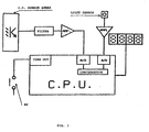
- FDM the measurement and display system
- the left foot at “lf” the right foot at “rf”
- the data display system at “display” the infrared ray at "I.R.”
- I.R the infrared ray at "I.R.”
- the construction and the design of FDM is made depend on that the mechanical stress, to which the apparatus is subjected, causes components requiring calibration such as resistive and capacitive trimmers as well as all of the components sensitive to mechanical shocks and vibrations to be avoided.
- sharp temperature variations can occur (e.g. when the foot accidentally ends up into a water puddle with lower temperature).
- the FDM consists of two complementary devices: "master” and “slave” supplied by cells and described below in their basic components.
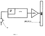
- the master essentially includes:
- the slave essentially includes:
- Both units are provided with a self-switching on/off system so as to avoid any control by the user and at the same time to optimize the cell consumption.
- This is accomplished by two pressure sensors SP which enable the respective unit as soon as a change of state of the sensor occurs.
- the enabling condition of the units is kept until a change of state of the respective sensor SP is detected within a predetermined time-out. Therefore, as soon as the feet move both master and slave units begin their operations.
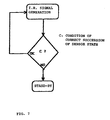
- any change of state of the relative pressure sensor SP causes the slave unit to leave the "sleep" state (stand-by with the minimum power consumption). At this time the time-out counting begins (fig.
- the first state takes place at the beginning of the movement when the feet are still and laid down.
- the second state takes place when the left foot is raised to start walking.
- sensor pressure SP changes its state and causes the slave unit to operate and to emit an infrared signal which is kept also when the foot is laid down again.
- the third state takes place after the end of the step of the left foot and the following raising of the right foot which causes the master unit to operate.
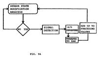
- the master unit operated by the change of state of pressure sensor SP detects the I.R. signal and stores a digit according to the amplitude of the latter.
- the master unit detects the signal at any change of state of its pressure sensor, i.e. both upon raising and laying down the right foot.
- the reverse succession takes place, i.e. the right foot is raised first, there are no problems because in this case the master unit is already operating when raising the left foot and then detects the modulated I.R. signal as soon as the slave unit starts the emission of the same.
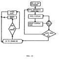
- the master unit processes then the amplitude of the I.R.
- Such data are stored in the memory and can be increased by next movements or can be reset by a reset button.
- the user In case the user is running, there is one more succession of states in the table shown above. Actually it should be considered the situation in which both feet are raised. Moreover, the feet can rotate backwards upon running with the result of a masking of the I.R. signal.
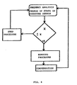
- the master unit is able to evaluate whether the user is walking or running (fig. 9) by only detecting the succession and the frequency of the changes of state of its pressure sensor. In such case, the signal measurement process is started in advance with respect to the time in which the right foot (where the master unit is installed) is laid down again. The amount of such a time in advance is proportional to the speed and can change every moment.
- the measurement is carried out before the foot rotates backwards. The same will take place before the foot is raised.
- the measurement of the signal is made in advance with respect to the time in which the right foot is raised from the ground.
- the time in advance in which the modulated I.R. signal is detected during the run is calculated by CPU according to the frequency of laying down/raising the foot to which the master unit is connected and depending on data stored in the memory and/or the program of CPU.
- a second embodiment of the invention further provides a calculation of the calories consumed by the user along a predetermined path.
- the master unit also provides a weight sensor such as a load cell able to evaluate the weight of the user.
- the CPU of the master unit calculates the calories employed during the walking and/or the run by comparing the detected weight, the distance covered, and the speed with its own data stored in the memory of the calculation program.
- Such beforehand obtained data e.g. during experimentations
Landscapes
- Engineering & Computer Science (AREA)
- Physics & Mathematics (AREA)
- General Physics & Mathematics (AREA)
- Radar, Positioning & Navigation (AREA)
- Remote Sensing (AREA)
- Microelectronics & Electronic Packaging (AREA)
- Photoreceptors In Electrophotography (AREA)
- Measuring Pulse, Heart Rate, Blood Pressure Or Blood Flow (AREA)
- Footwear And Its Accessory, Manufacturing Method And Apparatuses (AREA)
- Measurement Of Distances Traversed On The Ground (AREA)
- Optical Radar Systems And Details Thereof (AREA)
- Measurement Of The Respiration, Hearing Ability, Form, And Blood Characteristics Of Living Organisms (AREA)
- Rehabilitation Tools (AREA)
- Length Measuring Devices With Unspecified Measuring Means (AREA)
Claims (14)
- Appareil pour la mesure de la distance parcourue en marchant ou en courant à pied prévu pour être intégré aux chaussures, caractérisé par deux dispositifs électroniques séparés et complémentaires alimentés par des cellules, l'un d'entre eux étant fixé sur une chaussure et susceptible de générer des signaux par un moyen approprié d'émission alors que l'autre est fixé sur l'autre chaussure et est susceptible de recevoir ces signaux par un moyen approprié de réception et de les mémoriser et de les traiter de façon à les convertir en code binaire, ce faisant de pouvoir calculer la distance parcourue par le coureur ou le piéton ainsi que les vitesses moyennes et maximales, et de les afficher immédiatement, ces signaux étant modulés et directifs de façon que la distance à laquelle ils sont reçus par l'unité maítre est proportionnelle à la distance existant entre le moyen d'émission et le moyen de réception, des moyens pour l'affichage des données traitées étant en outre prévus.
- Appareil selon la revendication 1, caractérisé en ce que pour l'unité d'émission fixée sur l'une des chaussures et pour l'unité de réception est fixée sur l'autre chaussure sont prévus des moyens d'autocommutation comprenant une unité logique (CPU) activée par des capteurs de pression (SP) appropriés, et en association, lorsqu'un changement d'état de ces capteurs se produit, les conditions d'activation étant maintenues pendant une durée prédéterminée à la fin de laquelle les unités sont automatiquement coupées, afin d'éviter toute commande par l'utilisateur, et en même temps de minimiser la consommation d'énergie provenant des cellules.
- Appareil pour mesurer la distance parcourue en marchant ou en courant selon la revendication 1, caractérisé par le fait que l'on prévoit un moyen pour la conversion du signal en un signal numérique dès que reçu par l'unité maítre et pour sa comparaison à la tension de référence, un chiffre binaire entre 0 et 255 étant obtenu et mémorisé dans un registre, ledit registre étant complété par addition jusqu'aux valeurs mémorisées précédemment jusqu'à ce qu'il soit complet, et en ce que l'on prévoit d'autres registres pour charger les chiffres binaires suivants, les données relatives à la distance totale couverte, à la vitesse moyenne et maximale étant automatiquement affichées immédiatement après que l'unité de réception soit revenue à l'état d'attente, c'est-à-dire exactement lorsque le coureur s'arrête de courir ou de marcher.
- Appareil pour la mesure de la distance parcourue en marchant ou en courant selon les revendications 1 et 2, caractérisé en ce que les registres sont en ordre croissant et représentent les unités, les dizaines, les centaines et les milliers.
- Appareil selon l'une quelconque des revendications précédentes, caractérisé en ce que les signaux directionnels sont des rayons infrarouges modulés.
- Appareil selon l'une quelconque des revendications précédentes, caractérisé en ce que les moyens émetteurs sont des diodes électroluminescentes émettrices dans l'infrarouge et les moyens de réception sont des photodiodes réceptrices.
- Appareil selon l'une quelconque des revendications précédentes, caractérisé en ce que l'unité émettrice se compose essentiellement de :et en ce que l'unité de réception se compose essentiellement de :un générateur d'impulsions alimentant en signaux impulsionnels les diodes électroluminescentes émettrices en infrarouge ;un amplificateur tampon de courant pour la commande des diodes électroluminescentes émettrices dans l'infrarouge ;un réseau de diodes électroluminescentes émettrices dans l'infrarouge disposées de façon préférentielle en demi-cercle autour de la face intérieure de la cheville gauche et enfermées dans un carter ;un capteur de pression (SP) susceptible de commuter entre marche et arrêt l'émission du rayonnement infrarouge ;une unité logique (CPU) pour commander le fonctionnement de l'appareil,une unité logique comprenant un microcalculateur susceptible d'effectuer des calculs mathématiques et prévu pour commander un afficheur ;un afficheur à cristaux liquides pour l'affichage de données relatives à la distance parcourue, à la vitesse moyenne, et à la vitesse maximale etc...un capteur de pression (SP) pour la détection du mouvement effectif du pied droit, permettant de synchroniser la détection du signal et la commutation automatique marche/arrêt de l'appareil ;un réseau de capteurs (récepteurs infrarouges) disposés en demi-cercle autour de la face intérieure de la cheville droite et enfermés dans un carter pour les protéger contre le rayonnement solaire ;un filtre sélectionnant le signal infrarouge modulé à la sortie des capteurs infrarouges ;un amplificateur de signal dont le gain est réglé de façon que la valeur maximale du signal amplifié soit toujours inférieure ou égale à la valeur maximale admissible pour CPU de façon à ne pas saturer le convertisseur analogique/numérique et éviter la détection d'erreurs ;un capteur de la lumière extérieure pour la compensation automatique du signal à différentes heures de la journée et dans le cas de la traversée rapide d'endroits sombres.
- Appareil selon la revendication 7, caractérisé en ce que les caractéristiques de l'unité logique CPU de l'unité de réception proviennent de :une gamme de températures de fonctionnement suffisamment large ;une alimentation en tension de valeur suffisamment basse (2-3 V) ;une consommation d'énergie très basse en mode attente (de l'ordre de quelques fractions de microampères) ;une interface de commande d'un afficheur à cristaux liquides et génératrice de signaux carrés ;un convertisseur analogique/numérique pour la mesure de l'amplitude du signal ;une résolution d'au moins 8 bits ;un générateur de référence en tension stable en température ;un oscillateur résonnant de référence en céramique (plus robuste qu'un oscillateur à cristal) ayant une fréquence située le plus près possible de la fréquence maximale permise du microcalculateur, et du résonateur.
- Appareil selon la revendication 7, caractérisé en ce que l'amplificateur est de grande stabilité en température et de très faible consommation électrique (CMOS).
- Appareil selon l'une quelconque des revendications 7 à 9, caractérisé en ce que l'unité logique du circuit maítre arrive à faire la différence entre l'état de marche ou de course de l'utilisateur à partir des données détectées par le capteur de pression et dans le cas de l'utilisateur qui court, de déclencher en avance la détection des signaux reçus par les photodiodes en fonction aussi bien de la durée pendant laquelle le pied est posé par terre que la durée pendant laquelle le pied est levé.
- Appareil selon la revendication 10, caractérisé en ce que la durée d'avance est calculée par l'unité logique (CPU) de l'unité de réception ou du circuit maítre en comparant les données détectées avec celles mémorisées dans son programme de commande.
- Appareil selon l'une quelconque des revendications précédentes, caractérisé en ce que l'unité de réception comporte en outre un capteur de poids tel qu'une jauge de contrainte capable d'évaluer le poids de l'utilisateur, l'unité logique possédant également un programme pour calculer la consommation de calories selon le poids, la distance couverte et la vitesse.
- Appareil selon la revendication 12, caractérisé en ce que le calcul de la consommation de calories est réalisé en comparant les données détectées avec celles mémorisées dans le programme de calcul.
- Appareil selon la revendication 13, caractérisé en ce que ce programme de calcul comporte un algorithme d'interpolation de données susceptible de réduire la quantité de données mémorisées et donc la taille de la mémoire de l'unité logique.
Applications Claiming Priority (3)
| Application Number | Priority Date | Filing Date | Title |
|---|---|---|---|
| ITRM960464 | 1996-06-28 | ||
| IT96RM000464A IT1284186B1 (it) | 1996-06-28 | 1996-06-28 | Dispositivo di misurazione della distanza percorsa a piedi (camminando o correndo) , applicabile all'interno di calzature o di |
| PCT/IT1997/000151 WO1998000683A1 (fr) | 1996-06-28 | 1997-06-26 | Podometre |
Publications (2)
| Publication Number | Publication Date |
|---|---|
| EP0912876A1 EP0912876A1 (fr) | 1999-05-06 |
| EP0912876B1 true EP0912876B1 (fr) | 2002-11-20 |
Family
ID=11404315
Family Applications (1)
| Application Number | Title | Priority Date | Filing Date |
|---|---|---|---|
| EP97929486A Expired - Lifetime EP0912876B1 (fr) | 1996-06-28 | 1997-06-26 | Podometre |
Country Status (9)
| Country | Link |
|---|---|
| US (1) | US6243659B1 (fr) |
| EP (1) | EP0912876B1 (fr) |
| JP (1) | JP2000513448A (fr) |
| AT (1) | ATE228238T1 (fr) |
| AU (1) | AU3357797A (fr) |
| CA (1) | CA2257520A1 (fr) |
| DE (1) | DE69717278T2 (fr) |
| IT (1) | IT1284186B1 (fr) |
| WO (1) | WO1998000683A1 (fr) |
Families Citing this family (15)
| Publication number | Priority date | Publication date | Assignee | Title |
|---|---|---|---|---|
| US6738726B2 (en) * | 2000-12-07 | 2004-05-18 | Bbc International, Ltd. | Apparatus and method for measuring the maximum speed of a runner over a prescribed distance |
| US6805006B2 (en) * | 2000-12-07 | 2004-10-19 | Bbc International, Ltd. | Method and apparatus for measuring the maximum speed of a runner over a prescribed distance including a transmitter and receiver |
| US6658079B1 (en) * | 2002-07-29 | 2003-12-02 | Hewlett-Packard Development Company, L.P. | System, method and apparatus for measuring walking and running distance |
| JP2005267152A (ja) * | 2004-03-18 | 2005-09-29 | Seiko Instruments Inc | 電子歩数計 |
| GR1005785B (el) * | 2005-05-19 | 2008-01-29 | Βασιλικη-Ειρηνη Στραπατσακη | Συσκευη μετρησης διανυομενων αποστασεων απο δρομεα |
| JP4830789B2 (ja) * | 2006-10-30 | 2011-12-07 | オムロンヘルスケア株式会社 | 体動検出装置、情報送信装置、ノルディックウォーキング用ストック、および歩行運動量算出システム |
| CN103182175B (zh) | 2007-02-14 | 2015-09-16 | 耐克创新有限合伙公司 | 运动信息的收集和显示 |
| US8253586B1 (en) | 2009-04-24 | 2012-08-28 | Mayfonk Art, Inc. | Athletic-wear having integral measuring sensors |
| US9855484B1 (en) | 2009-04-24 | 2018-01-02 | Mayfonk Athletic, Llc | Systems, methods, and apparatus for measuring athletic performance characteristics |
| US8990045B2 (en) * | 2009-11-18 | 2015-03-24 | Silicon Valley Micro E Corp. | Pedometer with shoe mounted sensor and transmitter |
| TWI495849B (zh) * | 2010-11-25 | 2015-08-11 | Silicon Valley Micro E Corp | 安裝感測器與傳送器之鞋的計步器 |
| EP2458338B1 (fr) * | 2010-11-25 | 2014-12-31 | Silicon Valley Micro E Corporation | Pédomètre doté d'un capteur et d'un transmetteur montés sur la chaussure |
| CN102564448B (zh) * | 2010-12-10 | 2016-06-08 | 硅谷微E股份有限公司 | 具有鞋装传感器和发射机的计步器 |
| CN109282806B (zh) * | 2017-07-20 | 2024-03-22 | 罗伯特·博世有限公司 | 用于确定步行者位置的方法、装置和存储介质 |
| FR3072251B1 (fr) | 2017-10-16 | 2021-02-26 | Zhor Tech | Dispositif electronique pour produits chaussants. |
Family Cites Families (10)
| Publication number | Priority date | Publication date | Assignee | Title |
|---|---|---|---|---|
| JPS57151807A (en) * | 1981-03-16 | 1982-09-20 | Secoh Giken Inc | Distance measuring device |
| US4578769A (en) | 1983-02-09 | 1986-03-25 | Nike, Inc. | Device for determining the speed, distance traversed, elapsed time and calories expended by a person while running |
| DE3405081A1 (de) * | 1984-02-13 | 1985-08-14 | Puma-Sportschuhfabriken Rudolf Dassler Kg, 8522 Herzogenaurach | Sportschuh fuer laufdisziplinen und verfahren zur informationsabgabe und/oder zum informationsaustausch ueber bewegungsablaeufe bei laufdisziplinen |
| DE3505521A1 (de) * | 1985-02-18 | 1986-08-21 | Puma-Sportschuhfabriken Rudolf Dassler Kg, 8522 Herzogenaurach | Anlage zur ermittlung der bewegungsablaeufe bei laufdisziplinen |
| DE3514130A1 (de) * | 1985-04-19 | 1985-11-07 | Klaus-Dieter 7060 Schorndorf Hufenbach | Geh-, lauf- und bewegungsmesser, welcher mit hilfe von strahlen, schwingungen oder wellen die geschwindigkeiten, rhythmen und zeitablaeufe misst |
| US5033013A (en) * | 1985-04-22 | 1991-07-16 | Yamasa Tokei Meter Co., Ltd. | Method and apparatus for measuring the amount of exercise |
| US4741001A (en) * | 1986-05-02 | 1988-04-26 | Robert Ma | Pedometer stop watch |
| US5117444A (en) * | 1990-07-30 | 1992-05-26 | W. Ron Sutton | High accuracy pedometer and calibration method |
| US5724265A (en) * | 1995-12-12 | 1998-03-03 | Hutchings; Lawrence J. | System and method for measuring movement of objects |
| US6073086A (en) * | 1998-01-14 | 2000-06-06 | Silicon Pie, Inc. | Time of motion, speed, and trajectory height measuring device |
-
1996
- 1996-06-28 IT IT96RM000464A patent/IT1284186B1/it active IP Right Grant
-
1997
- 1997-06-26 WO PCT/IT1997/000151 patent/WO1998000683A1/fr not_active Ceased
- 1997-06-26 AT AT97929486T patent/ATE228238T1/de not_active IP Right Cessation
- 1997-06-26 AU AU33577/97A patent/AU3357797A/en not_active Abandoned
- 1997-06-26 JP JP10503972A patent/JP2000513448A/ja not_active Ceased
- 1997-06-26 DE DE69717278T patent/DE69717278T2/de not_active Expired - Fee Related
- 1997-06-26 US US09/202,334 patent/US6243659B1/en not_active Expired - Fee Related
- 1997-06-26 EP EP97929486A patent/EP0912876B1/fr not_active Expired - Lifetime
- 1997-06-26 CA CA002257520A patent/CA2257520A1/fr not_active Abandoned
Also Published As
| Publication number | Publication date |
|---|---|
| AU3357797A (en) | 1998-01-21 |
| ITRM960464A0 (fr) | 1996-06-28 |
| DE69717278T2 (de) | 2003-07-24 |
| WO1998000683A1 (fr) | 1998-01-08 |
| EP0912876A1 (fr) | 1999-05-06 |
| JP2000513448A (ja) | 2000-10-10 |
| ITRM960464A1 (it) | 1997-12-28 |
| IT1284186B1 (it) | 1998-05-08 |
| DE69717278D1 (en) | 2003-01-02 |
| HK1019786A1 (en) | 2000-02-25 |
| ATE228238T1 (de) | 2002-12-15 |
| US6243659B1 (en) | 2001-06-05 |
| CA2257520A1 (fr) | 1998-01-08 |
Similar Documents
| Publication | Publication Date | Title |
|---|---|---|
| EP0912876B1 (fr) | Podometre | |
| US6014100A (en) | Two-wire RADAR sensor with intermittently operating circuitry components | |
| US7791715B1 (en) | Method and system for lossless dealiasing in time-of-flight (TOF) systems | |
| US4763287A (en) | Measuring performance information in running disciplines and shoe systems | |
| US6741343B2 (en) | Level with angle and distance measurement apparatus | |
| US7409312B2 (en) | Handheld laser light detector with height correction, using a GPS receiver to provide two-dimensional position data | |
| US20110188028A1 (en) | Methods and systems for hierarchical de-aliasing time-of-flight (tof) systems | |
| EP0721595B1 (fr) | Detecteur laser capable de mesurer la distance, la vitesse et l'acceleration | |
| US3900259A (en) | Time interval phase detection in distance measuring apparatus | |
| US6708570B2 (en) | Flow rate measurement method, ultrasonic flow rate meter, flow velocity measurement method, temperature or pressure measurement method, ultrasonic thermometer and ultrasonic pressure gage | |
| KR910008387A (ko) | 측정 시스템 | |
| JPS6457112A (en) | Portable measuring apparatus | |
| JP2000509485A (ja) | 対象物の位置検出方法 | |
| HK1019786B (en) | Pedometer | |
| KR101156848B1 (ko) | 신발에 내장된 운동량 확인 및 위치 추적 장치 | |
| JP2003329492A (ja) | 斜面等の変位計測方法 | |
| CN107764280B (zh) | 一种多模式精准计步方法及装置 | |
| KR20010087501A (ko) | 레이저 빔을 이용한 이동체의 이동 시간 측정 장치 | |
| JP2011112360A (ja) | 歩行データ計測装置 | |
| JP2000352529A (ja) | 地滑り等の警報装置 | |
| JPH11347020A (ja) | 消費カロリ演算装置 | |
| JP3825580B2 (ja) | 携帯型距離・速度計 | |
| CN218566499U (zh) | 基于灰度传感的数字水准仪装置 | |
| JPS6253046B2 (fr) | ||
| WO2000068642A2 (fr) | Dispositif servant a calculer la vitesse de deplacement et la distance parcourue par un utilisateur |
Legal Events
| Date | Code | Title | Description |
|---|---|---|---|
| PUAI | Public reference made under article 153(3) epc to a published international application that has entered the european phase |
Free format text: ORIGINAL CODE: 0009012 |
|
| 17P | Request for examination filed |
Effective date: 19990127 |
|
| AK | Designated contracting states |
Kind code of ref document: A1 Designated state(s): AT BE CH DE DK ES FI FR GB GR IE IT LI LU MC NL PT SE |
|
| 17Q | First examination report despatched |
Effective date: 20010706 |
|
| GRAG | Despatch of communication of intention to grant |
Free format text: ORIGINAL CODE: EPIDOS AGRA |
|
| GRAG | Despatch of communication of intention to grant |
Free format text: ORIGINAL CODE: EPIDOS AGRA |
|
| GRAH | Despatch of communication of intention to grant a patent |
Free format text: ORIGINAL CODE: EPIDOS IGRA |
|
| GRAH | Despatch of communication of intention to grant a patent |
Free format text: ORIGINAL CODE: EPIDOS IGRA |
|
| GRAA | (expected) grant |
Free format text: ORIGINAL CODE: 0009210 |
|
| AK | Designated contracting states |
Kind code of ref document: B1 Designated state(s): AT BE CH DE DK ES FI FR GB GR IE IT LI LU MC NL PT SE |
|
| PG25 | Lapsed in a contracting state [announced via postgrant information from national office to epo] |
Ref country code: NL Free format text: LAPSE BECAUSE OF FAILURE TO SUBMIT A TRANSLATION OF THE DESCRIPTION OR TO PAY THE FEE WITHIN THE PRESCRIBED TIME-LIMIT Effective date: 20021120 Ref country code: LI Free format text: LAPSE BECAUSE OF FAILURE TO SUBMIT A TRANSLATION OF THE DESCRIPTION OR TO PAY THE FEE WITHIN THE PRESCRIBED TIME-LIMIT Effective date: 20021120 Ref country code: GR Free format text: LAPSE BECAUSE OF FAILURE TO SUBMIT A TRANSLATION OF THE DESCRIPTION OR TO PAY THE FEE WITHIN THE PRESCRIBED TIME-LIMIT Effective date: 20021120 Ref country code: FI Free format text: LAPSE BECAUSE OF FAILURE TO SUBMIT A TRANSLATION OF THE DESCRIPTION OR TO PAY THE FEE WITHIN THE PRESCRIBED TIME-LIMIT Effective date: 20021120 Ref country code: CH Free format text: LAPSE BECAUSE OF FAILURE TO SUBMIT A TRANSLATION OF THE DESCRIPTION OR TO PAY THE FEE WITHIN THE PRESCRIBED TIME-LIMIT Effective date: 20021120 Ref country code: BE Free format text: LAPSE BECAUSE OF FAILURE TO SUBMIT A TRANSLATION OF THE DESCRIPTION OR TO PAY THE FEE WITHIN THE PRESCRIBED TIME-LIMIT Effective date: 20021120 Ref country code: AT Free format text: LAPSE BECAUSE OF FAILURE TO SUBMIT A TRANSLATION OF THE DESCRIPTION OR TO PAY THE FEE WITHIN THE PRESCRIBED TIME-LIMIT Effective date: 20021120 |
|
| REF | Corresponds to: |
Ref document number: 228238 Country of ref document: AT Date of ref document: 20021215 Kind code of ref document: T |
|
| REG | Reference to a national code |
Ref country code: GB Ref legal event code: FG4D |
|
| REG | Reference to a national code |
Ref country code: CH Ref legal event code: EP |
|
| REG | Reference to a national code |
Ref country code: IE Ref legal event code: FG4D |
|
| REF | Corresponds to: |
Ref document number: 69717278 Country of ref document: DE Date of ref document: 20030102 |
|
| PG25 | Lapsed in a contracting state [announced via postgrant information from national office to epo] |
Ref country code: SE Free format text: LAPSE BECAUSE OF FAILURE TO SUBMIT A TRANSLATION OF THE DESCRIPTION OR TO PAY THE FEE WITHIN THE PRESCRIBED TIME-LIMIT Effective date: 20030220 Ref country code: PT Free format text: LAPSE BECAUSE OF FAILURE TO SUBMIT A TRANSLATION OF THE DESCRIPTION OR TO PAY THE FEE WITHIN THE PRESCRIBED TIME-LIMIT Effective date: 20030220 Ref country code: DK Free format text: LAPSE BECAUSE OF FAILURE TO SUBMIT A TRANSLATION OF THE DESCRIPTION OR TO PAY THE FEE WITHIN THE PRESCRIBED TIME-LIMIT Effective date: 20030220 |
|
| NLV1 | Nl: lapsed or annulled due to failure to fulfill the requirements of art. 29p and 29m of the patents act | ||
| PG25 | Lapsed in a contracting state [announced via postgrant information from national office to epo] |
Ref country code: ES Free format text: LAPSE BECAUSE OF FAILURE TO SUBMIT A TRANSLATION OF THE DESCRIPTION OR TO PAY THE FEE WITHIN THE PRESCRIBED TIME-LIMIT Effective date: 20030529 |
|
| REG | Reference to a national code |
Ref country code: CH Ref legal event code: PL |
|
| PG25 | Lapsed in a contracting state [announced via postgrant information from national office to epo] |
Ref country code: LU Free format text: LAPSE BECAUSE OF NON-PAYMENT OF DUE FEES Effective date: 20030626 Ref country code: IE Free format text: LAPSE BECAUSE OF NON-PAYMENT OF DUE FEES Effective date: 20030626 |
|
| PG25 | Lapsed in a contracting state [announced via postgrant information from national office to epo] |
Ref country code: MC Free format text: LAPSE BECAUSE OF NON-PAYMENT OF DUE FEES Effective date: 20030630 |
|
| ET | Fr: translation filed | ||
| PLBE | No opposition filed within time limit |
Free format text: ORIGINAL CODE: 0009261 |
|
| STAA | Information on the status of an ep patent application or granted ep patent |
Free format text: STATUS: NO OPPOSITION FILED WITHIN TIME LIMIT |
|
| 26N | No opposition filed |
Effective date: 20030821 |
|
| REG | Reference to a national code |
Ref country code: IE Ref legal event code: MM4A |
|
| PGFP | Annual fee paid to national office [announced via postgrant information from national office to epo] |
Ref country code: GB Payment date: 20050620 Year of fee payment: 9 |
|
| PGFP | Annual fee paid to national office [announced via postgrant information from national office to epo] |
Ref country code: FR Payment date: 20050630 Year of fee payment: 9 Ref country code: DE Payment date: 20050630 Year of fee payment: 9 |
|
| PG25 | Lapsed in a contracting state [announced via postgrant information from national office to epo] |
Ref country code: GB Free format text: LAPSE BECAUSE OF NON-PAYMENT OF DUE FEES Effective date: 20060626 |
|
| PGFP | Annual fee paid to national office [announced via postgrant information from national office to epo] |
Ref country code: IT Payment date: 20060630 Year of fee payment: 10 |
|
| PG25 | Lapsed in a contracting state [announced via postgrant information from national office to epo] |
Ref country code: DE Free format text: LAPSE BECAUSE OF NON-PAYMENT OF DUE FEES Effective date: 20070103 |
|
| GBPC | Gb: european patent ceased through non-payment of renewal fee |
Effective date: 20060626 |
|
| REG | Reference to a national code |
Ref country code: FR Ref legal event code: ST Effective date: 20070228 |
|
| PG25 | Lapsed in a contracting state [announced via postgrant information from national office to epo] |
Ref country code: FR Free format text: LAPSE BECAUSE OF NON-PAYMENT OF DUE FEES Effective date: 20060630 |
|
| PG25 | Lapsed in a contracting state [announced via postgrant information from national office to epo] |
Ref country code: IT Free format text: LAPSE BECAUSE OF NON-PAYMENT OF DUE FEES Effective date: 20070626 |