EP0913093A1 - Dispositif pour plisser axialement des boyaux tubulaires - Google Patents
Dispositif pour plisser axialement des boyaux tubulaires Download PDFInfo
- Publication number
- EP0913093A1 EP0913093A1 EP98104355A EP98104355A EP0913093A1 EP 0913093 A1 EP0913093 A1 EP 0913093A1 EP 98104355 A EP98104355 A EP 98104355A EP 98104355 A EP98104355 A EP 98104355A EP 0913093 A1 EP0913093 A1 EP 0913093A1
- Authority
- EP
- European Patent Office
- Prior art keywords
- tool
- shirring
- gathering
- reefing
- mandrel
- Prior art date
- Legal status (The legal status is an assumption and is not a legal conclusion. Google has not performed a legal analysis and makes no representation as to the accuracy of the status listed.)
- Withdrawn
Links
Images
Classifications
-
- A—HUMAN NECESSITIES
- A22—BUTCHERING; MEAT TREATMENT; PROCESSING POULTRY OR FISH
- A22C—PROCESSING MEAT, POULTRY, OR FISH
- A22C13/00—Sausage casings
- A22C13/02—Shirring of sausage casings
Definitions
- the invention relates to a device for axial gathering of tubular packaging material, in particular Plastic casing for sausage production, with a gathering tool, one into this and the free end of the tubing insertable and during the gathering process axially retractable shirring mandrel that that gathered Hose material between a stop and the gathering tool is held under axial tension, and one Cutting device for cutting through the hose material after gathering a certain length and pulling back the free end of the shirring pin from the shirring tool.
- the previously used devices of this type gather up the hose material the hundredth part of its original length, e.g. B. 80 m by 80 cm. After gathering, the material has the Tendency to expand again. It is with various Plastic casings, such as B. those made of polyamide 12, especially pronounced and leads to the fact that after the gathering process with the shirring mandrel and the tubular bead produced on it still has to go back relatively far before going the hose material in the area just behind the gathering tool has stretched enough to cut there easily to be able to. The necessary large retreat requires a shirring pin length that is almost twice as large is like the length of the caterpillar. To the same extent the length of the machine bed, the guides and also grows the drive elements and thus the amount of the manufacturing costs.
- the invention has for its object a device of the type mentioned at the outset, even with short Length of the mandrel and retraction after the gathering process flawless separation of the gathered hose section guaranteed.
- the proposed solution has the advantage that the length the shirring mandrel and its travel movements regardless of is the return behavior of the hose material and in essential only by the length of the shirred caterpillar is determined. Even if the material is expanding strongly the shirring pin only z. B. is about 10 to 30 cm longer than the tubular caterpillar, thanks to the new holding device Area of the tube where it is to be cut, unfolded and stretched again when the shirring pin was pulled back and can be reliably centered and in this form get cut.
- the principle according to the invention allows a variety of configurations. Basically, it doesn't matter if that proposed holding member with the storage of the shirring pin connected and axially movable together with it, or whether it has its own axial drive for stretching of the last generated pleats. Is preferred however, the first-mentioned version, in which by the drive to retract the shirring pin at the same time also taken the holding member and withdrawn from the gathering tool becomes.
- the invention can also be used advantageously in devices use with more than one shirring pin. If two or more Venetian mandrels in the usual way with their rear end on one Turret disk are stored and by their gradual Rotary movement alternately in that rotary switch position be brought in with the shirring tool Raffia can work together, a single holding device can suffice in order to get the different ones one after the other Shirred caterpillars formed when pulling back from To prevent the gathering tool from expanding.
- a single holding device can suffice in order to get the different ones one after the other Shirred caterpillars formed when pulling back from To prevent the gathering tool from expanding.
- each shirring mandrel Retaining member be mounted on the turret disk.
- the holding member a radial to about the outside diameter of the Raffdorn in the folds of the gathered or partially again stretched hose material can be inserted or swung in Finger.
- a selective holding element is sufficient to when withdrawing the shirring pin from the shirring tool also the To pull back the caterpillar sitting on the shirring pin. If, as preferred, against the shirred tubing pushable part of the holding member made of rubber or There is plastic and no firm pressure against the shirring pin if necessary in individual cases, while retracting the shirred caterpillar from Gathering hose material between the finger-shaped Pull the holding element and the shirring pin through.
- the distance of the holding member adjustable from the stop or the front end of the shirring mandrel is to help him with a change of material or To be able to adapt the caliber to the changed conditions.
- the drawing shows only the essential parts of a gathering device, as they e.g. B. described in EP 0 041 149 B1 is.
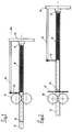
- the device has a gathering tool known per se 10, consisting of e.g. B. from two or three Roman wheels, the tubular packaging material 12 on a in this and the shirring tool 10 inserted shirring pin 14 fold in accordion-like fashion and to the rear end of the mandrel 14 against a stop attached there Slide 16 and squeeze the folds. While of the progressive gathering process will start at almost pushed to the stop 16 through the gathering tool 10 Raffdorn 14 retracted to the extent controlled as from the tubing 12 between the stop 16 and the gathering tool 10 under a certain axial Pressure-held tubular bead 18 grows in length.
- the shirring mandrel 14 with the tubular bead 18 move as far in the retraction direction after the gathering process, that the last wrinkles recede and the tubing 12 behind the gathering tool 10, where the cutting device 20 is arranged, one in occupies a substantially stretched position by the cutting member can be severed properly. If, however, the ruched Material has a very strong rebound behavior, you have the shirring mandrel 14 with the tubular bead 18 very far drive back, and the shirring pin must also be correspondingly long be to carry the expanded caterpillar 18 and the stretched portion of the tubing 12 on the Support interface.
- the one shown is Gathering device provided that at the end of the gathering process or after this at a certain distance from the front end of the shirring mandrel 14 or to the stop 16 as Holding member 22 serving fingers with a radial movement component into those generated towards the end of the gathering process Folding the tubular bead 18 retracts or swung in is, whereby it has proven to be useful to about to retract to the outside diameter of the shirring mandrel 14.
- Finger 22 is movably attached to a holder 24 in a controlled manner, which in turn attached to a support plate 26 on which the rear end of the shirring pin 14 is also mounted is.
- This connection of the holding member 22 with the shirring pin 14 over the common support plate 26 has the advantage that a single axial drive for axial advancement and Retraction of both the shirring pin 14 and the holding member 22 is enough. If so after pressing in the holding member 22 into the last created end of the tubular bead 18 the support plate 26 further withdrawn from the gathering tool 10 is, the holding member 22 also moves back and prevented the previous elastic axial expansion the tubular caterpillar 18, as the comparison between Fig. 1 and Fig. 2 shows.
- the supporting disc is 26 a turret disk with two or more The same radius is applied to the shirred thorns 14.
- the attack 16 is a slidably seated on the mandrel 14
- Trigger bushing that turns on during the gathering process the turret disk 26 is supported axially and in a later The step serves to gather the gathered tube 18 to strip from the mandrel 14.
- the support plate 26 is expedient Bracket 24 of the holding member 22 centrally on the turret appropriate.
- a fixed machine frame, engaging in the axially displaceable holder 24 Holding element prevents the holding member 22 rotates together with the turret disk 26 so that a single Holding member 22 is sufficient, which always on the respective the shirring pin 14 located in the shirring position is aligned.
- tubular caterpillar If after cutting off the shirred tube section the overpressure usually maintained therein until then is eliminated, the tubular caterpillar sits more firmly on the Raffdorn, and the tendency to expand is much lower. Therefore usually jumps at the subsequent one The tubular caterpillar does not turn the turret disk from the grub arbor. For safety's sake, however, could also be after Cut through the hose material into an easily detachable stop member attached to the front end of the shirring pin or extended, which holds back the hose material.
Landscapes
- Life Sciences & Earth Sciences (AREA)
- Engineering & Computer Science (AREA)
- Wood Science & Technology (AREA)
- Zoology (AREA)
- Food Science & Technology (AREA)
- Processing And Handling Of Plastics And Other Materials For Molding In General (AREA)
- Containers And Plastic Fillers For Packaging (AREA)
Applications Claiming Priority (2)
| Application Number | Priority Date | Filing Date | Title |
|---|---|---|---|
| DE29719179U DE29719179U1 (de) | 1997-10-29 | 1997-10-29 | Vorrichtung zum axialen Raffen von schlauchförmigem Verpackungsmaterial |
| DE29719179U | 1997-10-29 |
Publications (1)
| Publication Number | Publication Date |
|---|---|
| EP0913093A1 true EP0913093A1 (fr) | 1999-05-06 |
Family
ID=8047874
Family Applications (1)
| Application Number | Title | Priority Date | Filing Date |
|---|---|---|---|
| EP98104355A Withdrawn EP0913093A1 (fr) | 1997-10-29 | 1998-03-11 | Dispositif pour plisser axialement des boyaux tubulaires |
Country Status (2)
| Country | Link |
|---|---|
| EP (1) | EP0913093A1 (fr) |
| DE (1) | DE29719179U1 (fr) |
Families Citing this family (1)
| Publication number | Priority date | Publication date | Assignee | Title |
|---|---|---|---|---|
| DE29810056U1 (de) * | 1998-06-05 | 1998-08-27 | Drechsel, Klaus, 22846 Norderstedt | Vorrichtung zum Raffen von Umhüllungen |
Citations (5)
| Publication number | Priority date | Publication date | Assignee | Title |
|---|---|---|---|---|
| GB876285A (en) * | 1960-04-04 | 1961-08-30 | Dennis Wright Pomeroy | Devices holding sausage skins |
| EP0041149A1 (fr) * | 1980-05-31 | 1981-12-09 | Kollross, Günter | Procédé et dispositif pour huiler la surface intérieure de tubes d'emballage |
| US4773127A (en) * | 1987-11-02 | 1988-09-27 | Viskase Corporation | Method and apparatus for shirring food casings |
| US4993210A (en) * | 1989-03-08 | 1991-02-19 | Kollross Guenter | Method for packing a tubular casing length gathered into a hollow cylindrical shirring into a tubular net for subsequent processing as sausage casing in an automatic sausage-making machine |
| DE4028480A1 (de) * | 1990-09-07 | 1992-03-12 | Kollross Guenter | Verfahren und vorrichtung zur zentrierung eines kunststoffschlauchs |
-
1997
- 1997-10-29 DE DE29719179U patent/DE29719179U1/de not_active Expired - Lifetime
-
1998
- 1998-03-11 EP EP98104355A patent/EP0913093A1/fr not_active Withdrawn
Patent Citations (6)
| Publication number | Priority date | Publication date | Assignee | Title |
|---|---|---|---|---|
| GB876285A (en) * | 1960-04-04 | 1961-08-30 | Dennis Wright Pomeroy | Devices holding sausage skins |
| EP0041149A1 (fr) * | 1980-05-31 | 1981-12-09 | Kollross, Günter | Procédé et dispositif pour huiler la surface intérieure de tubes d'emballage |
| EP0041149B1 (fr) | 1980-05-31 | 1984-04-11 | Kollross, Günter | Procédé et dispositif pour huiler la surface intérieure de tubes d'emballage |
| US4773127A (en) * | 1987-11-02 | 1988-09-27 | Viskase Corporation | Method and apparatus for shirring food casings |
| US4993210A (en) * | 1989-03-08 | 1991-02-19 | Kollross Guenter | Method for packing a tubular casing length gathered into a hollow cylindrical shirring into a tubular net for subsequent processing as sausage casing in an automatic sausage-making machine |
| DE4028480A1 (de) * | 1990-09-07 | 1992-03-12 | Kollross Guenter | Verfahren und vorrichtung zur zentrierung eines kunststoffschlauchs |
Also Published As
| Publication number | Publication date |
|---|---|
| DE29719179U1 (de) | 1998-02-26 |
Similar Documents
| Publication | Publication Date | Title |
|---|---|---|
| DE3907488A1 (de) | Verfahren zum verpacken eines zu einer hohlzylindrischen raupe gerafften schlauchhuellenabschnittes in ein schlauchnetz fuer die spaetere verarbeitung als wursthuelle auf einem wurstfuellautomaten | |
| EP0025923A1 (fr) | Procédé et dispositif pour la production automatique de saucisses en chapelets en utilisant des enveloppes synthétiques comme boyaux | |
| EP0092131A2 (fr) | Dispositif de bourrage d'enveloppes tubulaires | |
| DE1532028B1 (de) | Verfahren und Vorrichtung zur Herstellung von gerafften Wursthuellen | |
| DE4111623C2 (de) | Verfahren und Vorrichtung zum maschinellen Verpacken eines auf einem Raffrohr gerafften Schlauchabschnitts | |
| EP0110341B1 (fr) | Procédé et dispositif pour ouvrir, plisser et séparer des boyaux tubulaires et pour transporter subséquemment les chenilles ainsi formées vers un autre poste de travail | |
| DD141738A5 (de) | Vorrichtung zum wickeln von spulen fuer statoren elektrischer maschinen | |
| EP0131753B1 (fr) | Procédé et dispositif pour le plissage de boyaux tubulaires | |
| DE2719717C2 (de) | Verfahren und Vorrichtung zum Ausbilden eines gasdichten oder gasdurchlässigen Endverschlusses an einem hohlzylindrischen Strang aus schlauchförmigen gerafften Häuten zur Herstellung von Wurstwaren oder dergleichen | |
| DE2511770C2 (de) | Balgartig geraffter und in ein Schlauchnetz eingeschlossener Kunstdarmschlauch | |
| DE1632139A1 (de) | Verfahren und Vorrichtung zum Kraeuseln von Wursthuellen | |
| EP0068342B1 (fr) | Unité fonctionelle pour déplisser, lisser et freiner simultanément une enveloppe tubulaire plissée | |
| DE3436616C2 (fr) | ||
| DE68915360T2 (de) | Verfahren und Vorrichtung zum Abtrennen von gefalteten Nahrungsumhüllungen. | |
| EP0913093A1 (fr) | Dispositif pour plisser axialement des boyaux tubulaires | |
| DE2902520A1 (de) | Verfahren und vorrichtung zum abteilen eines segmentes von einer laenge von gefaltetem, duennwandigem rohr | |
| DE2941872A1 (de) | Verfahren und anordnung zum automatisierten herstellen von wuersten im strang unter verwendung von synthetischem schlauchmaterial fuer die wursthuellen | |
| DE2207043B2 (de) | Verfahren zum herstellen von flachbeuteln aus thermoplastischer kunststoff- folie und vorrichtung zur durchfuehrung des verfahrens | |
| DE2950785C2 (de) | Schneidvorrichtung zum Durchschneiden eines Hohlzylinderkörpers im rechten Winkel zu seiner Längsachse | |
| DE1652771C3 (de) | Längsfahrbare Vorrichtung zum Trennen von Rohren in Abschnitte bestimmter Länge | |
| DE2646848A1 (de) | Verfahren und vorrichtung zum balgartigen raffen von kunststoffschlauch, insbesondere kunstdarm fuer die wurstherstellung | |
| DE2729572A1 (de) | Verfahren und vorrichtung zum balgartigen raffen von kunstdarm fuer die wurstherstellung auf fuellautomaten | |
| EP0143452A2 (fr) | Dispositif pour couper et enrouler des rubans en métal ou des bandes en métal | |
| DE3008739A1 (de) | Baenderzusammenklebmaschine, insbesondere fuer in kassetten zu ladende magnetbaender | |
| EP0050161B1 (fr) | Dispositif pour plisser des tubes synthétiques, notamment des boyaux artifiels pour la fabrication de saucisses |
Legal Events
| Date | Code | Title | Description |
|---|---|---|---|
| PUAI | Public reference made under article 153(3) epc to a published international application that has entered the european phase |
Free format text: ORIGINAL CODE: 0009012 |
|
| AK | Designated contracting states |
Kind code of ref document: A1 Designated state(s): AT BE CH DE DK ES FI FR GB GR IE IT LI LU MC NL PT SE |
|
| AX | Request for extension of the european patent |
Free format text: AL;LT;LV;MK;RO;SI |
|
| AKX | Designation fees paid | ||
| REG | Reference to a national code |
Ref country code: DE Ref legal event code: 8566 |
|
| STAA | Information on the status of an ep patent application or granted ep patent |
Free format text: STATUS: THE APPLICATION IS DEEMED TO BE WITHDRAWN |
|
| 18D | Application deemed to be withdrawn |
Effective date: 20001003 |