EP0913183A1 - Befestigung einer Filterdrainageschicht - Google Patents
Befestigung einer Filterdrainageschicht Download PDFInfo
- Publication number
- EP0913183A1 EP0913183A1 EP98120644A EP98120644A EP0913183A1 EP 0913183 A1 EP0913183 A1 EP 0913183A1 EP 98120644 A EP98120644 A EP 98120644A EP 98120644 A EP98120644 A EP 98120644A EP 0913183 A1 EP0913183 A1 EP 0913183A1
- Authority
- EP
- European Patent Office
- Prior art keywords
- filter element
- end cap
- drainage sleeve
- recited
- filter
- Prior art date
- Legal status (The legal status is an assumption and is not a legal conclusion. Google has not performed a legal analysis and makes no representation as to the accuracy of the status listed.)
- Withdrawn
Links
- 239000000126 substance Substances 0.000 claims description 7
- 239000000835 fiber Substances 0.000 claims description 4
- 238000004519 manufacturing process Methods 0.000 claims description 2
- 239000000356 contaminant Substances 0.000 abstract description 37
- 238000000034 method Methods 0.000 abstract description 8
- 239000000463 material Substances 0.000 description 11
- 238000001914 filtration Methods 0.000 description 9
- 230000007812 deficiency Effects 0.000 description 5
- 239000007788 liquid Substances 0.000 description 3
- 230000004048 modification Effects 0.000 description 3
- 238000012986 modification Methods 0.000 description 3
- 239000011148 porous material Substances 0.000 description 3
- 239000004593 Epoxy Substances 0.000 description 2
- 230000009471 action Effects 0.000 description 2
- 230000006978 adaptation Effects 0.000 description 2
- 238000010276 construction Methods 0.000 description 2
- 239000003292 glue Substances 0.000 description 2
- 230000005484 gravity Effects 0.000 description 2
- 239000011347 resin Substances 0.000 description 2
- 229920005989 resin Polymers 0.000 description 2
- 239000006227 byproduct Substances 0.000 description 1
- 238000004140 cleaning Methods 0.000 description 1
- 230000005574 cross-species transmission Effects 0.000 description 1
- 230000008030 elimination Effects 0.000 description 1
- 238000003379 elimination reaction Methods 0.000 description 1
- 239000006260 foam Substances 0.000 description 1
- 239000002184 metal Substances 0.000 description 1
- 230000005012 migration Effects 0.000 description 1
- 238000013508 migration Methods 0.000 description 1
- 230000037361 pathway Effects 0.000 description 1
- 229920000728 polyester Polymers 0.000 description 1
Images


Classifications
-
- B—PERFORMING OPERATIONS; TRANSPORTING
- B01—PHYSICAL OR CHEMICAL PROCESSES OR APPARATUS IN GENERAL
- B01D—SEPARATION
- B01D46/00—Filters or filtering processes specially modified for separating dispersed particles from gases or vapours
- B01D46/0027—Filters or filtering processes specially modified for separating dispersed particles from gases or vapours with additional separating or treating functions
- B01D46/003—Filters or filtering processes specially modified for separating dispersed particles from gases or vapours with additional separating or treating functions including coalescing means for the separation of liquid
- B01D46/0031—Filters or filtering processes specially modified for separating dispersed particles from gases or vapours with additional separating or treating functions including coalescing means for the separation of liquid with collecting, draining means
-
- B—PERFORMING OPERATIONS; TRANSPORTING
- B01—PHYSICAL OR CHEMICAL PROCESSES OR APPARATUS IN GENERAL
- B01D—SEPARATION
- B01D46/00—Filters or filtering processes specially modified for separating dispersed particles from gases or vapours
- B01D46/0002—Casings; Housings; Frame constructions
- B01D46/0005—Mounting of filtering elements within casings, housings or frames
-
- B—PERFORMING OPERATIONS; TRANSPORTING
- B01—PHYSICAL OR CHEMICAL PROCESSES OR APPARATUS IN GENERAL
- B01D—SEPARATION
- B01D46/00—Filters or filtering processes specially modified for separating dispersed particles from gases or vapours
- B01D46/0039—Filters or filtering processes specially modified for separating dispersed particles from gases or vapours with flow guiding by feed or discharge devices
- B01D46/0041—Filters or filtering processes specially modified for separating dispersed particles from gases or vapours with flow guiding by feed or discharge devices for feeding
- B01D46/0043—Filters or filtering processes specially modified for separating dispersed particles from gases or vapours with flow guiding by feed or discharge devices for feeding containing fixed gas displacement elements or cores
-
- B—PERFORMING OPERATIONS; TRANSPORTING
- B01—PHYSICAL OR CHEMICAL PROCESSES OR APPARATUS IN GENERAL
- B01D—SEPARATION
- B01D46/00—Filters or filtering processes specially modified for separating dispersed particles from gases or vapours
- B01D46/24—Particle separators, e.g. dust precipitators, using rigid hollow filter bodies
- B01D46/2403—Particle separators, e.g. dust precipitators, using rigid hollow filter bodies characterised by the physical shape or structure of the filtering element
- B01D46/2411—Filter cartridges
- B01D46/2414—End caps including additional functions or special forms
-
- B—PERFORMING OPERATIONS; TRANSPORTING
- B01—PHYSICAL OR CHEMICAL PROCESSES OR APPARATUS IN GENERAL
- B01D—SEPARATION
- B01D2271/00—Sealings for filters specially adapted for separating dispersed particles from gases or vapours
- B01D2271/02—Gaskets, sealings
- B01D2271/027—Radial sealings
-
- B—PERFORMING OPERATIONS; TRANSPORTING
- B01—PHYSICAL OR CHEMICAL PROCESSES OR APPARATUS IN GENERAL
- B01D—SEPARATION
- B01D2275/00—Filter media structures for filters specially adapted for separating dispersed particles from gases or vapours
- B01D2275/10—Multiple layers
-
- Y—GENERAL TAGGING OF NEW TECHNOLOGICAL DEVELOPMENTS; GENERAL TAGGING OF CROSS-SECTIONAL TECHNOLOGIES SPANNING OVER SEVERAL SECTIONS OF THE IPC; TECHNICAL SUBJECTS COVERED BY FORMER USPC CROSS-REFERENCE ART COLLECTIONS [XRACs] AND DIGESTS
- Y10—TECHNICAL SUBJECTS COVERED BY FORMER USPC
- Y10S—TECHNICAL SUBJECTS COVERED BY FORMER USPC CROSS-REFERENCE ART COLLECTIONS [XRACs] AND DIGESTS
- Y10S55/00—Gas separation
- Y10S55/13—Polyurethane filters
-
- Y—GENERAL TAGGING OF NEW TECHNOLOGICAL DEVELOPMENTS; GENERAL TAGGING OF CROSS-SECTIONAL TECHNOLOGIES SPANNING OVER SEVERAL SECTIONS OF THE IPC; TECHNICAL SUBJECTS COVERED BY FORMER USPC CROSS-REFERENCE ART COLLECTIONS [XRACs] AND DIGESTS
- Y10—TECHNICAL SUBJECTS COVERED BY FORMER USPC
- Y10S—TECHNICAL SUBJECTS COVERED BY FORMER USPC CROSS-REFERENCE ART COLLECTIONS [XRACs] AND DIGESTS
- Y10S55/00—Gas separation
- Y10S55/17—Compressed air water removal
-
- Y—GENERAL TAGGING OF NEW TECHNOLOGICAL DEVELOPMENTS; GENERAL TAGGING OF CROSS-SECTIONAL TECHNOLOGIES SPANNING OVER SEVERAL SECTIONS OF THE IPC; TECHNICAL SUBJECTS COVERED BY FORMER USPC CROSS-REFERENCE ART COLLECTIONS [XRACs] AND DIGESTS
- Y10—TECHNICAL SUBJECTS COVERED BY FORMER USPC
- Y10S—TECHNICAL SUBJECTS COVERED BY FORMER USPC CROSS-REFERENCE ART COLLECTIONS [XRACs] AND DIGESTS
- Y10S55/00—Gas separation
- Y10S55/25—Agglomerators
Definitions
- the present invention generally relates to the filtration of a contaminated gas stream. More particularly, the present invention is directed toward a filter system utilizing a modular filter element having a coalescing section which filters out and coalesces contaminants from a gas stream in order that the contaminants may drain from the filter.
- conventional filter systems utilize a filter element having an end cap positioned so that drainage of the coalesced contaminants occurs either through the end cap or along an outside edge of the end cap.
- a particular filter element currently in use includes an end cap chemically bonded to the element and having a portion located exterior to all of the remaining elements within the end cap.
- contaminants coalesce and drain from the gas stream. Through gravity, the coalesced contaminants drip into the end cap. When enough contaminants drip into the end cap, eventually the contaminants will spill over and drip down the exterior of the end cap portion.
- One deficiency is that the contaminants create a slick and messy surface on the end cap, hampering replacement of the filter element. Without a non-stick surface, removing such a filter element from a filter system is made more difficult.
- Another conventional arrangement includes a filter element having an end cap with a plurality of slots provided therein to allow for drainage of coalesced contaminants through a lower surface of the end cap.
- An example of such an arrangement may be found in United Kingdom Patent Application 2,261,830.
- the present invention alleviate the aforementioned deficiencies found in the prior art by providing a filter element of inexpensive construction which provides a drainage pathway exterior to an end cap for draining away coalesced liquids with increased flow capacity, increased efficiency or both.
- the present invention is directed to a filter system utilizing a cylindrical filter element with a filter medium for filtering out contaminants from a gas stream.
- a filter system may include a filter tank, an intake pipe, an outlet pipe and a filter vessel within which a filter element is positioned.
- the filter element is used within the system in such a way as to allow for easy removal of the filter element for replacement or cleaning.
- the filter element of the present invention includes, along with the filter medium, a filter drainage sleeve and a transport layer positioned outwardly from the medium.
- the filter element may include end caps on either end of the element, with at least one end cap having an outer circumference with an outwardly facing surface.
- the transport layer may be positioned such that it extends outwardly of at least one end cap.
- the transport layer overlays a drainage sleeve that extends up to but not over the end caps.
- the transport layer extends down over and outside the end caps.
- the filter element of the present invention may include means for attaching the drainage sleeve to the end cap at which drainage of the contaminants take place, hereinafter called the bottom cap.
- the filter element of the present invention also may incorporate a porous inner core located interior to the filter medium.
- the filter element may include a porous outer core positioned between the filter medium and the filter drainage sleeve.
- the present invention is further directed to a method of filtering a contaminated gas stream.
- This method includes the introduction of a gas stream into a filter system, passing the gas stream into a core of a tubular filter element and allowing the gas stream to pass into a coalescing section of the filter element.
- the gas stream is purified by separating the contaminants from the gas stream and coalescing them within the coalescing section.
- the method may further provide for the elimination of the contaminants from the filter elements by allowing the contaminants to drip from the lower outer most portion of the filter element into the filter system vessel, which includes a drain for draining out the contaminants.
- An object of the present invention is to provide a filter system utilizing a coalescing-type filter element.
- a system may include a filter tank, an intake pipe, an outlet pipe and a filter vessel within which such a filter element is positioned.
- the coalescing-type filter element is constructed to filter contaminants from a gas stream entering the system and remove the contaminants through a filter drainage sleeve or a transport layer positioned such that at least its lower portion is exterior to an end cap positioned there.
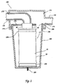
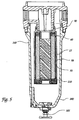
- Fig. 1 and Fig. 5 each show a preferred embodiment of a filter element 15 within filter system 160.
- filter element 15 includes a top cap 60.
- Top cap 60 has a top cap stem 90.
- a filter drainage layer 50 is included in filter element 15 .
- Drainage layer 50 has an outside transport layer, which enhances the ability of the filter to drain condensate while minimizing reentraining of the condensate.
- the transport layer 58 consists of multi-grooved fibers 580 (see Fig. 9) that are oriented in the vertical plane. The grooves act as capillaries pulling the condensate downwardly from the drain layer 50 by wicking action, draining the condensate to the bottom of the vessel 180 and then out the vessel drain 185.
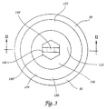
- Fig. 3 is a bottom view of a preferred embodiment of the bottom end cap 110.
- the bottom end cap 110 is completely encircled by transport layer 58 and includes a bottom cap portion 130 and a bottom cap well 112.
- Bottom cap portion 130 has a lower surface 134.
- a drainage sleeve bottom end 54 is roughly within the same plane as bottom cap portion lower surface 134, which can be better seen in Fig. 2.
- the bottom end cap 110 contains a radial projection 510 extending outward of the bottom end cap 110 resulting in an enhanced flow path for the condensate.
- filter element 15 further includes a filter medium 30 located interior to drainage sleeve 50.
- filter element 15 may include a porous inner core 20 or a porous outer core 40 or both.
- the cores 20 and 40 both provide support for the filter medium 30 as well as assist in filtering out contaminants from the gas stream.
- Inner core 20 has pores 21 and outer core 40 has pores 41.
- Both cores 20, 40 may be composed of a perforated material such as perforated metal.
- the cores 20, 40 may be composed of a mesh-like material. Such a mesh-like material may be composed of any suitable material that would lend support to the filter media 30, such as plastic and wire mesh.
- bottom cap well 112 includes an upper surface 114 and a lower surface 116.
- a bottom cap nut 140 which may include a bottom cap ring 142.
- the bottom cap ring 142 includes an aperture 144.
- the bottom cap ring 142 includes an aperture 144.
- Bottom cap ring 142 is so placed within bottom cap well 112 for easy removal of the filter element 15 from a filter system.
- bottom cap nut 140 is shown to be hexagonal in Fig. 3, the present invention is not so limited. The present invention envisions any suitable means that would allow for easy removal and replacement of filter element 15.
- the outer core 40, the filter medium 30 and the inner core 20 each have, respectively, top ends 42, 32, 22. Furthermore, the bottom ends of outer core 40, filter medium 30 and inner core 20 each have, respectively, bottom ends 44, 34, 24. Ends 22, 32, 42 are all substantially within the same plane and are adapted to receive a surface of top cap 60. Likewise, bottom ends 24, 34, 44 are all substantially within the same plane and are adapted to receive a surface of bottom cap 110.
- Inner core 20 further includes an inside surface 26 and an outside surface 28. The inside surface 26 of inner core 20 is adjacent to and may abut a surface of top cap 60 as well as a surface of bottom cap 110. Outside surface 28 of inner core 20 faces inside surface 36 of filter medium 30. Outer core 40 further has an inside surface 46 which faces outside surface 38 of filter medium 30. In addition, outer core 40 has an outside surface 48 which faces drainage layer inside surface 56.
- Top cap 60 includes a stem 90 and may include an inner projection 62 and an outer projection 70.
- Inner projection 62 includes an inside surface 64 and an outside surface 66. Outside surface 66 faces inner core inside surface 26.
- Top cap outer projection 70 further includes a lower surface 71, an inside surface 72 and an outside surface 78. Inside surface 72 faces outer core outside surface 48.
- Top cap outer projection outside surface 78 may further include an upper lip 74 and a lower lip 76.
- Top cap portion 80 is located in a plane roughly perpendicular to projections 62, 70.
- Portion 80 includes an upper surface 82 and a lower surface 84.
- Lower surface 84 abuts top ends 22, 32, 42 of inner core 20, filter medium 30 and outer core 40.
- Lower surface 84 may further include surface ridges 86. Ridges 86 may enhance attachment of surface 84 of top cap 60 to top ends 22, 32, 42 through a chemical bond, such as epoxy, resin or glue applied thereon.
- Surface 82 of top cap portion 80 is roughly within the same plane as a filter drainage sleeve top end 52 of drainage sleeve 50.
- an intake 100 Located throughout end cap 60 and contiguous with top cap inside surface 92 is an intake 100. As shown in Fig. 3, a threaded intake opening 102 is located at the uppermost portion of top cap 60 and may be used to connect the filter element 15 to an intake pipe 162 of filter system 160 (described in greater detail below).
- Bottom cap portion 130 includes a lower surface 134 and an upper surface 132.
- Upper surface 132 abuts against bottom ends 24, 34, 44 of inner core 20, filter medium 30, and outer core 40, respectively.
- Upper surface 132 may further include ridges 136 which function similarly to top cap lower surface ridges 86 described above.
- Bottom cap 110 may further include an outer projection 120.
- Outer projection 120 includes an upper surface 121 and an inside surface 122, which faces outer core outside surface 48.
- Outer projection 120 also includes an outside surface 128, which faces filter drainage sleeve inside surface 56.
- Outside surface 128 may further include an upper lip 124 and a lower lip 126.
- bottom cap 110 includes bottom cap well upper surface 114. This well upper surface 114 prevents the gas stream that flows into filter element 15 through intake 100 from flowing out of filter element 15 through bottom cap 110.
- filter element 215 is of similar construction to filter element 15.
- Filter element drainage sleeve 250 is disposed outwardly from outer core 40. Drainage sleeve 250 extends along the length of outer core 40 like drainage sleeve 50. Unlike drainage sleeve 50, sleeve 250 stops short of top cap outer projection lower surface 71 and bottom cap outer projection upper surface 121. Alternatively, drainage sleeve 250 may terminate by abutting top cap outer projection lower surface 71 and bottom cap outer projection upper surface 121.
- Transport layer 252 is formed of a material allowing contaminants to travel therethrough and may be formed of the same or similar material as drainage sleeves 50, 250. As shown in Fig. 4, transport layer 252 is disposed exterior to drainage sleeve 250. Transport layer 252 extends the length of outer core 40 and terminates with its top end 254 roughly in the same plane as top cap portion upper surface 82 and its bottom end 256 roughly in the same plane as bottom cap portion lower surface 134.
- Transport layer 252 may be attached to caps 60, 110 by way of mechanical and/or chemical bonds, as discussed above in regard to drainage sleeve 50 of filter element 15.
- constriction bands 150 or another suitable mechanical bond, may be used to attach transport layer 252 to caps 60, 110.
- any suitable chemical bond such as epoxy, resin or glue, may be used, alone or in concert with a mechanical bond, to attach transport layer 252 to caps 60, 110.
- Drainage sleeve 50, transport layer 252 and constriction bands 150 may be colorized so as to provide color coding for specific sizes and types of filter elements 15, 215. Further, drainage sleeve 50, transport layer 252 and constriction bands 150 may be formed of a material capable of receiving a marking, such marking to identify the filter element 15, 215 by product number, company name and/or by trademark, logo or the like.
- Fig. 1 shows a preferred embodiment of a filter system 160 which utilizes a filter element 15. It is to be understood that filter element 215 may also be utilized within the filter system 160.
- Filter system 160 includes a filter system intake pipe 162, a filter system outlet pipe 164, a filter tank 170 and a filter vessel 180. Intake pipe 162 enters tank 170 at tank intake 172 and proceeds into filter element intake 100 (Fig. 2) of stem 90 within top cap 60. Filter system outlet pipe 164 exits from filter system 160 at filter tank outlet 174.
- Filter vessel 180 is attachable to and removable from filter tank 170. Filter vessel 180 creates a seal 176 between itself and filter tank 170 when properly attached. The seal 176 prevents the escape of the gas stream from the filter system 160. Vessel 180 also includes an outlet 184 into tank 170 to allow the gas stream exiting filter element 15 to flow into outlet pipe 164. Vessel 180 further includes a vessel drain 185 located at a bottom portion of vessel 180. As can be seen in Fig. 1, the lowest portion of vessel 180 may slope downwardly toward vessel drain 185. The drain 185 is positioned in order to allow contaminants which are filtered out of the gas stream to exit the filter system 160.
- a filter element 15 is attached to a filter tank intake 172 of filter system 160.
- a gas stream passes into filter system 160 by way of intake pipe 162, which leads into filter tank intake 172.
- the gas stream which is contaminated with various particulates, passes into filter element 15 through top cap 60.
- the gas stream passes through the intake 100 and into inner core 20. Due to bottom cap well upper surface 114, the gas stream is prevented from passing out of filter element 15 through bottom cap 110. Instead, the contaminated gas stream is directed through pores 21 in inner core 20.
- the contaminated gas stream then passes into the outwardly situated filter medium 30.
- This filter medium is a coalescing type of medium. As the gas stream passes through filter medium 30, the particulates and other contaminants are separated out. As the particulates and other contaminants separate out, they coalesce within the filter medium 30.
Landscapes
- Chemical & Material Sciences (AREA)
- Chemical Kinetics & Catalysis (AREA)
- Physics & Mathematics (AREA)
- Geometry (AREA)
- Filtering Of Dispersed Particles In Gases (AREA)
- Filtering Materials (AREA)
- Filtration Of Liquid (AREA)
Applications Claiming Priority (2)
| Application Number | Priority Date | Filing Date | Title |
|---|---|---|---|
| US08/963,274 US5961678A (en) | 1995-07-07 | 1997-11-03 | Filter drainage layer attachment |
| US963274 | 2001-09-26 |
Publications (1)
| Publication Number | Publication Date |
|---|---|
| EP0913183A1 true EP0913183A1 (de) | 1999-05-06 |
Family
ID=25507000
Family Applications (1)
| Application Number | Title | Priority Date | Filing Date |
|---|---|---|---|
| EP98120644A Withdrawn EP0913183A1 (de) | 1997-11-03 | 1998-11-03 | Befestigung einer Filterdrainageschicht |
Country Status (6)
| Country | Link |
|---|---|
| US (1) | US5961678A (de) |
| EP (1) | EP0913183A1 (de) |
| JP (1) | JPH11197426A (de) |
| KR (1) | KR19990044969A (de) |
| AU (1) | AU731091B2 (de) |
| CA (1) | CA2253162A1 (de) |
Cited By (5)
| Publication number | Priority date | Publication date | Assignee | Title |
|---|---|---|---|---|
| WO2008092261A1 (en) * | 2007-02-02 | 2008-08-07 | Prosep Inc. | Cylindrical cartridge assembly with interlocking wall panels |
| WO2008125885A2 (en) | 2007-04-16 | 2008-10-23 | Psi Global Ltd | Improvements in coalescing filters |
| EP3078405A1 (de) * | 2015-04-06 | 2016-10-12 | Pall Corporation | Filterelemente |
| EP2559471A3 (de) * | 2011-08-18 | 2016-12-07 | BHA Altair, LLC | Filterkern zur Verwendung mit gefalteten Filterpatronen |
| US12478909B2 (en) | 2021-03-18 | 2025-11-25 | China University Of Petroleum-Beijing | Coalescing filter element |
Families Citing this family (46)
| Publication number | Priority date | Publication date | Assignee | Title |
|---|---|---|---|---|
| GB2335867A (en) * | 1998-04-03 | 1999-10-06 | Process Scient Innovations | Thermally bonded felt material for coalescence filters |
| US6635114B2 (en) * | 1999-12-17 | 2003-10-21 | Applied Material, Inc. | High temperature filter for CVD apparatus |
| DE10052524A1 (de) * | 2000-10-23 | 2002-04-25 | Beko Technologies Gmbh | Filter zum Abscheiden von Fremdstoffen aus einem Gasstrom |
| US6798136B2 (en) * | 2001-06-19 | 2004-09-28 | Gelcore Llc | Phosphor embedded die epoxy and lead frame modifications |
| US6632352B2 (en) * | 2001-07-11 | 2003-10-14 | Nursery Pro, Inc. | Multi-stage filter |
| US7374673B2 (en) * | 2001-09-10 | 2008-05-20 | Clemson University | Channeled polymer fibers as stationary/support phases for chemical separation by liquid chromatography and for waste stream clean-up |
| US20070071649A1 (en) * | 2001-09-10 | 2007-03-29 | Marcus R Kenneth | Capillary-channeled polymer fibers as stationary phase media for spectroscopic analysis |
| US6596043B1 (en) | 2001-10-17 | 2003-07-22 | Nelson Industries, Inc. | Air/oil separator tank with permanent drain layer |
| DE102004022312B4 (de) * | 2004-05-04 | 2009-04-16 | Daimler Ag | Feuchtigkeitsaustauschmodul mit einem Bündel von für Feuchtigkeit durchlässigen Hohlfasermembranen |
| SE527255C2 (sv) | 2004-06-17 | 2006-01-31 | Absolent Ab | Filtermatta försedd med vekar för avlägsnande av absorberande aerosoler |
| DE102004029225A1 (de) | 2004-06-17 | 2006-01-12 | Hydac Filtertechnik Gmbh | Filtervorrichtung und Filterelement |
| ATE542588T1 (de) * | 2004-08-05 | 2012-02-15 | Parker Hannifin Ltd | Filterbaugruppe |
| GB0417459D0 (en) * | 2004-08-05 | 2004-09-08 | Domnick Hunter Ltd | Filter assembly |
| GB0417458D0 (en) * | 2004-08-05 | 2004-09-08 | Domnick Hunter Ltd | Filter assembly |
| GB0417455D0 (en) * | 2004-08-05 | 2004-09-08 | Domnick Hunter Ltd | Filter element |
| GB0417464D0 (en) | 2004-08-05 | 2004-09-08 | Domnick Hunter Ltd | Filter assembly |
| US7740763B2 (en) | 2004-08-10 | 2010-06-22 | Clemson University | Capillary-channeled polymeric fiber as solid phase extraction media |
| US7261813B2 (en) * | 2004-08-10 | 2007-08-28 | Clemson University | Monolithic structures comprising polymeric fibers for chemical separation by liquid chromatography |
| US7384455B2 (en) * | 2004-10-05 | 2008-06-10 | Caterpillar Inc. | Filter service system and method |
| US7419532B2 (en) * | 2004-10-05 | 2008-09-02 | Caterpillar Inc. | Deposition system and method |
| US7462222B2 (en) * | 2004-10-05 | 2008-12-09 | Caterpillar Inc. | Filter service system |
| US7410529B2 (en) | 2004-10-05 | 2008-08-12 | Caterpillar Inc. | Filter service system and method |
| US7387656B2 (en) * | 2005-01-07 | 2008-06-17 | Mecs, Inc. | Fiber collecting media strip for a mist eliminator |
| RU2287358C1 (ru) * | 2005-06-08 | 2006-11-20 | Николай Яковлевич ЗАЙЦЕВ | Фильтр-сепарационный элемент для очистки и осушки газов |
| JP4638329B2 (ja) * | 2005-11-09 | 2011-02-23 | 株式会社ケーヒン | 気体用液体トラップ装置 |
| US7416576B2 (en) * | 2006-01-27 | 2008-08-26 | Mecs, Inc. | Fiber bed assembly and fiber bed therefor |
| US7927394B2 (en) * | 2006-05-31 | 2011-04-19 | Gas Liquids Engineering Ltd. | Apparatus and method for enhanced droplet collection in gas flows |
| RU2311944C1 (ru) * | 2006-06-30 | 2007-12-10 | Федеральное государственное унитарное предприятие "Электростальское научно-производственное объединение "Неорганика" (ФГУП "ЭНПО "Неорганика") | Фильтр для очистки природного газа |
| DE202006011990U1 (de) * | 2006-08-03 | 2007-12-20 | Mann + Hummel Gmbh | Filtereinheit mit einem radial geteilten Gehäuse |
| JP4674586B2 (ja) * | 2007-01-15 | 2011-04-20 | パナソニック株式会社 | エアフィルタ清掃装置 |
| US8152887B2 (en) * | 2008-12-15 | 2012-04-10 | Mann + Hummel Gmbh | Air/oil separator |
| AU2015221505B2 (en) * | 2009-09-08 | 2017-02-02 | Mecs, Inc. | A fiber bed assembly for a fiber bed mist eliminator |
| US8636819B2 (en) * | 2009-09-08 | 2014-01-28 | Mecs, Inc. | Fiber bed assembly for a fiber bed mist eliminator |
| US8632616B2 (en) * | 2009-09-08 | 2014-01-21 | Mecs, Inc. | Fiber bed assembly for a fiber bed mist eliminator |
| DE102010009268A1 (de) * | 2010-02-25 | 2011-08-25 | MAHLE International GmbH, 70376 | Filterelement und Filtereinrichtung |
| RU2469771C1 (ru) * | 2011-06-29 | 2012-12-20 | Общество с ограниченной ответственностью "Инженерно-внедренческий центр "ИНЖЕХИМ" | Сепаратор для очистки газа |
| RU2472570C1 (ru) * | 2011-11-16 | 2013-01-20 | Общество с ограниченной ответственностью "Инженерно-внедренческий центр "ИНЖЕХИМ" | Сепаратор для очистки газа |
| WO2015079394A1 (en) | 2013-11-27 | 2015-06-04 | Atlas Copco Airpower N.V. | High bulk coalescing filter media and use thereof |
| US9759057B2 (en) * | 2014-04-11 | 2017-09-12 | Dynacorp Fabricators Inc. | Apparatus, system and method for separating sand and other solids from oil and other fluids |
| EP2946822A1 (de) * | 2014-05-22 | 2015-11-25 | Linde Aktiengesellschaft | Trenneinrichtung zum Trennen einer gasförmigen von einer flüssigen Phase eines zweiphasigen Stoffstromes |
| AT516310B1 (de) * | 2014-09-15 | 2016-06-15 | Ge Jenbacher Gmbh & Co Og | Filtereinsatz |
| AT14696U1 (de) * | 2014-09-15 | 2016-04-15 | Ge Jenbacher Gmbh & Co Og | Filter |
| WO2019010671A1 (en) * | 2017-07-13 | 2019-01-17 | Mann+Hummel Gmbh | SEPARATION DEVICE AND OIL SEPARATION AIR FILTER ASSEMBLY COMPRISING SUCH A SEPARATION DEVICE AND METHOD OF SEPARATING FLUID FROM A GAS FLOW FROM A CONNECTING DEVICE |
| EP3804834B1 (de) * | 2018-05-30 | 2024-03-06 | NC Engenharia Indústria E Comércio LTDA | Vorrichtung zum entleeren und abdichten eines tropfenabscheiders |
| US20230039778A1 (en) * | 2021-08-05 | 2023-02-09 | Hamilton Sundstrand Corporation | Passive phase separator at a heat exchanger output |
| US12172113B2 (en) * | 2024-07-30 | 2024-12-24 | Zhejiang Nan Pu Pneumatic Component Co., Ltd. | Air filter |
Citations (2)
| Publication number | Priority date | Publication date | Assignee | Title |
|---|---|---|---|---|
| US5496627A (en) * | 1995-06-16 | 1996-03-05 | Eastman Chemical Company | Composite fibrous filters |
| EP0752262A1 (de) * | 1995-07-07 | 1997-01-08 | Flair Corporation | Befestigung einer Filterdrainageschicht |
Family Cites Families (54)
| Publication number | Priority date | Publication date | Assignee | Title |
|---|---|---|---|---|
| US2334840A (en) * | 1940-06-29 | 1943-11-23 | Mine Safety Appliances Co | Canister |
| NL86719C (de) * | 1951-12-17 | |||
| BE578628A (de) * | 1958-05-14 | |||
| US3085381A (en) * | 1960-05-25 | 1963-04-16 | Rockwell Standard Co | Two-stage oil separator |
| US3290870A (en) * | 1963-11-21 | 1966-12-13 | Walker Mfg Co | Disposable air filter for internal combustion engines |
| US3308610A (en) * | 1964-03-31 | 1967-03-14 | Robbins & Myers | Fluid apparatus for removing mist or vapors from the air |
| US3352423A (en) * | 1965-04-08 | 1967-11-14 | Filters Inc | Filter and coalescer element |
| US3450632A (en) * | 1967-05-03 | 1969-06-17 | Chevron Res | Method for simultaneously coalescing,filtering and removing oil traces from liquids and media for accomplishing the same |
| BE719504A (de) * | 1967-08-17 | 1969-01-16 | ||
| US3517820A (en) * | 1968-03-15 | 1970-06-30 | Purolator Products Inc | Coalescer cartridge |
| US3567619A (en) * | 1968-06-03 | 1971-03-02 | Us Army | Electrostatic coalescence means |
| US3890123A (en) * | 1969-05-19 | 1975-06-17 | Shoketsu Kinzoku Kogyo Kk | Mist separator |
| US3708965A (en) * | 1970-09-08 | 1973-01-09 | K Domnick | Gas filters |
| US3800945A (en) * | 1971-11-26 | 1974-04-02 | Cata Sep Inc | Cell having catalytic action for coalescing oil droplets |
| US3802160A (en) * | 1972-05-17 | 1974-04-09 | Hankison Corp | Aerosol coalescing filter and the like |
| US3931019A (en) * | 1973-10-23 | 1976-01-06 | Products And Pollution Controls Co. | Reinforced coalescing cell |
| US4050237A (en) * | 1974-03-11 | 1977-09-27 | Pall Corporation | Demister assembly for removing liquids from gases |
| US4086070A (en) * | 1975-12-22 | 1978-04-25 | Monsanto Company | Fiber bed separator and method for separation of aerosols from gases without re-entrainment |
| US3997305A (en) * | 1976-03-05 | 1976-12-14 | Flex-Kleen Corporation | Support for bottom removal dust collector bag assembly |
| GB1544822A (en) * | 1976-03-26 | 1979-04-25 | Process Scient Innovations | Filter elements for gas or liquid and methods of making such elements |
| GB1566264A (en) * | 1976-04-23 | 1980-04-30 | Whatman Reeve Angel Ltd | Inside-to-outside flow filter tube and method of manufacturing same |
| FR2363355A1 (fr) * | 1976-09-07 | 1978-03-31 | Europ Accumulateurs | Filtre a gaz a element filtrant encliquetable |
| GB1574014A (en) * | 1976-12-24 | 1980-09-03 | Whatman Reeve Angel Ltd | Filter tubes |
| DE2706017A1 (de) * | 1977-02-12 | 1978-08-17 | Ultrafilter Gmbh | Filterelement |
| US4136009A (en) * | 1977-11-17 | 1979-01-23 | David Samiran | Adjustable float and filter assembly |
| GB2033247B (en) * | 1978-10-18 | 1982-11-03 | Process Scient Innovations | Filter silencer for compressed gas stream |
| CA1122906A (en) * | 1979-04-06 | 1982-05-04 | James P. Donachiue | Air prefilter |
| US4249918A (en) * | 1979-05-21 | 1981-02-10 | Monsanto Company | Fiber bed element and process for removing aerosols from gases |
| DE2931702A1 (de) * | 1979-08-04 | 1981-02-19 | Kernforschungsz Karlsruhe | Tropfenabscheider zum abscheiden von fluessigkeitstropfen aus gas- bzw. dampfstroemen |
| JPS5676017U (de) * | 1979-11-13 | 1981-06-20 | ||
| US4385913A (en) * | 1981-11-27 | 1983-05-31 | Lane Arlo E | Device for eliminating droplets of liquid from a gas stream |
| US4487618A (en) * | 1982-08-19 | 1984-12-11 | La-Man Corporation | Airline vapor trap |
| US4477270A (en) * | 1983-01-07 | 1984-10-16 | Franz Tauch | Air filter |
| US4487617A (en) * | 1983-08-22 | 1984-12-11 | The Bendix Corporation | Mechanism for cleaning and drying compressed gases |
| US4878930A (en) * | 1984-03-15 | 1989-11-07 | W. L. Gore & Associates, Inc. | Filter cartridge |
| US4516994A (en) * | 1984-04-11 | 1985-05-14 | Vilter Manufacturing Corporation | Apparatus for separating liquid droplets from gas |
| US4600416A (en) * | 1985-02-08 | 1986-07-15 | La-Man Corporation | Air line vapor trap |
| US4676807A (en) * | 1985-07-05 | 1987-06-30 | Pall Corporation | Process for removal of liquid aerosols from gaseous streams |
| US4759782A (en) * | 1985-07-05 | 1988-07-26 | Pall Corporation | Coalescing filter for removal of liquid aerosols from gaseous streams |
| US4976759A (en) * | 1986-07-14 | 1990-12-11 | Hankison Corporation | Filter |
| US4838903A (en) * | 1987-05-20 | 1989-06-13 | Ceco Filters, Inc. | Multi-phase thick-bed filter |
| US4767426A (en) * | 1987-10-05 | 1988-08-30 | Whatman Reeve Angel Plc | Membrane filter tube and method of preparation |
| US4915714A (en) * | 1988-06-23 | 1990-04-10 | Teague Richard K | Fiber bed element and process for removing small particles of liquids and solids from a gas stream |
| DE8808333U1 (de) * | 1988-06-29 | 1988-08-25 | Durst, Matthias | Filtergerät |
| US5002593A (en) * | 1989-02-22 | 1991-03-26 | Nippon Air Brake Co., Ltd. | Compressed-air dryer |
| US5066318A (en) * | 1990-04-13 | 1991-11-19 | Pcf Group, Inc. | Filter element gasket |
| US5336405A (en) * | 1990-04-20 | 1994-08-09 | Minnesota Mining And Manufacturing Company | Filter cartridge end cap assembly |
| US5082476A (en) * | 1990-10-19 | 1992-01-21 | Donaldson Company, Inc. | Filtration arrangement and method |
| GB2261830B (en) * | 1991-11-26 | 1995-07-26 | Process Scient Innovations | Filter for purification of gas |
| US5605748A (en) * | 1993-01-22 | 1997-02-25 | Monsanto Enviro-Chem Systems, Inc. | Fiber beds for fiber bed mist eliminators |
| US5350515A (en) * | 1993-03-29 | 1994-09-27 | W. L. Gore & Associates, Inc. | Internally potted end cap for a pleated filter medium |
| CA2097274C (en) * | 1993-05-28 | 1999-08-24 | Darrel Sutton | Extended surface pocket type air filter |
| JP2792526B2 (ja) * | 1993-07-12 | 1998-09-03 | 和興産業株式会社 | 親水性不純物の除去装置および除去方法およびフェノール製造装置 |
| US5415676A (en) * | 1993-08-16 | 1995-05-16 | Donaldson Company, Inc. | Mist collector cartridge |
-
1997
- 1997-11-03 US US08/963,274 patent/US5961678A/en not_active Expired - Fee Related
-
1998
- 1998-11-02 CA CA002253162A patent/CA2253162A1/en not_active Abandoned
- 1998-11-03 KR KR1019980046929A patent/KR19990044969A/ko not_active Withdrawn
- 1998-11-03 EP EP98120644A patent/EP0913183A1/de not_active Withdrawn
- 1998-11-03 AU AU90507/98A patent/AU731091B2/en not_active Ceased
- 1998-11-04 JP JP10313200A patent/JPH11197426A/ja active Pending
Patent Citations (3)
| Publication number | Priority date | Publication date | Assignee | Title |
|---|---|---|---|---|
| US5496627A (en) * | 1995-06-16 | 1996-03-05 | Eastman Chemical Company | Composite fibrous filters |
| EP0752262A1 (de) * | 1995-07-07 | 1997-01-08 | Flair Corporation | Befestigung einer Filterdrainageschicht |
| EP0752263A1 (de) * | 1995-07-07 | 1997-01-08 | Flair Corporation | Befestigung für Filterverschlusskappe |
Cited By (7)
| Publication number | Priority date | Publication date | Assignee | Title |
|---|---|---|---|---|
| WO2008092261A1 (en) * | 2007-02-02 | 2008-08-07 | Prosep Inc. | Cylindrical cartridge assembly with interlocking wall panels |
| WO2008125885A2 (en) | 2007-04-16 | 2008-10-23 | Psi Global Ltd | Improvements in coalescing filters |
| WO2008125885A3 (en) * | 2007-04-16 | 2008-12-04 | Psi Global Ltd | Improvements in coalescing filters |
| EP2559471A3 (de) * | 2011-08-18 | 2016-12-07 | BHA Altair, LLC | Filterkern zur Verwendung mit gefalteten Filterpatronen |
| EP3078405A1 (de) * | 2015-04-06 | 2016-10-12 | Pall Corporation | Filterelemente |
| US9579592B2 (en) | 2015-04-06 | 2017-02-28 | Pall Corporation | Filter elements |
| US12478909B2 (en) | 2021-03-18 | 2025-11-25 | China University Of Petroleum-Beijing | Coalescing filter element |
Also Published As
| Publication number | Publication date |
|---|---|
| AU731091B2 (en) | 2001-03-22 |
| AU9050798A (en) | 1999-05-20 |
| CA2253162A1 (en) | 1999-05-03 |
| JPH11197426A (ja) | 1999-07-27 |
| KR19990044969A (ko) | 1999-06-25 |
| US5961678A (en) | 1999-10-05 |
Similar Documents
| Publication | Publication Date | Title |
|---|---|---|
| EP0913183A1 (de) | Befestigung einer Filterdrainageschicht | |
| US10898836B2 (en) | Filter with exterior and interior media components and method of filtering | |
| US6797025B2 (en) | Conically shaped air-oil separator | |
| US4058463A (en) | Element for filtering and separating fluid mixtures | |
| US6322697B1 (en) | Oil filter assembly | |
| US5454945A (en) | Conical coalescing filter and assembly | |
| US6093231A (en) | Air/oil separator with unitary top end cap and flange | |
| EP3928849B1 (de) | Filteranordnung mit vorfiltrierungsfilterelement und filtervorrichtung | |
| US5725621A (en) | Filter end cap attachment | |
| US7314555B2 (en) | Filter cartridge for a filter assembly | |
| GB2138693A (en) | Filter Cartridge | |
| US7897046B2 (en) | Fluid filter | |
| EP0752262A1 (de) | Befestigung einer Filterdrainageschicht | |
| AU665211B2 (en) | Conical coalescing filter | |
| US20040149647A1 (en) | Filter element flow diverter barrier and method | |
| AU711894B2 (en) | Filter drainage layer attachment | |
| JP2000508581A (ja) | 使い捨てコアレッサー | |
| US20040020871A1 (en) | Method of filtering fluids | |
| MXPA96002627A (es) | Aparato en capas de desagüe filtrante |
Legal Events
| Date | Code | Title | Description |
|---|---|---|---|
| PUAI | Public reference made under article 153(3) epc to a published international application that has entered the european phase |
Free format text: ORIGINAL CODE: 0009012 |
|
| AK | Designated contracting states |
Kind code of ref document: A1 Designated state(s): AT BE DE ES FR GB IT NL |
|
| AX | Request for extension of the european patent |
Free format text: AL;LT;LV;MK;RO;SI |
|
| 17P | Request for examination filed |
Effective date: 19990702 |
|
| AKX | Designation fees paid |
Free format text: AT BE DE ES FR GB IT NL |
|
| 17Q | First examination report despatched |
Effective date: 20021018 |
|
| STAA | Information on the status of an ep patent application or granted ep patent |
Free format text: STATUS: THE APPLICATION IS DEEMED TO BE WITHDRAWN |
|
| 18D | Application deemed to be withdrawn |
Effective date: 20030301 |