EP0913209A2 - Apparat und Verfahren zur Ultraschallreinigung - Google Patents
Apparat und Verfahren zur Ultraschallreinigung Download PDFInfo
- Publication number
- EP0913209A2 EP0913209A2 EP98308841A EP98308841A EP0913209A2 EP 0913209 A2 EP0913209 A2 EP 0913209A2 EP 98308841 A EP98308841 A EP 98308841A EP 98308841 A EP98308841 A EP 98308841A EP 0913209 A2 EP0913209 A2 EP 0913209A2
- Authority
- EP
- European Patent Office
- Prior art keywords
- ultrasonic
- thickness
- wall
- ultrasonic frequency
- transducers
- Prior art date
- Legal status (The legal status is an assumption and is not a legal conclusion. Google has not performed a legal analysis and makes no representation as to the accuracy of the status listed.)
- Withdrawn
Links
- 238000004506 ultrasonic cleaning Methods 0.000 title claims abstract description 47
- 238000000034 method Methods 0.000 title claims description 10
- 238000004140 cleaning Methods 0.000 claims description 29
- 230000005540 biological transmission Effects 0.000 claims description 9
- 230000002939 deleterious effect Effects 0.000 abstract description 5
- 239000000356 contaminant Substances 0.000 description 6
- 230000003628 erosive effect Effects 0.000 description 5
- 238000010276 construction Methods 0.000 description 4
- 239000012530 fluid Substances 0.000 description 3
- 239000000463 material Substances 0.000 description 3
- 239000002245 particle Substances 0.000 description 2
- 229910001220 stainless steel Inorganic materials 0.000 description 2
- 239000010935 stainless steel Substances 0.000 description 2
- 238000003466 welding Methods 0.000 description 2
- 239000012790 adhesive layer Substances 0.000 description 1
- 239000002826 coolant Substances 0.000 description 1
- 230000007797 corrosion Effects 0.000 description 1
- 238000005260 corrosion Methods 0.000 description 1
- 238000013461 design Methods 0.000 description 1
- 230000003292 diminished effect Effects 0.000 description 1
- 238000003754 machining Methods 0.000 description 1
- 230000007257 malfunction Effects 0.000 description 1
- 239000002184 metal Substances 0.000 description 1
- 239000003921 oil Substances 0.000 description 1
Images



Classifications
-
- B—PERFORMING OPERATIONS; TRANSPORTING
- B08—CLEANING
- B08B—CLEANING IN GENERAL; PREVENTION OF FOULING IN GENERAL
- B08B3/00—Cleaning by methods involving the use or presence of liquid or steam
- B08B3/04—Cleaning involving contact with liquid
- B08B3/10—Cleaning involving contact with liquid with additional treatment of the liquid or of the object being cleaned, e.g. by heat, by electricity or by vibration
- B08B3/12—Cleaning involving contact with liquid with additional treatment of the liquid or of the object being cleaned, e.g. by heat, by electricity or by vibration by sonic or ultrasonic vibrations
Definitions
- the present invention relates generally to ultrasonic cleaning apparatus and method and pertains, more specifically, to ultrasonic cleaning apparatus and method in which ultrasonic cleaning of articles is carried out in a bath to which ultrasonic energy of different frequencies is provided simultaneously for accomplishing cleaning of the articles.
- Ultrasonic cleaning systems have found widespread use in the cleaning of manufactured parts.
- various industrial contaminants, such as drawing oils, coolants, and particulates have been removed successfully from manufactured parts by immersing the parts in a bath to which ultrasonic energy is provided for accomplishing cleaning of the parts.
- Current ultrasonic cleaning systems employ piezoelectric ultrasonic transducers mounted to the bottom of a tank containing a fluid bath within which the articles to be cleaned are immersed. The transducers are powered and the bottom of the tank serves as a vibratory diaphragm through which ultrasonic energy emanating from the transducers is transmitted to the bath for accomplishing cleaning of the articles.
- the ultrasonic transducers employed in ultrasonic cleaning systems are made available in various ultrasonic frequencies, with each frequency providing specific cleaning characteristics and properties. Generally, lower frequencies are more efficient in removing larger particles from articles being cleaned, while higher frequencies are more effective for removing submicronic particulates. Users of ultrasonic cleaning equipment usually determine which frequency is best suited to the needs of a particular cleaning operation and choose the systems most appropriate to those needs. However, in some instances, the range of sizes of particles to be removed is quite wide and an ultrasonic cleaning system operating at a single ultrasonic frequency is not as effective as desired.
- contaminants are adhered to the articles to be cleaned with such tenacity that there is a need for the added power available in low-frequency ultrasonic energy to dislodge such contaminants, while the characteristics of high-frequency ultrasonic energy are needed to deal with submicronic contaminants which also are present.
- ultrasonic cleaning machines have been constructed with ultrasonic transducers of one selected frequency coupled to one cleaning tank. Any requirement for accomplishing ultrasonic cleaning at different frequencies has been attained by utilizing separate cleaning tanks powered by separate ultrasonic transducers of different frequencies. It had been thought that ultrasonic transducers of different ultrasonic frequencies, mounted side-by-side upon the same tank, and thus coupled to a common vibratory diaphragm, would interfere with one another with the result that, at the very least, cleaning effectiveness would be very much diminished or, at worst, the transducers would be destroyed. Accordingly, ultrasonic cleaning machines have been limited to mounting only transducers of a single frequency on a particular cleaning tank.
- the present invention provides ultrasonic cleaning apparatus and method which utilizes ultrasonic energy of different frequencies for attaining the benefits provided by the different frequencies, while avoiding the deleterious effects outlined above.
- the present invention attains several objects and advantages, some of which are summarized as follows: Enables ultrasonic cleaning of articles through the simultaneous utilization of both low and high frequency ultrasonic energy for more effective ultrasonic cleaning; provides simplified ultrasonic cleaning apparatus in that a single cleaning tank is employed for cleaning with multiple frequency ultrasonic energy utilized simultaneously for efficient ultrasonic cleaning of articles; attains more effective ultrasonic cleaning in less time and with less energy than heretofore accomplished with conventional ultrasonic cleaning apparatus and methods; provides a more uniform ultrasonic energy field throughout an ultrasonic cleaning bath for more efficient cleaning of articles placed in the bath; reduces the time required for completing ultrasonic cleaning operations; increases the reliability and the service life of ultrasonic cleaning apparatus.
- the present invention which may be described briefly as an improvement in ultrasonic cleaning apparatus in which articles to be cleaned are immersed in a bath subjected to ultrasonic energy emanating from ultrasonic transducers coupled to a wall contiguous with the bath, the improvement comprising: first transducers for providing ultrasonic energy at a first ultrasonic frequency; and second transducers for providing ultrasonic energy at a second ultrasonic frequency different from the first ultrasonic frequency; the first transducers being interspersed with the second transducers, with the first transducers being placed at first locations along the wall and the second transducers being placed at second locations along the wall, each first location being spaced from an adjacent second location a distance enabling the first and second transducers simultaneously to transmit to the bath ultrasonic energy at the respective first and second ultrasonic frequencies to accomplish effective cleaning of the articles immersed in the bath.
- the invention further includes an improvement in an ultrasonic cleaning method in which articles to be cleaned are immersed in a bath subjected to ultrasonic energy emanating from locations along a wall contiguous with the bath, the improvement comprising: providing ultrasonic energy at first locations along the wall at a first ultrasonic frequency; and providing ultrasonic energy at second locations along the wall at a second ultrasonic frequency different from the first ultrasonic frequency; the first locations being interspersed with the second locations, with each first location being spaced from an adjacent second location a distance enabling simultaneous transmission to the bath of ultrasonic energy at the respective first and second ultrasonic frequencies to accomplish effective cleaning of the articles immersed in the bath.
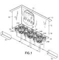
- an ultrasonic cleaning apparatus constructed in accordance with the present invention is shown at 10 and is seen to include a cleaning tank 12 containing a cleaning bath 14 of ultrasonic cleaning fluid within which there are immersed articles 16 to be cleaned ultrasonically.
- Tank 12 preferably is constructed of a corrosion-resistant metal, such as stainless steel, and includes side walls 18 and a bottom wall 20.
- Bottom wall 20 has an outer surface 22, and a plurality of ultrasonic transducers 24 are affixed to the outer surface 22, as by an adhesive layer 26 placed between the outer surface 22 and each transducer 24. In this manner, transducers 24 are coupled to the bottom wall 20, and bottom wall 20 serves as a vibratory diaphragm which transmits ultrasonic energy emanating from the transducers 24 to the bath 14 for effecting cleaning of the articles 16.
- Transducers 24 are divided into two sets of transducers: namely; first transducers 24A which comprise a first set of transducers, and second transducers 24B which comprise a second set of transducers.
- Transducers 24A are powered by a first power supply 30 to provide ultrasonic energy at a first ultrasonic frequency
- transducers 24B are powered by a second power supply 32 to provide ultrasonic energy at a second ultrasonic frequency different from the first ultrasonic frequency.
- Each transducer 24 is placed at a location 34 along the outer surface 22 of the bottom wall 20, with each transducer 24A placed at a respective first location 34A along the outer surface 22 of the bottom wall 20 and each transducer 24B placed at a respective second location 34B along the outer surface 22 of the bottom wall 20, such that the first set of transducers 24A are interspersed with the second set of transducers 24B.
- Each first location 34A is spaced from an adjacent second location 34B a distance D which is selected so as to enable both sets of transducers 24A and 24B to operate simultaneously to transmit to the bath 14 ultrasonic energy at the respective first and second ultrasonic frequencies.
- the first ultrasonic frequency is about twice the second ultrasonic frequency, and the distance D is great enough to allow simultaneous operation of both sets of transducers 24A and 24B without deleterious interference between the sets.
- superior ultrasonic cleaning results have been attained where the first ultrasonic frequency is about 80 kHz, the second ultrasonic frequency is about 40 kHz, and the distance D is about 3.25 inches.
- bottom wall 20 preferably is flat and essentially planar, and ultrasonic energy from transducers 24 is transmitted into the bath 14 along essentially parallel directions 40, with the directions of the high-frequency and low-frequency ultrasonic energy interspersed within the field of ultrasonic energy established in the bath 14.
- Other combinations of higher and lower ultrasonic frequencies may be employed, the range of such frequencies being between about 20 kHz and 160 kHz.
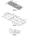
- an alternate bottom wall 50 provides the vibratory diaphragm to which the transducers 24 are coupled.
- the alternate bottom wall 50 is divided into individual domains 52 associated with each location 34, with domains 52A placed at locations 34A and domains 52B placed at locations 34B. As seen in FIG.
- the wall thickness TA of domains 52A is different from, and less than the wall thickness TB of domains 52B, so that the transmission of ultrasonic energy at the higher ultrasonic frequency provided by transducers 24A is optimized by the thinner wall thickness of domains 52A, while the transmission of ultrasonic energy at the lower ultrasonic frequency provided by transducers 24B is permitted through the thicker wall thickness of domains 52B, with the thicker wall thickness compensating for cavitational erosion and enabling a longer service life.
- each domain 52 is constructed of a plate 62 having a generally flat, essentially planar, rectangular configuration with edges 64 extending along the boundaries of the rectangular configuration of each domain 50.
- the preferred material for plates 62 is stainless steel. Plates 62A, which establish domains 52A, are thinner than plates 62B, which establish domains 52B and the plates 62 are joined together at contiguous edges 64, as by welding as shown at 66, to form an integral, essentially flat, bottom wall 50 having thinner domains 52A at locations 34A and thicker domains 52B at locations 34B.
- each plate 62A is about 18 gauge, or 0.0480 inch, while the preferred thickness of each plate 62B is about 12 gauge, or 0.1054 inch.
- the generally rectangular configuration of each plate 62 is a square in which each edge 64 has a length L of about 3.25 inches, thereby providing a distance D between adjacent locations 34A and 348 of about 3.25 inches.
- the transducers 24 are housed in a separate housing 70 which is immersed in the bath 14 within tank 12 and is sealed against the entry of the ultrasonic cleaning fluid of the bath 14.
- the housing includes a top wall 72 which serves as a vibratory diaphragm to which the transducers 24 are coupled for the transmission of ultrasonic energy into the bath 14 to accomplish ultrasonic cleaning of the articles 16 immersed in the bath 14.
- a bottom wall 73 and side walls 74 seal the housing 70.
- the transducers 24 are provided in two sets, with first transducers 24A powered by a first power supply 30 to provide ultrasonic energy at a first ultrasonic frequency, and transducers 24B powered by a second power supply 32 to provide ultrasonic energy at a second ultrasonic frequency different from the first ultrasonic frequency.
- Each power supply 30 and 32 is connected to respective transducers 24 through a conduit 76 extending outside the bath 14 and communicating with the interior 78 of the housing 70.
- an alternate bottom wall 80 for tank 12 includes a domain 82 associated with each location 34 for a transducer 24.
- Bottom wall 80 includes a web 84, with domains 82A placed at locations 34A and domains 84B placed at locations 34B.
- each domain 82 includes a section 86 having a prescribed wall thickness, the wall thickness TA of section 86A of domain 82A being different from, and less than, the wall thickness TB of section 86B of domain 82B.
- Each domain 82 includes a recess 88 associated with the section 86 of the domain 82.
- the domains 82A and 82B are constructed with sections 86A and 86B of different wall thicknesses by merely machining away portions of a sheet of material to establish bottom wall 80 with recesses 88 having different depths to form sections 86A and 86B of different wall thicknesses.
- the recesses 88 are cylindrical and the resulting sections 86 are circular.
- the transducers 24A and 24B then are mounted upon respective sections 86A and 86B, as illustrated in phantom, to optimize the transmission of the higher and lower frequency ultrasonic energy, by virtue of each section 86 providing a vibratory diaphragm best suited to the transducer 24 mounted on the section 86.
- the domains 82 each include an aperture 94 extending through the bottom wall 80, and a plate 96 extending over the aperture 94 and joined to the bottom wall 80 as by welding, as shown at 98.
- the domains 82A and 82B are constructed with plates 96A and 96B of different wall thicknesses, the wall thickness TA of plate 96A of domain 82A being less than the wall thickness TB of plate 96B of domain 82B.
- the apertures 94 are cylindrical and the plates 96 are circular, with a weld 98 following the circular periphery of each plate 96.
- the transducers 24A and 24B then are mounted upon respective plates 96A and 96B, as illustrated in phantom, to optimize the transmission of the higher and lower frequency ultrasonic energy, by virtue of each plate 96 providing a vibratory diaphragm best suited to the transducer 24 mounted on the plate 96.
- the simultaneous transmission of ultrasonic energy of multiple ultrasonic frequencies into a single ultrasonic cleaning bath increases the range of contaminants and particulate size which can be cleaned effectively from a wider variety of articles by ultrasonic cleaning techniques.
- the combination of high-frequency ultrasonic energy and low-frequency ultrasonic energy provided simultaneously in the same bath enables a more evenly distributed cavitational energy, with the higher frequency ultrasonic energy filling the voids between standing waves created by the lower frequency ultrasonic energy, for enhanced cleaning characteristics, both from the standpoint of the range of contaminants and particulate sizes and the increased speed with which total cleaning is accomplished.
- the present invention attains the several objects and advantages summarized above, namely: Enables ultrasonic cleaning of articles through the simultaneous utilization of both low and high frequency ultrasonic energy for more effective ultrasonic cleaning; provides simplified ultrasonic cleaning apparatus in that a single cleaning tank is employed for cleaning with multiple frequency ultrasonic energy utilized simultaneously for efficient ultrasonic cleaning of articles; attains more effective ultrasonic cleaning in less time and with less energy than heretofore accomplished with conventional ultrasonic cleaning apparatus and methods; provides a more uniform ultrasonic energy field throughout an ultrasonic cleaning bath for more efficient cleaning of articles placed in the bath; reduces the time required for completing ultrasonic cleaning operations; increases the reliability and the service life of ultrasonic cleaning apparatus.
Landscapes
- Cleaning By Liquid Or Steam (AREA)
Applications Claiming Priority (2)
| Application Number | Priority Date | Filing Date | Title |
|---|---|---|---|
| US961817 | 1997-10-31 | ||
| US08/961,817 US5865199A (en) | 1997-10-31 | 1997-10-31 | Ultrasonic cleaning apparatus |
Publications (2)
| Publication Number | Publication Date |
|---|---|
| EP0913209A2 true EP0913209A2 (de) | 1999-05-06 |
| EP0913209A3 EP0913209A3 (de) | 2000-07-12 |
Family
ID=25505062
Family Applications (1)
| Application Number | Title | Priority Date | Filing Date |
|---|---|---|---|
| EP98308841A Withdrawn EP0913209A3 (de) | 1997-10-31 | 1998-10-28 | Apparat und Verfahren zur Ultraschallreinigung |
Country Status (2)
| Country | Link |
|---|---|
| US (2) | US5865199A (de) |
| EP (1) | EP0913209A3 (de) |
Cited By (1)
| Publication number | Priority date | Publication date | Assignee | Title |
|---|---|---|---|---|
| US9108232B2 (en) | 2009-10-28 | 2015-08-18 | Megasonic Sweeping, Incorporated | Megasonic multifrequency apparatus with matched transducers and mounting plate |
Families Citing this family (45)
| Publication number | Priority date | Publication date | Assignee | Title |
|---|---|---|---|---|
| US7629726B2 (en) * | 2007-07-11 | 2009-12-08 | Puskas William L | Ultrasound system |
| US6822372B2 (en) * | 1999-08-09 | 2004-11-23 | William L. Puskas | Apparatus, circuitry and methods for cleaning and/or processing with sound waves |
| US6313565B1 (en) | 2000-02-15 | 2001-11-06 | William L. Puskas | Multiple frequency cleaning system |
| FR2755038B1 (fr) * | 1996-10-28 | 1998-12-24 | Forward Technology Ind | Procede de nettoyage de pieces metalliques |
| US6050945A (en) * | 1997-06-27 | 2000-04-18 | Siemens Medical Systems, Inc. | Ultrasound front-end circuit combining the transmitter and automatic transmit/receive switch with agile power level control |
| US6276370B1 (en) * | 1999-06-30 | 2001-08-21 | International Business Machines Corporation | Sonic cleaning with an interference signal |
| DE19939899A1 (de) * | 1999-08-22 | 2001-03-01 | Beissbarth Gmbh | Reinigungseinrichtung für rotationssymmetrische Körper |
| US6494222B1 (en) | 1999-10-28 | 2002-12-17 | Fuji Photo Optical Co., Ltd. | Ultrasonic cleaning apparatus for an endoscope |
| US6481449B1 (en) | 1999-11-03 | 2002-11-19 | Applied Materials, Inc. | Ultrasonic metal finishing |
| US6619305B1 (en) | 2000-01-11 | 2003-09-16 | Seagate Technology Llc | Apparatus for single disc ultrasonic cleaning |
| US7451774B2 (en) * | 2000-06-26 | 2008-11-18 | Applied Materials, Inc. | Method and apparatus for wafer cleaning |
| AU2001270205A1 (en) * | 2000-06-26 | 2002-01-08 | Applied Materials, Inc. | Method and apparatus for wafer cleaning |
| JP3768789B2 (ja) * | 2000-09-07 | 2006-04-19 | アルプス電気株式会社 | 超音波振動子及びウエット処理用ノズル並びにウエット処理装置 |
| US20020157685A1 (en) * | 2000-09-11 | 2002-10-31 | Naoya Hayamizu | Washing method, method of manufacturing semiconductor device and method of manufacturing active matrix-type display device |
| US6736904B2 (en) | 2001-03-02 | 2004-05-18 | Paper Quality Management Associates | Method and apparatus for the generation of ultrasonic energy fields within circular structures containing a liquid |
| US6595224B2 (en) * | 2001-06-20 | 2003-07-22 | P.C.T. Systems, Inc. | Bath system with sonic transducers on vertical and angled walls |
| JP3948960B2 (ja) * | 2002-01-16 | 2007-07-25 | 東京エレクトロン株式会社 | 超音波洗浄装置 |
| JP3092396U (ja) * | 2002-08-28 | 2003-03-07 | エレコン科学株式会社 | 交差超音波破砕器 |
| US7104268B2 (en) * | 2003-01-10 | 2006-09-12 | Akrion Technologies, Inc. | Megasonic cleaning system with buffered cavitation method |
| JP2007523738A (ja) * | 2003-11-05 | 2007-08-23 | ザ・クレスト・グループ・インク | 複数の応答周波数を持つトランスデューサを用いた超音波処理方法および超音波処理装置 |
| US20060130870A1 (en) * | 2004-12-21 | 2006-06-22 | Ping Cai | Method for sonic cleaning of reactor with reduced acoustic wave cancellation |
| WO2006138438A2 (en) * | 2005-06-15 | 2006-12-28 | Akrion, Inc. | System and method of processing substrates using sonic energy having cavitation control |
| TWI393595B (zh) * | 2006-03-17 | 2013-04-21 | 麥克 固得桑 J | 具有頻率掃描的厚度模式轉換器之超高頻音波處理設備 |
| DE202007003176U1 (de) * | 2007-03-01 | 2007-10-18 | Ima Kilian Gmbh & Co.Kg | Rotationstablettenpresse mit Wascheinrichtung |
| RU2357810C2 (ru) * | 2007-05-17 | 2009-06-10 | ОАО "Особое конструкторско-технологическое бюро Кристалл" | Способ очистки с использованием ультразвуковой энергии различной частоты |
| RU2378058C1 (ru) * | 2008-07-01 | 2010-01-10 | Государственное образовательное учреждение высшего профессионального образования Московский автомобильно-дорожный институт (Государственный технический университет) | Способ ультразвуковой очистки изделий |
| JP5329352B2 (ja) * | 2009-09-08 | 2013-10-30 | 東京エレクトロン株式会社 | 超音波洗浄装置、超音波洗浄方法、およびこの超音波洗浄方法を実行するためのコンピュータプログラムが記録された記録媒体 |
| WO2011075831A2 (en) * | 2009-12-22 | 2011-06-30 | William Lash Phillips | Apparatus for cleaning industrial components |
| KR20120080882A (ko) * | 2011-01-10 | 2012-07-18 | 삼성전자주식회사 | 음향 변환기 및 그 구동방법 |
| US9266117B2 (en) | 2011-09-20 | 2016-02-23 | Jo-Ann Reif | Process and system for treating particulate solids |
| CN102489470A (zh) * | 2011-12-07 | 2012-06-13 | 深圳市华星光电技术有限公司 | 玻璃基板的清洗装置及清洗方法 |
| US20130146085A1 (en) * | 2011-12-07 | 2013-06-13 | Shenzhen China Star Optoelectronics Technology Co., Ltd. | Glass substrate cleaning apparatus and cleaning method |
| US8945311B2 (en) * | 2012-03-19 | 2015-02-03 | Shenzhen China Star Optoelectronics Technology Co., Ltd. | Method for cleansing glass substrate of TFT-LCD |
| CN102601074B (zh) * | 2012-03-19 | 2015-08-12 | 深圳市华星光电技术有限公司 | Tft-lcd玻璃基板清洗方法 |
| US9192968B2 (en) | 2012-09-20 | 2015-11-24 | Wave Particle Processing | Process and system for treating particulate solids |
| CN103506348A (zh) * | 2013-03-26 | 2014-01-15 | 新能(张家港)能源有限公司 | 一种二甲醚取样器清洗装置 |
| WO2014193315A1 (en) * | 2013-05-30 | 2014-12-04 | Agricultural Research Development Agency (Public Organization) | Ultrasonic cleaning and disinfecting device and method |
| CN105149288A (zh) * | 2015-10-19 | 2015-12-16 | 无锡清杨机械制造有限公司 | 一种利用变频超声清洁物件的方法 |
| WO2017070095A1 (en) * | 2015-10-19 | 2017-04-27 | The Trustees Of The University Of Pennsylvania | Apparatus and methods for improving catheter function |
| CN105396834A (zh) * | 2015-11-20 | 2016-03-16 | 无锡南方声学工程有限公司 | 一种超声波清洗机振盒结构 |
| CN106140724A (zh) * | 2016-09-30 | 2016-11-23 | 四川行来科技有限公司 | 一种超声波薄膜清洗机 |
| US10792781B2 (en) | 2018-04-13 | 2020-10-06 | Bell Helicopter Textron Inc. | Masking tool system and method |
| KR102871802B1 (ko) * | 2019-12-19 | 2025-10-16 | 닛테츠 엔지니어링 가부시키가이샤 | 초음파 처리 장치 |
| US11945014B2 (en) | 2020-01-24 | 2024-04-02 | New Jersey Institute Of Technology | Coupled high and low-frequency ultrasound systems and methods for remediation of contaminated solids |
| US12528721B2 (en) | 2020-09-04 | 2026-01-20 | New Jersey Institute Of Technology | Ultrasound device for destruction of organic chemicals |
Family Cites Families (11)
| Publication number | Priority date | Publication date | Assignee | Title |
|---|---|---|---|---|
| GB1488252A (en) * | 1973-12-15 | 1977-10-12 | Kerry Ultrasonics | Ultrasonic cleaning apparatus |
| US4118649A (en) * | 1977-05-25 | 1978-10-03 | Rca Corporation | Transducer assembly for megasonic cleaning |
| JPS59123226A (ja) * | 1982-12-28 | 1984-07-17 | Fujitsu Ltd | 半導体装置の製造装置 |
| US4527901A (en) * | 1983-11-21 | 1985-07-09 | Ultrasonic Power Corporation | Ultrasonic cleaning tank |
| EP0225113A3 (de) * | 1985-11-19 | 1988-12-14 | Westinghouse Electric Corporation | Magnetostriktives Wandlergerät |
| US5119840A (en) * | 1986-04-07 | 1992-06-09 | Kaijo Kenki Co., Ltd. | Ultrasonic oscillating device and ultrasonic washing apparatus using the same |
| JPH0234923A (ja) * | 1988-07-25 | 1990-02-05 | Toshiba Corp | 超音波洗浄装置 |
| US5038808A (en) * | 1990-03-15 | 1991-08-13 | S&K Products International, Inc. | High frequency ultrasonic system |
| US5247954A (en) * | 1991-11-12 | 1993-09-28 | Submicron Systems, Inc. | Megasonic cleaning system |
| JP3336323B2 (ja) * | 1993-10-28 | 2002-10-21 | 本多電子株式会社 | 超音波洗浄方法及びその装置 |
| JPH08141527A (ja) * | 1994-11-21 | 1996-06-04 | Otsuka Giken Kogyo Kk | 超音波洗浄装置 |
-
1997
- 1997-10-31 US US08/961,817 patent/US5865199A/en not_active Expired - Lifetime
-
1998
- 1998-10-28 EP EP98308841A patent/EP0913209A3/de not_active Withdrawn
- 1998-12-16 US US09/213,014 patent/US6019852A/en not_active Expired - Lifetime
Cited By (2)
| Publication number | Priority date | Publication date | Assignee | Title |
|---|---|---|---|---|
| US9108232B2 (en) | 2009-10-28 | 2015-08-18 | Megasonic Sweeping, Incorporated | Megasonic multifrequency apparatus with matched transducers and mounting plate |
| US9610617B2 (en) | 2009-10-28 | 2017-04-04 | Megasonic Sweeping, Incorporated | Megasonic multifrequency apparatus with matched transducer |
Also Published As
| Publication number | Publication date |
|---|---|
| EP0913209A3 (de) | 2000-07-12 |
| US6019852A (en) | 2000-02-01 |
| US5865199A (en) | 1999-02-02 |
Similar Documents
| Publication | Publication Date | Title |
|---|---|---|
| US5865199A (en) | Ultrasonic cleaning apparatus | |
| US3329408A (en) | Transducer mounting arrangement | |
| US9610617B2 (en) | Megasonic multifrequency apparatus with matched transducer | |
| US3058014A (en) | Apparatus for generating sonic vibrations in liquids | |
| EP2382619B1 (de) | Integrierte schaltung mit störakustikmodusunterdrückung und herstellungsverfahren dafür | |
| US4943954A (en) | Method and a system for counteracting marine biologic fouling of a hull or a submerged construction | |
| WO2005006936A1 (en) | Three-dimentional ultrasonic generating washing device | |
| KR0170996B1 (ko) | 초음파 방식 식기 세척기 | |
| CN1246091C (zh) | 超声清洗多个相邻分布条状产品如导线、型钢和管的装置 | |
| AU642418B2 (en) | A method and a system for combating marine fouling | |
| JP3839154B2 (ja) | 超音波振動発生装置及び超音波洗浄装置 | |
| JP2005053203A (ja) | 切断装置 | |
| JP3854406B2 (ja) | 超音波洗浄装置 | |
| JP3918966B2 (ja) | キャビテーション検出方法 | |
| JPH03159801A (ja) | ランジュバン型超音波振動子の振動振幅平坦化方法 | |
| JPH0513433Y2 (de) | ||
| SU1622025A1 (ru) | Ультразвуковой пьезокерамический преобразователь дл озвучивани жидкости | |
| JP2003326226A (ja) | 超音波振動子及びそれを用いた超音波洗浄器 | |
| US20240034647A1 (en) | Device for separating legionella | |
| JPH07313939A (ja) | 超音波洗浄機 | |
| JP2012125743A (ja) | 超音波振動子ユニット | |
| JP2004154771A (ja) | 超音波洗浄装置 | |
| JPH05146756A (ja) | 超音波振動板 | |
| KR910008409B1 (ko) | 초음파 세척기의 압전랸쥬반형 트랜스 듀서 제조방법 | |
| JPS59124489A (ja) | 船体外板の防汚方法 |
Legal Events
| Date | Code | Title | Description |
|---|---|---|---|
| PUAI | Public reference made under article 153(3) epc to a published international application that has entered the european phase |
Free format text: ORIGINAL CODE: 0009012 |
|
| AK | Designated contracting states |
Kind code of ref document: A2 Designated state(s): DE FR GB |
|
| AX | Request for extension of the european patent |
Free format text: AL;LT;LV;MK;RO;SI |
|
| 17P | Request for examination filed |
Effective date: 19991102 |
|
| PUAL | Search report despatched |
Free format text: ORIGINAL CODE: 0009013 |
|
| AK | Designated contracting states |
Kind code of ref document: A3 Designated state(s): AT BE CH CY DE DK ES FI FR GB GR IE IT LI LU MC NL PT SE |
|
| AX | Request for extension of the european patent |
Free format text: AL;LT;LV;MK;RO;SI |
|
| AKX | Designation fees paid |
Free format text: DE FR GB |
|
| STAA | Information on the status of an ep patent application or granted ep patent |
Free format text: STATUS: THE APPLICATION IS DEEMED TO BE WITHDRAWN |
|
| 18D | Application deemed to be withdrawn |
Effective date: 20010501 |