EP0913264A2 - Station de maintenance pour tête d'impression à jet d'encre - Google Patents
Station de maintenance pour tête d'impression à jet d'encre Download PDFInfo
- Publication number
- EP0913264A2 EP0913264A2 EP98308809A EP98308809A EP0913264A2 EP 0913264 A2 EP0913264 A2 EP 0913264A2 EP 98308809 A EP98308809 A EP 98308809A EP 98308809 A EP98308809 A EP 98308809A EP 0913264 A2 EP0913264 A2 EP 0913264A2
- Authority
- EP
- European Patent Office
- Prior art keywords
- wiper
- cam
- servicing
- printhead
- cap
- Prior art date
- Legal status (The legal status is an assumption and is not a legal conclusion. Google has not performed a legal analysis and makes no representation as to the accuracy of the status listed.)
- Withdrawn
Links
- 230000007246 mechanism Effects 0.000 claims abstract description 38
- 238000007641 inkjet printing Methods 0.000 claims abstract description 31
- 238000007639 printing Methods 0.000 claims abstract description 31
- 238000000034 method Methods 0.000 claims abstract description 16
- 238000007789 sealing Methods 0.000 claims description 13
- 238000004140 cleaning Methods 0.000 claims description 5
- 238000003384 imaging method Methods 0.000 abstract description 35
- 239000003086 colorant Substances 0.000 abstract description 24
- 238000009472 formulation Methods 0.000 abstract description 4
- 239000000203 mixture Substances 0.000 abstract description 4
- 239000000976 ink Substances 0.000 description 69
- 230000000712 assembly Effects 0.000 description 14
- 238000000429 assembly Methods 0.000 description 14
- 230000009977 dual effect Effects 0.000 description 14
- 239000000835 fiber Substances 0.000 description 8
- 239000001042 pigment based ink Substances 0.000 description 8
- 239000001041 dye based ink Substances 0.000 description 7
- 238000010304 firing Methods 0.000 description 6
- 230000004044 response Effects 0.000 description 6
- 238000010276 construction Methods 0.000 description 5
- 239000002131 composite material Substances 0.000 description 4
- 239000000049 pigment Substances 0.000 description 4
- 244000309464 bull Species 0.000 description 3
- 238000001035 drying Methods 0.000 description 3
- 210000003128 head Anatomy 0.000 description 3
- 239000000463 material Substances 0.000 description 3
- NJPPVKZQTLUDBO-UHFFFAOYSA-N novaluron Chemical compound C1=C(Cl)C(OC(F)(F)C(OC(F)(F)F)F)=CC=C1NC(=O)NC(=O)C1=C(F)C=CC=C1F NJPPVKZQTLUDBO-UHFFFAOYSA-N 0.000 description 3
- 239000000758 substrate Substances 0.000 description 3
- 230000000007 visual effect Effects 0.000 description 3
- 230000008901 benefit Effects 0.000 description 2
- 230000007423 decrease Effects 0.000 description 2
- 239000000428 dust Substances 0.000 description 2
- 239000007788 liquid Substances 0.000 description 2
- 230000008569 process Effects 0.000 description 2
- 210000004894 snout Anatomy 0.000 description 2
- 238000003860 storage Methods 0.000 description 2
- 230000007704 transition Effects 0.000 description 2
- 238000009834 vaporization Methods 0.000 description 2
- 230000008016 vaporization Effects 0.000 description 2
- 229920002799 BoPET Polymers 0.000 description 1
- 208000001613 Gambling Diseases 0.000 description 1
- 239000005041 Mylar™ Substances 0.000 description 1
- 208000003028 Stuttering Diseases 0.000 description 1
- 230000009471 action Effects 0.000 description 1
- 230000003213 activating effect Effects 0.000 description 1
- 230000004913 activation Effects 0.000 description 1
- 239000000853 adhesive Substances 0.000 description 1
- 230000001070 adhesive effect Effects 0.000 description 1
- 238000003491 array Methods 0.000 description 1
- 230000004888 barrier function Effects 0.000 description 1
- 238000004891 communication Methods 0.000 description 1
- 239000004020 conductor Substances 0.000 description 1
- 239000000356 contaminant Substances 0.000 description 1
- 238000011109 contamination Methods 0.000 description 1
- 238000000151 deposition Methods 0.000 description 1
- 230000000994 depressogenic effect Effects 0.000 description 1
- 230000003028 elevating effect Effects 0.000 description 1
- 238000005516 engineering process Methods 0.000 description 1
- 239000004744 fabric Substances 0.000 description 1
- 239000011888 foil Substances 0.000 description 1
- 230000036541 health Effects 0.000 description 1
- 238000010438 heat treatment Methods 0.000 description 1
- 238000007689 inspection Methods 0.000 description 1
- 238000009434 installation Methods 0.000 description 1
- 238000004519 manufacturing process Methods 0.000 description 1
- 238000002156 mixing Methods 0.000 description 1
- 238000000465 moulding Methods 0.000 description 1
- 230000003287 optical effect Effects 0.000 description 1
- 239000012188 paraffin wax Substances 0.000 description 1
- 238000005192 partition Methods 0.000 description 1
- 239000004033 plastic Substances 0.000 description 1
- 238000003825 pressing Methods 0.000 description 1
- 230000037452 priming Effects 0.000 description 1
- 238000005086 pumping Methods 0.000 description 1
- 238000009877 rendering Methods 0.000 description 1
- 230000000284 resting effect Effects 0.000 description 1
- 238000005201 scrubbing Methods 0.000 description 1
- 239000002904 solvent Substances 0.000 description 1
- 238000005092 sublimation method Methods 0.000 description 1
- 239000002699 waste material Substances 0.000 description 1
Images




Classifications
-
- B—PERFORMING OPERATIONS; TRANSPORTING
- B41—PRINTING; LINING MACHINES; TYPEWRITERS; STAMPS
- B41J—TYPEWRITERS; SELECTIVE PRINTING MECHANISMS, i.e. MECHANISMS PRINTING OTHERWISE THAN FROM A FORME; CORRECTION OF TYPOGRAPHICAL ERRORS
- B41J2/00—Typewriters or selective printing mechanisms characterised by the printing or marking process for which they are designed
- B41J2/005—Typewriters or selective printing mechanisms characterised by the printing or marking process for which they are designed characterised by bringing liquid or particles selectively into contact with a printing material
- B41J2/01—Ink jet
- B41J2/135—Nozzles
- B41J2/165—Prevention or detection of nozzle clogging, e.g. cleaning, capping or moistening for nozzles
- B41J2/16517—Cleaning of print head nozzles
- B41J2/16535—Cleaning of print head nozzles using wiping constructions
- B41J2/16544—Constructions for the positioning of wipers
- B41J2/16547—Constructions for the positioning of wipers the wipers and caps or spittoons being on the same movable support
Definitions
- the present invention relates generally to inkjet printing mechanisms, and more particularly to a timing cam driven service station for a triple-cartridge inkjet printing mechanism that receives a first inkjet cartridge and interchangeably receives one of at least two different types of inkjet cartridges, such as a black ink cartridge or a multi-color ink cartridge, each of which has different servicing needs.
- Inkjet printing mechanisms use cartridges or "pens” which shoot drops of liquid colorant, referred to generally herein as "ink", onto a page.
- Each pen has a printhead formed with very small nozzles or slits through which the ink drops are fired. To print an image, the printhead is propelled back and forth across the page, shooting drops of ink in a desired pattern as it moves.
- the particular ink ejection mechanism within the printhead may take on a variety of different forms known to those skilled in the art, such as those using piezo-electric or thennal printhead technology. For instance, two earlier thermal ink ejection mechanisms are shown in U.S. Patent Nos.
- a barrier layer containing ink channels and vaporization chambers is located between a nozzle orifice plate and a substrate layer.
- This substrate layer typically contains linear arrays of heater elements, such as resistors, which are energized to heat ink within the vaporization chambers.
- resistors such as resistors
- an ink droplet is ejected from a nozzle associated with the energized resistor.
- a “service station” mechanism is mounted within the printer chassis.
- service stations usually include a capping system which seals the printhead nozzles from contaminants and drying.
- Some caps are also designed to facilitate priming, such as by being connected to a pumping unit that draws a vacuum on the printhead.
- clogs in the printhead are periodically cleared by firing a number of drops of ink through each of the nozzles in a process known as "spitting.”
- the waste ink is collected in a stationary reservoir portion of the service station, which is often referred to as a “spittoon.”
- a spintoon After spitting, uncapping, or occasionally during printing, most service stations have an elastomeric wiper that wipes the printhead surface to remove ink residue, as well as any paper dust or other debris that has collected on the printhead.
- printers further enhanced the images by using a dual pen system.
- These dual pen printers provided a black pen along with a tri-color pen, both of which were mounted in a single carriage.
- These dual pen devices had the ability to print crisp, clear black text while providing full color images.
- One earlier dual pen inkjet printing mechanism was sold by the Hewlett-Packard Company of Palo Alto, California, the present assignee, as the DeskJet® 320 portable inkjet printer.
- a quad pen printing mechanism was developed which carried four cartridges in a single carriage. These quad pen printing mechanisms had a first pen carrying black ink, a second pen carrying cyan ink, a third pen carrying magenta ink, and a fourth pen carrying yellow ink.
- both the quad pen printers and the dual pen printers produced images, such as photographic images, which had a "grainy" appearance.
- images such as photographic images
- a light colored portion of an image such as a flesh tone
- yellow dots were printed and lightly interspersed with magenta dots.
- magenta dots When viewed at a distance, these magenta dots provided a flesh tone appearance; however, upon closer inspection the magenta dots were quite visible, giving the image an undesirable grainy appearance.
- This grainy appearance was similar to the graininess seen in newspaper photographs, or in photos taken using the wrong speed (“ASA” or "ISO” rating) of photographic film in low light conditions.
- Inkjet printing mechanisms are known as “binary drop devices” because they form images either by firing to place a drop of ink on the print medium, or by not firing.
- imaging Another printing system, known as an "imaging” printing system, has been proposed.
- a basic dual pen printer platform typically constructed for a monochrome (e.g. black) cartridge and a tri-color (e.g. cyan, magenta, yellow) cartridge
- the monochrome cartridge is replaced with a tri-chamber "imaging cartridge.”
- the imaging cartridge typically carries ink formulations having reduced colorant concentrations.
- the imaging cartridge may contain reduced colorant concentrations of cyan and magenta, and a full concentration of black ink.
- a scrubbing type of wiping routine is preferred to clean the tar-like pigment ink residue from the printheads. If a faster wipe was used to accommodate the dye based inks, the wiper for the pigment based ink is prevented from making full contact with the residue. Instead, the wiper skips over bumps formed from the tar-like pigment based ink residue in a jerking or stuttering type of motion, which failed to remove the residue from the printhead. In some cases, during this faster wiping stroke the wiper for the pigment based ink flexed and skimmed over the tar-like residue, which smeared the ink over the orifice plate rather than removing it. Thus, any compromise in attempting to accommodate the wiping needs of one pen was at the sacrifice of meeting the needs of the other type of pen.
- a service station for servicing an inkjet printhead of an inkjet printing mechanism.
- the service station includes a frame and a cap cam follower slideably mounted to the frame for translational motion toward the printhead into a capping position.
- a cap is supported by the cap cam follower to seal the printhead in the capping position.
- a wiper cam follower is slideably mounted to the frame for translational motion toward the printhead into a wiping position, with a wiper being supported by the wiper cam follower to clean the printhead in the wiping position.
- the service station also has a timing cam drive which includes a drive shaft with a cap cam, and a wiper cam mounted on the drive shaft. The cap cam engages the cap cam follower for movement between the capping position and a rest position, while the wiper cam engages the wiper cam follower for movement between the wiping position and a rest position.
- the service station is also for servicing a second inkjet printhead of the inkjet printing mechanism, with the service station further comprising:
- said wiper cam and the second wiper cam are configured and driven by the drive shaft for selectively:
- the printhead is reciprocated by a carriage of the inkjet printing mechanism
- the service station further comprising: a carriage lock cam follower slideably mounted to the frame for transitional motion toward the carriage into a locking position; a carriage lock supported by the carriage lock cam follower to latch the carriage in a fixed position when the carriage lock cam follower is in the locking position; and wherein the timing cam drive has a carriage lock cam supported by the drive shaft to latch the carriage when the cap cam follower is in the capping position, with the carriage lock cam engaging the carriage lock cam follower for movement between the locking position and a rest position.
- the service station may further comprise a carriage lock biasing member that urges carriage lock and carriage lock cam follower away form the locking position.
- the service station comprises: a cap base that joins the cap to the cap cam follower for gamballing motion of the cap with respect to the cap cam follower; a cap biasing member that urges the cap toward the printhead; a wiper base that joins the wiper to the wiper cam follower for gambling motion of the wiper with respect to the wiper cam follower; and a wiper biasing member that urges the wiper toward the printhead; preferably, a cap biasing member is sandwiched between the cap base and the cap cam follower; and a wiper biasing member is sandwiched between the wiper base and the wiper cam follower.
- a service station for servicing a pair of inkjet printheads of an inkjet printing mechanism.
- the service station has first, second, third and fourth cam followers each slideably mounted to a frame for transitional motion into servicing positions for the inkjet printheads.
- the service station also has a pair of wipers and a pair of caps.
- the service station also has a timing cam drive having a drive shaft with first, second, third and fourth cams mounted on the shaft to engage the respective first, second, third and fourth cam followers for selectively moving the pair of wipers and the pair of caps into their servicing positions.
- the third and fourth cams are configured to simultaneously move the pair of caps into the capping position to seal the pair of printheads.
- the pair of inkjet printheads are reciprocated by a carriage of the inkjet printing mechanism, with the service station further comprising:
- first and second cams are configured to:
- an inkjet printing mechanism which may have a service station as described above.
- a method of servicing an inkjet printhead of an inkjet printing mechanism includes the step of providing a cap supported by a cap cam follower, a wiper supported by a wiper cam follower, and a timing cam drive having a drive shaft with a cap cam and a wiper cam mounted thereon.
- a sealing step the inkjet printhead is sealed by translationally moving the cap into a capping position by engaging the cap cam with the cap cam follower.
- the inkjet printhead is cleaned by translationally moving the wiper into a wiper position by engaging the wiper cam with the wiper cam follower, and thereafter, by moving the inkjet printhead across the wiper.
- the providing step comprises providing a carriage lock supported by a carriage lock cam follower, and providing a carriage lock cam mounted on the drive shaft;
- a method of servicing a pair of inkjet printheads of an inkjet printing mechanism includes the step of providing first, second and third and fourth cam followers supporting respective first, second, third and fourth servicing components, and providing a timing cam drive having a drive shaft with first, second, third and fourth cams mounted thereon.
- a moving step at least one of hte first, second, third and fourth servicing components is selectively moved into a servicing position through rotation of the drive shaft and engagement of the first, second, third and fourth cam followers with respective first, second, third and fourth cams.
- the inkjet printheads are serviced with at least one of the first, second, third and fourth servicing components when in the servicing position.
- the providing step comprises providing said first and second servicing components as a pair of wipers;
- the providing step comprises providing said first and second servicing components as a pair of wipers;
- the providing step comprises providing said third and fourth servicing components as a pair of caps;
- An overall goal of the present invention is to maintain cartridge health and provide a inkjet printing mechanism which prints sharp vivid images when using either a monochrome inkjet cartridge or a multi-color imaging inkjet cartridge in combination with full color cartridge.
- Another goal of the present invention is to provide a robust wiping system capable of reliably cleaning the nozzle face plates of inkjet printheads having different wiping needs, such as one dispensing a fast drying pigment based ink and one dispensing a fast drying dye based ink, without sacrificing printing speed or throughput rating.
- FIG. 1 is a partially cut away, perspective view of one form of an inkjet printing mechanism, here an inkjet printer, incorporating one form of a timing cam driven inkjet printhead service station of the present invention.
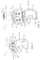
- FIG. 2 is an exploded perspective view of the service station of FIG. 1, showing a drive motor, transfer gear, and microswitch removed.
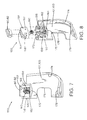
- FIG. 3 is an enlarged, cut away perspective view of the service station of FIG. 1.
- FIG. 4 is an exploded perspective view of several servicing components, cam followers, and a timing cam drive of the service station of FIG. 1.
- FIG. 5 is a side elevational view of one of the capping assemblies of the service station of FIG. 1.
- FIG. 6 is an exploded perspective view of the capping components and cam follower support of FIG. 5.
- FIG. 7 is a side elevational view of one of the wiping assemblied of the service station of FIG. 1.
- FIG. 8 is an exploded perspective view of the wiping components and cam follower support of FIG. 7.
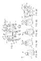
- FIG. 9 is a front elevational view of the capping position of the timing cam drive, with both capping assemblies and both wiping assemblies of the service station of FIG. 1 assembled thereon, used as a reference for several side elevational views thereof, specifically :
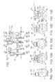
- FIG. 10 is a front elevational view of the combination wiper wiping position of the timing cam drive, with both capping assemblies and both wiping assemblies of the service station of FIG. 1 assembled thereon, used as a reference for several side elevational views thereof, specifically:
- FIG. 11 is a front elevational view of the simultaneous wiping position of the timing cam drive, with both capping assemblies and both wiping assemblies of the service station of FIG. 1 assembled thereon, used as a reference for several side elevational views thereof, specifically:
- FIG. 12 is a front elevational view of the full color wiper wiping position of the timing cam drive, with both capping assemblies and both wiping assemblies of the service station of FIG. 1 assembled thereon, used as a reference for several side elevational views thereof, specifically:
- FIG. 1 illustrates an embodiment of an inkjet printing mechanism, here shown as an inkjet printer 20, constructed in accordance with the present invention, which may be used for printing for business reports, correspondence, desktop publishing and the like, in an industrial, office, home or other environment.
- inkjet printing mechanisms are commercially available.
- some of the printing mechanisms that may embody the present invention include plotters, portable printing units, copiers, cameras, video printers, and facsimile machines, to name a few.
- the concepts of the present invention are illustrated in the environment of an inkjet printer 20.
- the typical inkjet printer 20 includes a chassis 22 which may be surrounded by a casing, housing or enclosure 23, preferably of a plastic material.
- the printer 20 also includes a print medium handling system 24 for supplying sheets of print media to the printer 20.
- the media handling system 24 moves a sheet or page of print media through a printzone 25 from an input feed tray 26, inside the housing 23 for printing, then to an output tray 28.
- the print media may be any type of suitable sheet material, such as paper, card-stock, transparencies, mylar, foils, fabric, and the like, but for convenience, the illustrated embodiment is described using paper as the print medium.
- the media handling system 24 may include a series of adjustment mechanims for accommodating different sizes of print media, including letter, legal, A-4, envelopes, etc., such as a sliding length adjustment portion 30 of the output tray 28, and a sliding width adjustment lever 32.
- the output tray 28, 40 pivots around axis 34 to fold up against the exterior of the casing 23 for storage.
- the printer 20 also has a printer controller, illustrated schematically as a microprocessor 35, that receives instructions from a host device, typically a computer, such as a personal computer (not shown).
- the printer controller 35 may also operate in response to user inputs provided through a key pad 16 located on the exterior of the casing 23.
- a monitor coupled to the computer host may be used to display visual information to an operator, such as the printer status or a particular program being run on the host computer.
- personal computers, their input devices, such as a keyboard and/or a mouse device, and monitors are all well known to those skilled in the an.
- a carriage guide rod 38 is mounted to the printer chassis 22 to slideably support a dual inkjet pen carriage 40 for travel back and forth across the printzone 25 along a scanning axis 42 that extends over the printzone 25 and a servicing region 44.
- a conventional carriage drive gear and DC motor assembly (not shown) may be coupled to drive an endless belt (not shown), secured to the carriage 40 in a conventional manner, to incrementally advance the carriage along guide rod 38 in response to rotation of the motor.
- the motor may operate in response to control signals received from the controller 35 to position the carriage 40 at selected locations over the printzone 25 and into the servicing region 44.
- an encoder strip (not shown) may extend along the length of the printzone 25 and over the servicing region 44, with a conventional optical encoder reader (not shown) mounted on the back surface of printhead carriage 40 to read positional information provided by the encoder strip.
- the manner of attaching the endless belt to the carriage 40, as well as the manner providing positional feedback information via the encoder strip reader, may be accomplished in a variety of different ways known to those skilled in the art.
- the media sheet receives ink from an inkjet cartridge, such as a single-chamber style monochrome, black ink cartridge 50, and/or a multi-chamber style, full color ink cartridge 52.
- an imaging printing system has been proposed where the single-chamber black pen 50 is replaced with a multi-chamber imaging cartridge 53, as shown in FIG. 2.
- the imaging cartridge 53 illustrated herein has the same general construction as the full color pen 52, but instead may carry reduced colorant concentrations of ink, as described further below.
- These inkjet cartridges 50, 52 and 53 are also often called "pens" by those in the art.
- pen 50 is referred to herein as either the “monochrome pen” or the “black pen”
- pen 52 is called the “full color pen” referring to the full dye loads contained therein
- pen 53 is called the “imaging pen” because it may be used in conjunction with the full color pen 52 to print superior, near photographic quality images, such as portraits, landscapes, and the like.
- the illustrated pens 50, 52 and 53 each include reservoirs or chambers for storing a supply of ink, and printheads 54, 55 and 56 respectively, for selectively ejecting the ink.
- the illustrated full color pen 52 is a multi-chamber pen having three reservoirs or chambers containing three dye-based ink colors, such as full colorant concentrations of cyan, yellow and magenta inks.
- the black ink pen 50 is illustrated herein as a single-chamber cartridge containing a dye-based ink. It is apparent that other types of inks may also be used in the illustrated cartridges, such as pigment-based inks, paraffin-based inks, as well as hybrid or composite inks having both dye and pigment characteristics.
- the black and color pens may be of different sizes, in the illustrated embodiment, the pens 50, 52 are of substantially the same size.
- the carriage 40 may be modified to interchangeably accommodate narrow and wider pens, for instance, by using the concepts disclosed in U.S. Patent No. 5,208,610, assigned to the present assignee Hewlett-Packard Company.
- Each printhead 54-56 has an orifice plate with a plurality of nozzles formed therethrough in a manner well known to those skilled in the art.
- the illustrated printheads 54-56 are thermal inkjet printheads, although other types of printheads may be used, such as piezoelectric printheads.
- the printheads 54-56 typically include a substrate layer having a plurality of resistors which are associated with the nozzles. Upon energizing a selected resistor, a bubble of gas is formed to eject a droplet of ink from the nozzle and onto the page in the printzone 25 to form a selected image.
- the printhead resistors are selectively energized in response to firing command control signals which may be delivered by a conventional multi-conductor strip (not shown) from the printer controller 35 to the printhead carriage 40.
- a reduced colorant concentration may be composed by maintaining the same amount of solvent or carrier for a given pen capacity while reducing the amount of dye in the concentration from that conventionally used for a full concentration.
- Reduced colorant concentrations of cyan and magenta are often preferred, rather than yellow because visually, yellows is a low contrast color, and any graininess of the yellow ink is not visually detectable to the human eye.
- the third chamber may contain an ink formulation of either a reduced or full concentration of yellow colored ink, or a full or reduced concentration of black ink.
- a reduced yellow concentration may enhance transition regions in areas of flesh tones.
- Table 1 lists a variety of different interchangeable pen and ink formulation combinations, which may be implemented to provide a dual (or multiple) personality printer, capable of producing a variety of different types of output, each with outstanding print quality.
- the pens may each have a unique identifier for automatic recognition by the controller 35, such as a distinct binary code and/or resistors of different resistances. These identifiers are decodeable by the software or firmware of the printer controller 35, and/or the software of a printer driver, located in a host computer or device which communicates with printer 20.
- a unique identifier for automatic recognition by the controller 35 such as a distinct binary code and/or resistors of different resistances. These identifiers are decodeable by the software or firmware of the printer controller 35, and/or the software of a printer driver, located in a host computer or device which communicates with printer 20.
- One suitable identification scheme for interchangeable printheads is disclosed in U.S. Patent No. 4,872,027, also assigned to the present assignee, Hewlett-Packard Company.
- an operator may indicate which cartridge is installed, by making an appropriate entry into a host computer or by merely pressing a button on the keypad 46.
- the software driver within the host computer or printer then uses an appropriate rendering scheme suitable to which ever pen is installed.
- the printer controller 35 then employs suitable print modes and control parameters to generate firing signals to properly fire the installed cartridges 52, and either 50 or 53.
- FIGS. 2-12E show one embodiment of a timing cam driven printhead service station 60, constructed in accordance with the present invention, for servicing the single-chamber monochrome inkjet cartridge 50, and the multi-chamber color inkjet cartridges, specifically the full color cartridge 52 and the imaging cartridge 53.
- the service station 60 includes a frame 62 which is supported by the printer chassis 22 in the servicing region 44.
- the frame 62 is configured to define a spittoon portion 64 of the service station 60, into which ink is ejected or "spit" to clear any clogs or blockages from the nozzles of printheads 54-56.
- the spittoon 64 may be constructed in a conventional manner, including a liner (not shown) of an absorvent material to absorb liquid ink residue.
- the service station 60 includes a motor 65, such as a conventional stepper motor, housed within the frame 62.
- the motor 65 has a pinion gear 66, mounted to an output shaft of the motor, and extending through a slot 67 defined by an outboard side wall 68 of the service station frame 62.
- the motor 65 may be secured to the frame side wall 68 by a pair of screws as shown, or by other fasteners or attachment schemes known to those skilled in the art.
- the motor 65 may operate bi-directionally in response to control signals receipted from the printer controller 35 to drive an intermediate transfer or idler gear 70, and in particular, a bull gear portion 72 of gear 70.
- the idler gear 70 may be mounted to the service station frame wall 68 in a variety of different ways, such as by press-fitting a flanged shaft 74 into a mounting hole 75 defined by the frame side wall 68.
- the idler gear 70 has an output pinion portion 76 which drives a bull gear 78, described in further detail below.
- FIG. 3 shows the service station 60 as including a combination wiper 80 for wiping either (1) the black printhead 54 when the black cartridge 50 is installed in carriage 40, or (2) the imaging printhead 56 when the imaging cartridge 53 is installed in carriage 40.
- the service station 60 also has a color wiper 82 for wiping the color printhead 55 of the full color inkjet cartridge 52.
- the service station 60 also has a combination cap 84 for sealing printheads 54, 56, and a color cap 85 for sealing the color printhead 55.
- the service station frame 62 has an inboard side wall 86 and a rear wall 87.
- the inboard and outboard side walls 86, 68 each have bushing or bearing surfaces which rotatably support a shaft 88 of a timing cam drive assembly 90, constructed in accordance with the present invention.
- the cam drive assembly 90 has a plurality of cams mounted to shaft 88, specifically, (1) a color wiper cam 91, (2) a color cap cam 92, (3) a combination wiper cam 93, (4) a combination cap cam 94, and (5) a carriage lock cam 95.
- the bulk gear 78 is mounted to the outboard end of shaft 88, which through engagement with the idler gear 70, allows the cam assembly 90 to be rotated by motor 65, in response to control signals received from the printer controller 35.
- the cam drive shaft 88 is rotatably received within a mounting hole or slot 96 defined by the inboard wall 86, and slot 98 defined by the outboard wall 68 of the service station frame 62.
- Each of the slots 96, 98 terminate in a cup-like portion which provides a bushing or bearing surface for the shaft 88.
- the service station 60 also includes a carriage lock 100, which secures the carriage 40 in a fixed position when the caps 84, 85 are sealing the printheads 54 or 56, and 55. By locking the carriage 40 in place when the printheads are capped, a tight hermetic seal is maintained around the printhead nozzles, even during moving or transport of the printer 20, whether under power or turned off. Having the carriage lock 100 engage carriage 40 when the printheads are sealed by caps 84, 85 also prevents carriage movement away from the sealing position if the printer should be accidentally bumped while resting on a work surface or desk. The operation of the carriage lock 100 is described in greater detail below.
- the service station 60 also includes a series of cam followers, including, (1) a color wiper cam follower 101, (2) a color cap wiper cam follower 102, (3) a combination wiper cam follower 103, (4) a combination cap cam follower 104, and (5) a carriage lock cam follower 105.
- the cam followers 101, 102, 103, 104 and 105 engage the respective cams 91, 92, 93, 94 and 95 of the timing cam drive assembly 90, for printhead servicing operation as described further below with respect to FIGS. 9-12E.
- FIGS. 5 and 6 illustrate one manner of constructing a cap assembly 110 in accordance with the present invention, which may be used for both the combination cap 84 and the full color cap 85, as well as the color and combination cap cam followers 102, 104.
- Use of the same cap assembly 110 for both the color and combination caps 84, 85 advantageously decreases the number of different parts required to construct the service station 60, leading to economies in component part costs, and manufacturing efficiencies in assembling the service station 60.
- the illustrated cap assembly 100 includes a cap base 112 that has an upwardly extending neck or pedestal portion 114, which is hollowed out to define a cup 115 therein.
- the caps 84, 85 each have a hollow interior which fits over the pedestal 114 of the cap base 112.
- the caps 84, 85 also have a series of upwardly projecting sealing lips 116, which engage the orifice plates of printheads 54-56.
- the caps 84, 85 also define a hole 118 extending therethrough, that allows air to flow from a sealing chamber defined by the lips 116 as they contact printheads 55-56, through to the cup portion 115 of the cap base 112.
- a groove 119 in the base 112 is used to define a vent passageway between the caps 84, 85 and the pedestal 114. During sealing of the printheads 55, 56, this vent passageway allows air trapped inside the sealing chamber and cup 115 to escape to prevent depriming the printheads 54-56, which may otherwise occur if air was forced up into the printhead nozzles.
- Each of the cap cam followers 102, 104 includes a capping sled portion 120.
- the cap base 112 has a pair of retainer posts 122 projecting downwardly from an undersurface of the cap base 112.
- each of the retainer posts 122 is separated in two halves to define a slot 124 therebetween.
- a pair of biasing members, such as coil springs 125, are received over each of the retainer posts 122.
- Each post 122 has a pointed head 126 with an outer diameter greater than that of the portion of the retainer post which is surrounded by spring 125.
- the slot 124 allows two halves of each retainer post 122 to be compressed together, to receive spring 125, and to slip through a pair of mounting holes 128 defined by the cap sled 120. After slipping the retainer posts 122 through the mounting holes 128, the halves of the retainer posts 122 then expand allowing the heads 126 to secure the cap base 112 to the cap sled 120.
- the springs 125 allow the cap base 112 and the caps 84, 85 to adjust the lips 116 vertically to accommodate different heights of the printheads 55-56 which may be installed in the carriage 40. Additionally, there is often a lack of parallelism experienced between the plane which in the printheads 54-56 reside and the plane defined by the upper portion of the cap lips 116. To accommodate for this lack of parallelism of the printheads 54-56, the cap sled 112 has a T-shaped rocker post 130, which is received within a pair of U-shaped slots, such as slot 132, defined by the cap sled 120.
- the cap mounting holes 128 are of a slightly larger diameter than the mounting posts 122, and by providing the slots 132 to be deep enough to allow the T-shaped post 130 to sink into the slots 132, the cap base 112, and thus the cap lips 116, are allowed to toggle, gimbal or tilt with respect to the cap sled 120.
- This tilting movement allows the lips 116 to provide a secure seal around printheads 54-56 by accommodating any lack of parallelism with the printheads, while an upward capping force is provided by the biasing springs 125 pushing the base 112 away from the sled 120.
- the springs 125 have a diameter larger than the mounting holes 128, which allows the springs 125 to push against an upper surface of the cap sled 120 and against the undersurface of the cap base 112.
- the cap cam follower 102, 104 defines a cam receiving pocket 134 into which a cam follower shoulder 135 extends.
- the cap cam follower 102, 104 is basically a C-shaped member, albeit a backwards C-shape in the views of FIGS. 5 and 6, with a mouth portion 136 of the C-shaped member defining a channel within which the timing cam drive shaft 88 is received upon assembly.
- Each of the cam followers 102, 104 also includes a lower portion 138, which limits the maximum upward travel of the caps 84, 85 when raised into the capping position (see FIGS. 9B and 9D).
- the cap assemblies 110 are assembled into the service station frame 62 by sliding the cam followers 102, 104 upwardly through the open bottom of the service station frame 62.
- the service station frame 62 defines a pair of T-guides 140, which have a T-shaped cross section with the base of the T-shape secured to a vertical surface of an interior partition of the frame 62.
- Each T-shaped guide 140 is received within a rectangular slot 142 defined by the cap base 120.
- the cap base 112 includes a pair notches 144, which slideably receive a pair of projections 146 extending from the service station frame 62, as shown FIG. 4.
- the cap cam followers 102, 104 are inserted through the bottom of the service station frame 62 and the cap bases 112 with caps 84, 85 and springs 125 assembled thereon, are installed through the top of the service station frame 62.
- the heads 126 of the pivot posts 122 are pushed through the mounting holes 128 of each cap sled 120.
- FIGS. 7 and 8 illustrate one form of a wiper assembly 150, constructed in accordance with the present invention as including a wiper base 152, which may be used to mount the color wiper 82 to the color wiper cam follower 101, and the combination wiper 50 to combination wiper cam follower 103.
- the wiper 80, 82 may be secured within a wiper pocket 154 of the wiper base 152 using a press fit, adhesive, bonding, or other gripping means known to those skilled in the art, as well as onsert molding techniques and the like.
- Each of the cam followers 101, 103 includes a wiper sled portion 155.
- the wiper sled 155 defines a pair of opposing rectangular slots or runner guides 156, which slideably receive a pair of runner members 158 protruding outwardly from the wiper base 152.
- the upper portions of the cap base above the runner guides 156 have slanted surfaces, and the lower surface of each runner 155 also has a slanted surface, with these slanted surfaces meeting during assembly to push portions of the cap base 155 adjacent the guide slots 156 outwardly, to receive the cap base 152 in a snap fit.
- the wiper assembly 150 also includes a biasing member, such as a coil spring 160, which is preferably received around a post 162 extending upwardly from the wiper sled 155.
- a biasing member such as a coil spring 160
- a recessed pocket 164 is defined by the base 155 to extend around the post 162, with the pocket 164 receiving the lower portion of spring 160.
- the cap base 152 defines a hollow pocket 166 which receives the upper portion of the biasing spring 160 and a portion of the support post 162, as shown in FIG. 7.
- the spring 160 serves to push the wiper base 152, and thus wipers 80, 82, away from the wiper sled 155, and into contact with the printheads 54-56.
- the biasing spring 160 is compressed, allowing the wiper blades 80, 82 to tilt and move vertically as runners 158 traverse slots 156, which accommodates for any lack of parallelism between the printheads 54-56 and the wipers 80, 82 during wiping.
- the wiper assemblies 150 are inserted into the service station frame 62 through the open top of the frame 62.
- the service station frame 62 defines a pair of rectangular slots 170, which each slideably receive a T-shaped runner member 172 of the cam followers 101, 103.
- the T-shaped runners 172 when installed in then respective guides 170, provide linear motion of the wipers 80, 82 toward and away from the printheads 54-56.
- the wiper cam followers 101 and 103 each define a cam follower pocket 174.
- the cam followers 101, 103 each have a cam follower shoulder 175 that protects downwardly into pocket 174.
- the wiper cam followers 101, 103 are roughly of a C-shape, although shown as a reversed C-shape in FIGS. 7 and 8, to define a mouth 176 which receives the timing cam drive shaft 88 during operation.
- the cam followers 101, 103 also include a lower cam follower surface 178 which serves to lower the wipers from a wiping position, through engagement with the respective cams 91 and 93 (see FIGS. 9C and 10A).
- a biasing member such as a U-shaped leaf spring 180 may be received through a snap fit within a slot defined along a lower surface of the cam follower 105.
- the U-shaped spring 180 includes a pair of feet 182 which slideably rest against a pair of lower surfaces 184 defined by a ledge 185 of the service station frame 62. Indeed, preferably each of the feel 182 has an upwardly projecting dimple formed thereon, which reduces the contact friction to facilitate this sliding action of the feet 182 along the ledger lower surfaces 184.
- FIGS. 9E, 10E, 11E and 12E the ledge 185 and its lower surfaces 184 are shown schematically.
- the frame 62 defines a rectangular guide slot 186 which slideably receives a T-shaped runner member 185 of the carriage lock 100, allowing the lock 100 to move vertically into and out of engagement with the carriage 40.
- the service station 60 is preferably assembled by sliding the T-guides into the rectangular guide slots to install each cam follower 101-105 into the service station frame 62.
- the wiper assemblies 150 for the wipers 80, 82 may be installed through the top of the service station frame 62.
- the cap cam followers 102, 104 are installed through the bottom of service station frame and attached using a snap fit to the cap bases 112 of the respective caps 85, 84.
- the carriage lock 100 is assembled from the bottom of the frame 62, then the timing cam drive assembly 90 is inserted through the front portion of the service station frame 62.
- the drive shaft 88 rests within the bearing slots 96 and 98 and is received within the mouths 136 of the cap cam followers 102, 104 and within mouths 176 of the wiper cam followers 101, 103.
- the service station 60 also includes a microswitch 190, which is mounted to a support 191 located along the exterior surface of the outboard wall 68 of the service station frame 62, as shown in FIG. 2.
- the microswitch 190 includes an activation plunger 192, which when depressed sends a control signal 194 to the printer controller 35.
- an interior surface of the bull gear 78 is provided with a trigger finger 195, shown activating the microswitch 190 in FIG. 9E.
- the service station 60 caps and wipes the printheads 54-56, including steps for simultaneously wiping and for independently wiping the full color printhead 55 and either the black printhead 54, or the imaging printhead 56, depending upon which pen 50 or 53 is currently installed in carriage 40.
- the service station 60 advantageously provides independent wiping of the printheads 54-56 at desired wiping speeds (FIGS. 10-10E and 12-12E) while also providing for simultaneous wiping (FIGS. 11 - 11E) of the installed printheads 54-56, such as between print swaths or passes of the carriage 40 over the printzone 25.
- the service station 60 advantageously provides this independent servicing of pens 54-56 without sacrificing printing speed or throughput (rated in pages per minute).
- the capping position of FIG. 9 may be considered as a home position, where the actuator member 192 of microswitch 190 has been compressed by the trigger 195 on the idler gear 78.
- FIGS. 9A-9D are views of the right sides of the servicing components, whereas the view of FIG. 9E is taken from the left side.
- the curved arrows in FIGS. 9A-9E show the direction of rotation as the timing cam drive assembly 90 elevates caps 84, 85 into the capping position of FIG. 9, as well as indicating a direction of continued rotation for further servicing.
- FIGS. 9-9E several service station compnents are shown removed from the service station frame 62, and located in a capping position.
- the caps 84, 85 elevated to seal the printheads 54-56, with the wipers 80, 82 withdrawn to a retracted or rest position to allow free travel of the printheads 54-56 over the wipers.
- the cam drive assembly 90 rotated approximately 45 degrees counterclockwise, it is apparent that the wipers 80, 82 as well as the caps 84, 85 are all lowered beneath a nominal printhead reference plane, indicated by the long and short dashed line 196 in FIGS. 9A-9E.
- the motor 65 rotates to the position shown in FIGS. 9-9E to elevate the caps 84, 85 into a position where the lips 116 surround the nozzles to seal the printheads 54-56.
- the sealing lips 116 extend slightly above the nominal printhead reference plane 196, which allows the springs 125 to be compressed upon capping. This arrangement provides an upward spring force to provide a tight seal of lips 116 against the orifice plates of printhead 54-56.
- the carriage lock 100 is shown engaging a carriage latch 198, which may extend downwardly from the printhead carriage 40.
- the carriage lock 100 is configured as a U-shaped channel, which advantageously grips the carriage latch 198 to prevent motion of the carriage 40 to either side.
- the cam 195 pushes the cam follower 105 into an elevated position. Raising the cam follower 105 causes the feet 182 of the U-shaped spring 180 to transition from a rest position shown in dashed lines, to a locked position shown in solid lines as feet 182 slide outwardly toward the front and back of the printer along the undersurface 184 of the ledge 185.
- the carriage lock 100 is shown extending above the nominal printhead reference plane 196 to engage the carriage latch 198, as shown in FIG. 9.
- this construction of the service station 60 allows each of the servicing components 80, 82, 84 and 85 to be moved translationally by the timing cam drive assembly 90, that is, linearly to be elevated into servicing positions for servicing the printheads 54-56, as well as to be lowered to rest positions.
- the drive assembly 90 serves to independently index each servicing component 80, 82, 84 and 85 between servicing and rest positions, as well as to lock the carriage 40 in a fixed position when the printheads 54-56 are sealed.
- FIG. 10 illustrates the independent wiping position of service station 60 which allows the combination wiper 80 to wipe either the black printhead 54 when the black pen 50 is installed in the carriage 40, or the imaging printhead 56 when the imaging pen 53 is in carriage 40.
- the combination wiper cam 93 has elevated the wiper 80 above the nominal printhead reference plane 196, allowing the biasing spring 160 to be compressed upon contacting the printhead 54, 56 during wiping.
- the cam 91 is shown engaging the lower cam surface 178 of the color cam follower 101.
- the cap assemblies 110 In transitioning from capping to wiping, the cap assemblies 110 have been lowered from plane 196 under the force of their own weight, as the shoulders 135 of cam followers 102, 104 ride along the surfaces of cams 92 and 94, respectively. It is apparent that a biasing member, such as a leaf spring may be added to push the cap assemblies 110 into the lowered rest position shown in FIGS. 10B and 10D, or the cams 92, 94 and followers 102, 104 may be modified to actively drive the caps 85, 84 down to this rest position.
- a biasing member such as a leaf spring
- the carriage lock 100 is shown in a retracted position, being withdrawn from engagement with the printhead carriage 40 under the force of the U-shaped spring 180 which pushes the cam follower 105 into contact with the surface of cam 95.
- the black printhead 54 may be wiped at a slower wiper speed than required for wiping the full color printhead 55.
- an optimal wiping speed may also be used for the imaging printhead 56.
- FIG. 11 illustrates a dual or simultaneous wiping position where both wipers 80 and 82 are extended above the reference plane 196 to engage the printheads 54-56, as shown in FIGS. 11A and 11C.
- FIGS. 11B and 11D show the caps 85, 84 in a fully retracted position, now forced downwardly by engagement of the cams 92 and 94 with the lower surfaces 138 of cam followers 102 and 104, respectively.
- This simultaneous or dual wipe position of the service station shown in FIG. 11 advantageously allows for quick wipes of both the full color printhead 55, and either the imaging or black printhead 56, 54 installed in carriage 40.
- This simultaneous wiping position of FIGS. 11-11E may be particularly useful for performing quick wipes to clean both installed printheads between printing swaths.
- the imaging cartridge 53 may carry inks which have similar servicing requirements to the inks of the full color cartridge 52.
- allowing for simultaneous wiping at the same speed advantageously speeds all levels of servicing, while still allowing for different optimal wiping speeds of the full color printhead 55 and the black printhead 54 when the black cartridge 50 is installed in carriage 40.
- the carriage lock 100 is shown remaining a retracted position, to allow the carriage 40 to reciprocate back and forth over wipers 80 and 82 to facilitate this selective wiping routine.
- FIG. 12 illustrates the independent wipe position for cleaning the full color printhead 55.
- the full color wiper 82 is elevated above the nominal printhead reference plane 196, while the combination wiper 80, as well as caps 84 and 85 remained retracted below the reference plane 196.
- the carriage lock 100 also remains retracted, as shown in FIG. 12E. Further rotation of the timing cam assembly 90 in the direction indicated by the curved arrows returns the service station to the capping position of FIG. 9, whereas rotation in the opposite direction returns the service station 60 to the simultaneous wiping position of FIGS. 11-11E.
- the number of wipes required for the full color pen 52 may now be different than, or the same as, that used for pens 50 or 53, depending upon whether the black cartridge 50 or the imaging cartridge 53 is installed in carriage 40.
- the independent wiping positions shown in FIGS. 10C and 12A may be used to independently service each pen.
- both printheads installed in carriage 40 may be wiped at the same speed simultaneously, which speeds printing.
- use of the simultaneous wiping configuration in FIGS. 11A and 11C advantageously speeds all printhead cleaning, not just wiping during printing.
- the independent wiping scheme advantageously allows slower wiping of the black printhead 54 (FIG. 10C) during a spree of predominately black printing, without the problem of drawing excess ink from the full color pen 52 during this slow wiping stroke, because now, the full color pen 52 may be wiped independently (FIG. 12A) using a faster wiping speed, which draws less ink from the full color pen. With less ink unnecessarily extracted from the full color printhead 55, less ink residue builds up along the wiper scrapers at each side of the pen snout. With less sticky ink residue accumulated along the printhead wiper scrapers, there is less chance of collecting fibers, and thus, undesirable fiber tracks are advantageously avoided.
- printhead servicing is optimized for each installed printhead, which speeds printing while providing a higher print quality in the resulting image printed.
Landscapes
- Ink Jet (AREA)
Applications Claiming Priority (2)
| Application Number | Priority Date | Filing Date | Title |
|---|---|---|---|
| SG9738086 | 1997-10-28 | ||
| SG3808697 | 1997-10-28 |
Publications (2)
| Publication Number | Publication Date |
|---|---|
| EP0913264A2 true EP0913264A2 (fr) | 1999-05-06 |
| EP0913264A3 EP0913264A3 (fr) | 1999-07-21 |
Family
ID=20429823
Family Applications (1)
| Application Number | Title | Priority Date | Filing Date |
|---|---|---|---|
| EP98308809A Withdrawn EP0913264A3 (fr) | 1997-10-28 | 1998-10-28 | Station de maintenance pour tête d'impression à jet d'encre |
Country Status (1)
| Country | Link |
|---|---|
| EP (1) | EP0913264A3 (fr) |
Cited By (10)
| Publication number | Priority date | Publication date | Assignee | Title |
|---|---|---|---|---|
| EP1346830A3 (fr) * | 2002-03-22 | 2004-02-04 | Sharp Kabushiki Kaisha | Mécanisme d'entretien pour tête d'impression |
| GB2448690A (en) * | 2007-04-23 | 2008-10-29 | Seiko Epson Corp | Inkjet printing apparatus having a docking station |
| EP2327553A1 (fr) * | 2008-12-16 | 2011-06-01 | Seiko Epson Corporation | Appareil d'éjection de fluide et procédé de maintenance de l'appareil d'éjection de fluide |
| JP2016190348A (ja) * | 2015-03-31 | 2016-11-10 | ブラザー工業株式会社 | 液体吐出装置 |
| JP2018154088A (ja) * | 2017-03-21 | 2018-10-04 | 富士ゼロックス株式会社 | 払拭装置及び吐出装置 |
| CN110733252A (zh) * | 2019-10-18 | 2020-01-31 | 深圳劲鑫科技有限公司 | 一种喷头清洗台及清洗工艺 |
| US10569553B2 (en) | 2016-01-20 | 2020-02-25 | Hewlett-Packard Development Company, L.P. | Restraining a carriage with a carriage restraint |
| JP2021006388A (ja) * | 2019-06-28 | 2021-01-21 | 株式会社ミマキエンジニアリング | インクジェットプリンター |
| US11260665B2 (en) | 2017-12-14 | 2022-03-01 | Hewlett-Packard Development Company, L.P. | Print head lock |
| CN118876615A (zh) * | 2024-09-30 | 2024-11-01 | 珠海芯烨电子科技有限公司 | 热敏桌面条码打印机开盖防撞稳定的定位结构 |
Citations (4)
| Publication number | Priority date | Publication date | Assignee | Title |
|---|---|---|---|---|
| US4683481A (en) | 1985-12-06 | 1987-07-28 | Hewlett-Packard Company | Thermal ink jet common-slotted ink feed printhead |
| US4872027A (en) | 1987-11-03 | 1989-10-03 | Hewlett-Packard Company | Printer having identifiable interchangeable heads |
| US5208610A (en) | 1991-07-31 | 1993-05-04 | Hewlett-Packard Company | Pen carriage for an ink-jet printer |
| US5278584A (en) | 1992-04-02 | 1994-01-11 | Hewlett-Packard Company | Ink delivery system for an inkjet printhead |
Family Cites Families (4)
| Publication number | Priority date | Publication date | Assignee | Title |
|---|---|---|---|---|
| KR940010881B1 (ko) * | 1988-10-07 | 1994-11-19 | 캐논 가부시끼가이샤 | 기록장치 |
| DE69119179T2 (de) * | 1990-10-03 | 1996-10-17 | Canon Kk | Tintenstrahlaufzeichnungsgerät |
| US5155497A (en) * | 1991-07-30 | 1992-10-13 | Hewlett-Packard Company | Service station for ink-jet printer |
| US5339102A (en) * | 1992-11-12 | 1994-08-16 | Xerox Corporation | Capping carriage for ink jet printer maintenance station |
-
1998
- 1998-10-28 EP EP98308809A patent/EP0913264A3/fr not_active Withdrawn
Patent Citations (4)
| Publication number | Priority date | Publication date | Assignee | Title |
|---|---|---|---|---|
| US4683481A (en) | 1985-12-06 | 1987-07-28 | Hewlett-Packard Company | Thermal ink jet common-slotted ink feed printhead |
| US4872027A (en) | 1987-11-03 | 1989-10-03 | Hewlett-Packard Company | Printer having identifiable interchangeable heads |
| US5208610A (en) | 1991-07-31 | 1993-05-04 | Hewlett-Packard Company | Pen carriage for an ink-jet printer |
| US5278584A (en) | 1992-04-02 | 1994-01-11 | Hewlett-Packard Company | Ink delivery system for an inkjet printhead |
Cited By (14)
| Publication number | Priority date | Publication date | Assignee | Title |
|---|---|---|---|---|
| EP1346830A3 (fr) * | 2002-03-22 | 2004-02-04 | Sharp Kabushiki Kaisha | Mécanisme d'entretien pour tête d'impression |
| US6991312B2 (en) | 2002-03-22 | 2006-01-31 | Sharp Kabushiki Kaisha | Print head maintenance mechanism |
| GB2448690A (en) * | 2007-04-23 | 2008-10-29 | Seiko Epson Corp | Inkjet printing apparatus having a docking station |
| EP2327553A1 (fr) * | 2008-12-16 | 2011-06-01 | Seiko Epson Corporation | Appareil d'éjection de fluide et procédé de maintenance de l'appareil d'éjection de fluide |
| US8398203B2 (en) | 2008-12-16 | 2013-03-19 | Seiko Epson Corporation | Fluid ejecting apparatus and maintenance method of fluid ejecting apparatus |
| US8899720B2 (en) | 2008-12-16 | 2014-12-02 | Seiko Epson Corporation | Fluid ejecting apparatus and maintenance method of fluid ejecting apparatus |
| JP2016190348A (ja) * | 2015-03-31 | 2016-11-10 | ブラザー工業株式会社 | 液体吐出装置 |
| US10569553B2 (en) | 2016-01-20 | 2020-02-25 | Hewlett-Packard Development Company, L.P. | Restraining a carriage with a carriage restraint |
| JP2018154088A (ja) * | 2017-03-21 | 2018-10-04 | 富士ゼロックス株式会社 | 払拭装置及び吐出装置 |
| US11260665B2 (en) | 2017-12-14 | 2022-03-01 | Hewlett-Packard Development Company, L.P. | Print head lock |
| JP2021006388A (ja) * | 2019-06-28 | 2021-01-21 | 株式会社ミマキエンジニアリング | インクジェットプリンター |
| CN110733252A (zh) * | 2019-10-18 | 2020-01-31 | 深圳劲鑫科技有限公司 | 一种喷头清洗台及清洗工艺 |
| CN110733252B (zh) * | 2019-10-18 | 2023-07-18 | 深圳劲鑫科技有限公司 | 一种喷头清洗台及清洗工艺 |
| CN118876615A (zh) * | 2024-09-30 | 2024-11-01 | 珠海芯烨电子科技有限公司 | 热敏桌面条码打印机开盖防撞稳定的定位结构 |
Also Published As
| Publication number | Publication date |
|---|---|
| EP0913264A3 (fr) | 1999-07-21 |
Similar Documents
| Publication | Publication Date | Title |
|---|---|---|
| US5757395A (en) | Color capable single-cartridge inkjet service station | |
| US6312091B1 (en) | Obstruction sealing system for inkjet printheads | |
| US5742306A (en) | Imaging cartridge system for inkjet printing mechanisms | |
| EP0913263B1 (fr) | Dispositif escamotable pour nettoyer les balais de têtes d'impression à jet d'encre | |
| US6402290B1 (en) | Replaceable capping system for inkjet printheads | |
| US5774140A (en) | Skip stroke wiping system for inkjet printheads | |
| TW500667B (en) | An inkjet mechanism, and a service station and servicing method for an inkjet printhead of the inkjet printing mechanism | |
| US6464327B1 (en) | Replaceable snout wiper for inkjet cartridges | |
| US6520621B1 (en) | Dual wiper scrapers for incompatible inkjet ink wipers | |
| US5745133A (en) | Dual pivoting wiper system for inkjet printheads | |
| US6220689B1 (en) | Unitary capping system for multiple inkjet printheads | |
| US5786830A (en) | Adaptive wiping system for inkjet printheads | |
| EP1010535B1 (fr) | Imprimante à jet d'encre | |
| US6224186B1 (en) | Replaceable inkjet ink solvent application system | |
| US6050671A (en) | Stalagmite dissolving spittoon system for inkjet printheads | |
| US6644778B2 (en) | Stalagmite dissolving spittoon system for inkjet printheads | |
| US6000779A (en) | Triple-cartridge inkjet service station | |
| US6527362B2 (en) | Grooved tip wiper for cleaning inkjet printheads | |
| US6247783B1 (en) | Storage and spittoon system for waste inkjet ink | |
| EP1018430A1 (fr) | Système d'application de solvant d'encre pour imprimante à jet d'encre | |
| JPH11192716A (ja) | タイミングカム駆動インクジェット式印字ヘッド・サービスステーション | |
| JPH11198389A (ja) | インクジェット印字ヘッド用拭き取りシステム | |
| JPH03193461A (ja) | 液体噴射記録装置 | |
| KR19990037410A (ko) | 타이밍 캠 구동식 잉크젯 인쇄헤드 서비스 스테이션 |
Legal Events
| Date | Code | Title | Description |
|---|---|---|---|
| PUAI | Public reference made under article 153(3) epc to a published international application that has entered the european phase |
Free format text: ORIGINAL CODE: 0009012 |
|
| AK | Designated contracting states |
Kind code of ref document: A2 Designated state(s): DE GB |
|
| AX | Request for extension of the european patent |
Free format text: AL;LT;LV;MK;RO;SI |
|
| PUAL | Search report despatched |
Free format text: ORIGINAL CODE: 0009013 |
|
| AK | Designated contracting states |
Kind code of ref document: A3 Designated state(s): AT BE CH CY DE DK ES FI FR GB GR IE IT LI LU MC NL PT SE |
|
| AX | Request for extension of the european patent |
Free format text: AL;LT;LV;MK;RO;SI |
|
| 17P | Request for examination filed |
Effective date: 19991108 |
|
| AKX | Designation fees paid |
Free format text: DE GB |
|
| RAP1 | Party data changed (applicant data changed or rights of an application transferred) |
Owner name: HEWLETT-PACKARD COMPANY, A DELAWARE CORPORATION |
|
| STAA | Information on the status of an ep patent application or granted ep patent |
Free format text: STATUS: THE APPLICATION HAS BEEN WITHDRAWN |
|
| 18W | Application withdrawn |
Withdrawal date: 20010601 |