EP0913337B1 - Verschluss für Behälter - Google Patents
Verschluss für Behälter Download PDFInfo
- Publication number
- EP0913337B1 EP0913337B1 EP98810454A EP98810454A EP0913337B1 EP 0913337 B1 EP0913337 B1 EP 0913337B1 EP 98810454 A EP98810454 A EP 98810454A EP 98810454 A EP98810454 A EP 98810454A EP 0913337 B1 EP0913337 B1 EP 0913337B1
- Authority
- EP
- European Patent Office
- Prior art keywords
- cap
- closure
- outlet
- outlet nozzle
- rear opening
- Prior art date
- Legal status (The legal status is an assumption and is not a legal conclusion. Google has not performed a legal analysis and makes no representation as to the accuracy of the status listed.)
- Expired - Lifetime
Links
- 238000007789 sealing Methods 0.000 claims abstract description 14
- 239000000463 material Substances 0.000 description 5
- 238000004519 manufacturing process Methods 0.000 description 4
- 206010053648 Vascular occlusion Diseases 0.000 description 3
- 238000003780 insertion Methods 0.000 description 2
- 230000037431 insertion Effects 0.000 description 2
- 150000003505 terpenes Chemical class 0.000 description 2
- 235000007586 terpenes Nutrition 0.000 description 2
- 241001516739 Platonia insignis Species 0.000 description 1
- 230000009286 beneficial effect Effects 0.000 description 1
- 239000007799 cork Substances 0.000 description 1
- 230000000694 effects Effects 0.000 description 1
- 239000007788 liquid Substances 0.000 description 1
- 239000007779 soft material Substances 0.000 description 1
Images

Classifications
-
- B—PERFORMING OPERATIONS; TRANSPORTING
- B65—CONVEYING; PACKING; STORING; HANDLING THIN OR FILAMENTARY MATERIAL
- B65D—CONTAINERS FOR STORAGE OR TRANSPORT OF ARTICLES OR MATERIALS, e.g. BAGS, BARRELS, BOTTLES, BOXES, CANS, CARTONS, CRATES, DRUMS, JARS, TANKS, HOPPERS, FORWARDING CONTAINERS; ACCESSORIES, CLOSURES, OR FITTINGS THEREFOR; PACKAGING ELEMENTS; PACKAGES
- B65D47/00—Closures with filling and discharging, or with discharging, devices
- B65D47/04—Closures with discharging devices other than pumps
- B65D47/20—Closures with discharging devices other than pumps comprising hand-operated members for controlling discharge
- B65D47/30—Closures with discharging devices other than pumps comprising hand-operated members for controlling discharge with plug valves, i.e. valves that open and close a passageway by turning a cylindrical or conical plug without axial passageways
- B65D47/305—Closures with discharging devices other than pumps comprising hand-operated members for controlling discharge with plug valves, i.e. valves that open and close a passageway by turning a cylindrical or conical plug without axial passageways provided with a spout, e.g. "escargot"-type valve
Definitions
- the invention relates to a closure for containers with a cap which can be placed on the container and which has a Has outlet opening, one in the region of the outlet opening arranged elastic sealing ring, which in the Closed position surrounds the outlet opening of the cap, and one an outlet spout with an inlet, which can be pivoted over the outlet opening of the cap is stored, with the outlet spout in the closed position closes the outlet opening of the cap and in the Open position with the outlet opening of the cap communicates to content from the container through the Let outlet spout emerge
- Closures of this type have been known for a long time, but they do the disadvantage that they are not enough for certain products are tight. In particular, it has been shown in practice that for example, Lekagen arise when the contents are aggressive Filling goods, e.g. Contains orange terpenes.
- Closures have also become known, which one in Area of the outlet opening of the cap arranged elastic Have sealing device. Through so-called biinjection namely, it is possible to manufacture parts which consist of two different materials. This However, manufacturing process is expensive.
- WO 96/15705 discloses a closure in which the cap has a lower part and an upper part. in the A sealing ring is inserted in the lower part. Between the lower part and the top is an outlet grommet, which on both Sides has small pins, pivotally mounted.
- This Closure has the disadvantage that it is proportionate from four there are complicated individual parts and accordingly many and expensive tools are necessary to manufacture them. Also the assembly of the individual parts proves to be complex.
- FR 381 419 shows a spigot with a valve.
- This consists of four parts.
- the lower part is attached to the pin and has a channel that passes through the pin leads a trough in which an annular seal is inserted.
- the upper part is screwed onto the lower part forms a housing for a ball together with the lower part, which is a channel with a tubular extension has, which protrudes through a slot of the upper part.
- the tubular extension serves as a lever for opening and Close the valve. In the vertical position of the lever align the channels of the lower part and ball, so that Liquid can be poured out. To close the The valve is pivoted downwards by 90 degrees.
- This peg also has the disadvantage that it consists of four relatively complicated and expensive individual parts exists, the assembly of which is complex.
- US-A-1963 870 shows a closure with one on one Tube screw-on cap, in which by means of a pin a disk provided with a channel is rotatably mounted. This disc can be twisted around the channel with one Bring the outlet opening into line so that content can emerge from the tube. In a section of the disc a cork seal is used. This closure requires a considerable amount of time for attaching the seal on the washer and the insertion and riveting of the pin.
- this is achieved by a closure Claim 1 reached. It has been shown that on this Way a good seal can be achieved and also if the filling material has aggressive materials, e.g. Orange terpenes.
- the sealing ring is not in one plane, but is Corrugation of the trough deformed accordingly. But it is possible design the closure so that the inlet of the Outlet spout is arranged in a spherical section, which practically fits into a spherical recess. In this case, the sealing ring is arranged in one plane.
- the sealing ring is expediently arranged on the cap. But it is also possible to use the sealing ring on the outlet nozzle to arrange if this is from constructive or manufacturing reasons seems appropriate.
- the recesses which the bearings for the Form ends of the roller-shaped part of the outlet spout, see above trained them to end the ends a little over 180 degrees include. This creates a kind of snap device. So if the outlet nozzle is pressed into the cap, it snaps into the recesses. It has proven to be beneficial proved to make the ends hollow. These hollow ends can therefore be in the cap when inserting the outlet nozzle deform elliptically, whereupon they snap into place Recesses return to their original shape, see above that the outlet nozzle is held securely in the cap. On this ensures that the gasket seals the can apply the necessary contact pressure without risk is that the outlet grommet is out of its storage pops out.
- the bearings advantageously have the same Diameter as the axis, but with the radius of the trough is slightly larger than half the diameter of the ends of the Axis. This ensures that the axis is only contacted the seal, but not the recess itself.
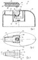
- the closure 10 consists of essentially from the cap 11, the outlet spout 13 and the O-ring 14.
- the O-ring is arranged in a groove 15.
- a Recess 21 serves to accommodate the outlet spout 13.
- This has an inlet 23 and an outlet 25.
- the inlet 23 is arranged in a roller-shaped part 27 which is transverse to Channel 28 runs, the inlet opening 23 with the Outlet opening 25 connects.
- the roller-shaped part 27 forms an axis whose ends 31 in bearing-forming recesses 33 the cap 11 are stored.
- the recesses 33 include the Ends a little over 180 degrees.
- the ends 31 of the axis are hollow, what that when assembling the closure Snap the outlet nozzle 13 easier.
- the recesses 33 have the same diameter as the ends 31 of the Axis, so that the outlet nozzle 13 practically without play can pivot.
- the radius of the trough 35 is somewhat larger than half the diameter of the ends 31 of the axis.
- the roller-shaped tell 27 a spherical section 27 '.
- the trough 35 in the cap 11 spherical, the O-ring 14, as in the figures 5 and 6, can be arranged on the outlet spout 13.
- the spherical design of section 27 'or the trough 35 has the advantage that the O-ring is not must be deformed cylindrically, but in one plane remains, with a smaller tendency for it to come out of the groove 15 pops out.
- the closure 10 has a cap 11 which can be placed on a container and an outlet spout 13 pivotably arranged in the cap 11 for closing and opening the closure 10.
- the outlet spout 13 is seated with a cylindrical axis 31 in a corresponding axle bearing 33 in the cap 11 which encloses the axis over more than 180 °.
- the inlet 23 of the outlet spout 13 is arranged in a roller-shaped part 27.
- the part 27 can have a spherical section 27 '.
- An O-shaped sealing ring 14 is arranged between the outlet spout 13 and the outlet opening 25 in the cap 11, which reliably prevents leakage even with aggressive contents.
- the ends 31 of the axis of the outlet spout 13 are hollow and therefore deformable for latching into the axle bearings 33.
- the pivotable outlet nozzle 13 is therefore securely mounted in the axle bearings 33, because the axle bearing 33 can enclose the axle 31 relatively far. This also ensures a sufficient contact pressure on the seal 14 without there being a risk that the outlet spout 13 will jump out of the axle bearings 33.
Landscapes
- Engineering & Computer Science (AREA)
- Mechanical Engineering (AREA)
- Closures For Containers (AREA)
- Closing Of Containers (AREA)
- Package Closures (AREA)
Description
- Fig. 1
- ein erstes Ausführungsbeispiel des Verschlusses in Explosionsdarstellung,
- Fig. 2
- die Kappe des Verschlusses von Figur 1 von oben gesehen,
- Fig. 3
- die Auslasstülle von unten betrachtet,
- Fig. 4
- der Verschluss mit der Auslasstülle in Öffnungsstellung,
- Fig. 5
- ein zweites Ausführungsbeispiel der Auslasstülle und
- Fig. 6
- einen Schnitt durch die Auslasstülle gemäss Figur 4.
Der Verschluss 10 weist eine auf einen Behälter aufsetzbaren Kappe 11 und eine in der Kappe 11 verschwenkbar angeordnete Auslasstülle 13 zum Schliessen und Öffnen des Verschlusses 10 auf. Die Auslasstülle 13 sitzt mit einer zylindrischen Achse 31 in einem entsprechenden, über mehr als 180° die Achse umschliessenden Achslager 33 in der Kappe 11. Der Einlass 23 der Auslasstülle 13 ist in einem walzenförmigen Teil 27 angeordnet. Der Teil 27 kann einen sphärischen Abschnitt 27' aufweisen. Bei ausgeschwenkter Auslasstülle 13 korrespondiert die in der Kappe 11 angeordnete Auslassöffnung 25 mit dem Kanal 28, so dass Füllgut aus dem Behälter durch die Auslasstülle 13 austreten kann. Zwischen der Auslasstülle 13 und der Auslassöffnung 25 in der Kappe 11 ist ein O-förmiger Dichtring 14 angeordnet, der Lekagen auch bei aggressivem Füllgut sicher verhindert. Die Enden 31 der Achse der Auslasstülle 13 sind hohl und daher zum Einklinken in die Achslager 33 verformbar. Die verschwenkbare Auslasstülle 13 wird daher in den Achslagern 33 sicher gelagert, denn das Achslager 33 kann die Achse 31 relativ weit umschliessen. Dadurch wird auch ein genügender Anpressdruck auf die Dichtung 14 sichergestellt, ohne dass Gefahr besteht, dass die Auslasstülle 13 aus den Achslagern 33 springt.
Claims (7)
- Verschluss für Behälter, mit einer auf den Behälter aufsetzbaren Kappe (11), welche eine Auslassöffnung (37) aufweist, einem im Bereich der Auslassöffnung (37) angeordneten elastischen Dichtring (14), der in der Schliessstellung die Auslassöffnung (37) der Kappe (11) umgibt, und einer einen Einlass (23) und einen Auslass (25) aufweisenden Auslasstülle (13), welche über der Auslassöffnung (37) der Kappe (11) verschwenkbar gelagert ist, wobei die Auslasstülle in der Schliessstellung die Auslassöffnung (37) der Kappe verschliesst und in der Öffnungsstellung mit der Auslassöffnung (37) der Kappe (11) kommuniziert, um Inhalt aus dem Behälter durch die Auslasstülle (13) austreten zu lassen, dadurch gekennzeichnet, dass die Auslasstülle (13) einen walzenförmigen Teil (27) aufweist, dass der Einlass (23) der Auslasstülle (13) im walzenförmigen Teil (27) angeordnet ist, und dass der walzenförmige Teil (27) praktisch in eine Mulde (35) der Kappe (11) passt und mit seinen Enden (31) in Lager bildende Ausnehmungen (33) der Kappe (11) gelagert ist.
- Verschluss für Behälter nach Anspruch 1, dadurch gekennzeichnet, dass die Ausnehmungen (33) die Enden (31) der Achse (27) um etwas mehr als 180 Grad umfassen.
- Verschluss für Behälter nach Anspruch 1 oder 2, dadurch gekennzeichnet, dass die Enden (31) der Achsen (27) hohl sind.
- Verschluss für Behälter nach einem der Ansprüche 1 bis 3, dadurch gekennzeichnet, dass der walzengförmige Teil (27) einen sphärischen Abschnitt (27') aufweist, welcher praktisch in eine sphärische Mulde (35) passt.
- Verschluss für Behälter nach einem der Ansprüche 1 bis 4, dadurch gekennzeichnet, dass der Dichtring (14) an der Kappe (11) angeordnet ist.
- Verschluss für Behälter nach einem der Ansprüche 1 bis 4, dadurch gekennzeichnet, dass der Dichtring (14) an der Auslasstülle (13) angeordnet ist.
- Verschluss für Behälter nach einem der Ansprüche 1 bis 6, dadurch gekennzeichnet, dass die Ausnehmungen (33) den gleichen Durchmesser wie die Enden (31) der Achse (27) aufweisen, und dass der Radius der Mulde (35) etwas grösser als der halbe Durchmesser der Enden (31) der Achse(27) ist.
Applications Claiming Priority (3)
| Application Number | Priority Date | Filing Date | Title |
|---|---|---|---|
| CH148497 | 1997-06-18 | ||
| CH1484/97 | 1997-06-18 | ||
| CH148497 | 1997-06-18 |
Publications (2)
| Publication Number | Publication Date |
|---|---|
| EP0913337A1 EP0913337A1 (de) | 1999-05-06 |
| EP0913337B1 true EP0913337B1 (de) | 2001-03-21 |
Family
ID=4211545
Family Applications (1)
| Application Number | Title | Priority Date | Filing Date |
|---|---|---|---|
| EP98810454A Expired - Lifetime EP0913337B1 (de) | 1997-06-18 | 1998-05-18 | Verschluss für Behälter |
Country Status (3)
| Country | Link |
|---|---|
| EP (1) | EP0913337B1 (de) |
| AT (1) | ATE199869T1 (de) |
| DE (1) | DE59803321D1 (de) |
Family Cites Families (5)
| Publication number | Priority date | Publication date | Assignee | Title |
|---|---|---|---|---|
| FR381419A (fr) * | 1907-08-30 | 1908-01-11 | Sanitaria G. M. B. H. Vormals Gretsch & C° | Bouchon pour flacon |
| US1963870A (en) * | 1932-09-15 | 1934-06-19 | Alexander A Scott | Closure for collapsible tubes |
| US4219138A (en) * | 1978-10-16 | 1980-08-26 | Polytop Corporation | Dispensing closure utilizing a sealing element supported by a washer spring |
| DE8335960U1 (de) * | 1983-12-15 | 1984-01-26 | Georg Menshen & Co Kg, 5950 Finnentrop | Zweiteiliger Verschluss fuer Behaelter |
| BR9404733A (pt) * | 1994-11-24 | 1995-08-01 | Sobral Invicta Sa | Aperfeiçoamento em tampa,com dispositivo para servir, para recipientes térmicos |
-
1998
- 1998-05-18 DE DE59803321T patent/DE59803321D1/de not_active Expired - Fee Related
- 1998-05-18 EP EP98810454A patent/EP0913337B1/de not_active Expired - Lifetime
- 1998-05-18 AT AT98810454T patent/ATE199869T1/de not_active IP Right Cessation
Also Published As
| Publication number | Publication date |
|---|---|
| EP0913337A1 (de) | 1999-05-06 |
| ATE199869T1 (de) | 2001-04-15 |
| DE59803321D1 (de) | 2002-04-18 |
Similar Documents
| Publication | Publication Date | Title |
|---|---|---|
| EP0144819B1 (de) | Isolierkanne, deren Öffnung durch einen Verschlussschieber verschliessbar ist | |
| DE2852946A1 (de) | Abzapfgeraet fuer das abzapfen kohlensaeurehaltiger getraenke aus mit einem einverleibten kohlensaeurevorratsbehaelter versehenen fluessigkeitsbehaeltern | |
| DE3333569C2 (de) | ||
| EP0287043A2 (de) | Pistole für Mehrkomponentenmaterial | |
| DE2834074A1 (de) | Geschlossener behaelter | |
| DE3407744A1 (de) | Handspritzpistole fuer ein hochdruckreinigungsgeraet | |
| EP0171462B1 (de) | Fliessgutspender | |
| DE1425896A1 (de) | Kappe fuer Aerosolbehaelter | |
| DE1757096A1 (de) | Geraet zum Gebrauch von Schminke | |
| DE69100582T2 (de) | Betätigungsvorrichtung für Ausgabeventil. | |
| WO1983003239A1 (en) | Cap intended to be placed on the central outlet opening of a liquid container | |
| DE3514172C2 (de) | ||
| DE69504044T2 (de) | Selbstschliessende abgabevorrichtung | |
| DE1143981B (de) | Vorrichtung zum Auftragen und Verteilen abgemessener Teilmengen von fliessfaehigen Stoffen, wie Schuhcreme, Tinte od. dgl. | |
| DE867190C (de) | Sicherheitsventil | |
| DE2916699C2 (de) | ||
| EP0913337A1 (de) | Verschluss für Behälter | |
| DE68917868T2 (de) | Abgabe - Vorrichtung und Verfahren. | |
| DE69214140T2 (de) | Hermetischen Verschluss für Behälter | |
| DE1575852C3 (de) | ||
| DE10042206C2 (de) | Kanne | |
| WO2003024827A1 (de) | Abgabeverschluss für fliessfähiges gut enthaltende behälter | |
| DE20108329U1 (de) | Sprühdose | |
| DE2617862B2 (de) | Klebstoffauftragsstift | |
| DE2450324A1 (de) | Kugelhahn |
Legal Events
| Date | Code | Title | Description |
|---|---|---|---|
| PUAI | Public reference made under article 153(3) epc to a published international application that has entered the european phase |
Free format text: ORIGINAL CODE: 0009012 |
|
| AK | Designated contracting states |
Kind code of ref document: A1 Designated state(s): AT BE CH DE ES FR GB IT LI NL PT |
|
| AX | Request for extension of the european patent |
Free format text: AL;LT;LV;MK;RO;SI |
|
| 17P | Request for examination filed |
Effective date: 19990626 |
|
| AKX | Designation fees paid | ||
| REG | Reference to a national code |
Ref country code: DE Ref legal event code: 8566 |
|
| 17Q | First examination report despatched |
Effective date: 20000112 |
|
| RBV | Designated contracting states (corrected) |
Designated state(s): AT CH DE FR LI |
|
| RBV | Designated contracting states (corrected) |
Designated state(s): AT BE CH DE ES FR GB IT LI NL PT |
|
| GRAG | Despatch of communication of intention to grant |
Free format text: ORIGINAL CODE: EPIDOS AGRA |
|
| GRAG | Despatch of communication of intention to grant |
Free format text: ORIGINAL CODE: EPIDOS AGRA |
|
| GRAH | Despatch of communication of intention to grant a patent |
Free format text: ORIGINAL CODE: EPIDOS IGRA |
|
| RAP1 | Party data changed (applicant data changed or rights of an application transferred) |
Owner name: ALPLA WERKE ALWIN LEHNER GMBH & CO. KG |
|
| GRAH | Despatch of communication of intention to grant a patent |
Free format text: ORIGINAL CODE: EPIDOS IGRA |
|
| GRAA | (expected) grant |
Free format text: ORIGINAL CODE: 0009210 |
|
| AK | Designated contracting states |
Kind code of ref document: B1 Designated state(s): AT BE CH DE ES FR GB IT LI NL PT |
|
| PG25 | Lapsed in a contracting state [announced via postgrant information from national office to epo] |
Ref country code: NL Free format text: LAPSE BECAUSE OF FAILURE TO SUBMIT A TRANSLATION OF THE DESCRIPTION OR TO PAY THE FEE WITHIN THE PRESCRIBED TIME-LIMIT Effective date: 20010321 Ref country code: IT Free format text: LAPSE BECAUSE OF FAILURE TO SUBMIT A TRANSLATION OF THE DESCRIPTION OR TO PAY THE FEE WITHIN THE PRE;WARNING: LAPSES OF ITALIAN PATENTS WITH EFFECTIVE DATE BEFORE 2007 MAY HAVE OCCURRED AT ANY TIME BEFORE 2007. THE CORRECT EFFECTIVE DATE MAY BE DIFFERENT FROM THE ONE RECORDED.SCRIBED TIME-LIMIT Effective date: 20010321 Ref country code: FR Free format text: LAPSE BECAUSE OF FAILURE TO SUBMIT A TRANSLATION OF THE DESCRIPTION OR TO PAY THE FEE WITHIN THE PRESCRIBED TIME-LIMIT Effective date: 20010321 |
|
| REF | Corresponds to: |
Ref document number: 199869 Country of ref document: AT Date of ref document: 20010415 Kind code of ref document: T |
|
| REG | Reference to a national code |
Ref country code: CH Ref legal event code: EP |
|
| GBT | Gb: translation of ep patent filed (gb section 77(6)(a)/1977) |
Effective date: 20010321 |
|
| PG25 | Lapsed in a contracting state [announced via postgrant information from national office to epo] |
Ref country code: AT Free format text: LAPSE BECAUSE OF NON-PAYMENT OF DUE FEES Effective date: 20010518 |
|
| PG25 | Lapsed in a contracting state [announced via postgrant information from national office to epo] |
Ref country code: BE Free format text: LAPSE BECAUSE OF NON-PAYMENT OF DUE FEES Effective date: 20010531 |
|
| PG25 | Lapsed in a contracting state [announced via postgrant information from national office to epo] |
Ref country code: PT Free format text: LAPSE BECAUSE OF FAILURE TO SUBMIT A TRANSLATION OF THE DESCRIPTION OR TO PAY THE FEE WITHIN THE PRESCRIBED TIME-LIMIT Effective date: 20010621 |
|
| EN | Fr: translation not filed | ||
| NLV1 | Nl: lapsed or annulled due to failure to fulfill the requirements of art. 29p and 29m of the patents act | ||
| PG25 | Lapsed in a contracting state [announced via postgrant information from national office to epo] |
Ref country code: ES Free format text: LAPSE BECAUSE OF FAILURE TO SUBMIT A TRANSLATION OF THE DESCRIPTION OR TO PAY THE FEE WITHIN THE PRESCRIBED TIME-LIMIT Effective date: 20010927 |
|
| BERE | Be: lapsed |
Owner name: ALPLA WERKE ALWIN LEHNER G.M.B.H. & CO. K.G. Effective date: 20010531 |
|
| REG | Reference to a national code |
Ref country code: GB Ref legal event code: IF02 |
|
| PLBE | No opposition filed within time limit |
Free format text: ORIGINAL CODE: 0009261 |
|
| STAA | Information on the status of an ep patent application or granted ep patent |
Free format text: STATUS: NO OPPOSITION FILED WITHIN TIME LIMIT |
|
| 26N | No opposition filed | ||
| PG25 | Lapsed in a contracting state [announced via postgrant information from national office to epo] |
Ref country code: DE Free format text: LAPSE BECAUSE OF NON-PAYMENT OF DUE FEES Effective date: 20020401 |
|
| REF | Corresponds to: |
Ref document number: 59803321 Country of ref document: DE Date of ref document: 20020418 |
|
| PG25 | Lapsed in a contracting state [announced via postgrant information from national office to epo] |
Ref country code: GB Free format text: LAPSE BECAUSE OF NON-PAYMENT OF DUE FEES Effective date: 20020518 |
|
| PG25 | Lapsed in a contracting state [announced via postgrant information from national office to epo] |
Ref country code: LI Free format text: LAPSE BECAUSE OF NON-PAYMENT OF DUE FEES Effective date: 20020531 Ref country code: CH Free format text: LAPSE BECAUSE OF NON-PAYMENT OF DUE FEES Effective date: 20020531 |
|
| GBPC | Gb: european patent ceased through non-payment of renewal fee |
Effective date: 20020518 |
|
| REG | Reference to a national code |
Ref country code: CH Ref legal event code: PL |