EP0913645A1 - Brennkammer für eine Turbomaschine - Google Patents
Brennkammer für eine Turbomaschine Download PDFInfo
- Publication number
- EP0913645A1 EP0913645A1 EP98402697A EP98402697A EP0913645A1 EP 0913645 A1 EP0913645 A1 EP 0913645A1 EP 98402697 A EP98402697 A EP 98402697A EP 98402697 A EP98402697 A EP 98402697A EP 0913645 A1 EP0913645 A1 EP 0913645A1
- Authority
- EP
- European Patent Office
- Prior art keywords
- injectors
- combustion chamber
- holes
- row
- walls
- Prior art date
- Legal status (The legal status is an assumption and is not a legal conclusion. Google has not performed a legal analysis and makes no representation as to the accuracy of the status listed.)
- Granted
Links
- 238000002485 combustion reaction Methods 0.000 title claims abstract description 38
- 238000010790 dilution Methods 0.000 claims abstract description 24
- 239000012895 dilution Substances 0.000 claims abstract description 24
- 239000000446 fuel Substances 0.000 claims abstract description 15
- 238000001816 cooling Methods 0.000 claims abstract description 10
- 230000000295 complement effect Effects 0.000 claims abstract description 4
- 239000000567 combustion gas Substances 0.000 claims description 2
- 238000011144 upstream manufacturing Methods 0.000 claims description 2
- MWUXSHHQAYIFBG-UHFFFAOYSA-N nitrogen oxide Inorganic materials O=[N] MWUXSHHQAYIFBG-UHFFFAOYSA-N 0.000 description 12
- 230000006835 compression Effects 0.000 description 2
- 238000007906 compression Methods 0.000 description 2
- 239000007789 gas Substances 0.000 description 2
- 238000004519 manufacturing process Methods 0.000 description 2
- 238000003915 air pollution Methods 0.000 description 1
- 238000009434 installation Methods 0.000 description 1
- 239000007800 oxidant agent Substances 0.000 description 1
- 239000000243 solution Substances 0.000 description 1
- 238000005507 spraying Methods 0.000 description 1
- 230000035882 stress Effects 0.000 description 1
- 230000008646 thermal stress Effects 0.000 description 1
- 238000009834 vaporization Methods 0.000 description 1
- 230000008016 vaporization Effects 0.000 description 1
Images


Classifications
-
- F—MECHANICAL ENGINEERING; LIGHTING; HEATING; WEAPONS; BLASTING
- F23—COMBUSTION APPARATUS; COMBUSTION PROCESSES
- F23R—GENERATING COMBUSTION PRODUCTS OF HIGH PRESSURE OR HIGH VELOCITY, e.g. GAS-TURBINE COMBUSTION CHAMBERS
- F23R3/00—Continuous combustion chambers using liquid or gaseous fuel
- F23R3/02—Continuous combustion chambers using liquid or gaseous fuel characterised by the air-flow or gas-flow configuration
- F23R3/04—Air inlet arrangements
- F23R3/06—Arrangement of apertures along the flame tube
-
- F—MECHANICAL ENGINEERING; LIGHTING; HEATING; WEAPONS; BLASTING
- F23—COMBUSTION APPARATUS; COMBUSTION PROCESSES
- F23R—GENERATING COMBUSTION PRODUCTS OF HIGH PRESSURE OR HIGH VELOCITY, e.g. GAS-TURBINE COMBUSTION CHAMBERS
- F23R3/00—Continuous combustion chambers using liquid or gaseous fuel
- F23R3/02—Continuous combustion chambers using liquid or gaseous fuel characterised by the air-flow or gas-flow configuration
- F23R3/04—Air inlet arrangements
-
- F—MECHANICAL ENGINEERING; LIGHTING; HEATING; WEAPONS; BLASTING
- F23—COMBUSTION APPARATUS; COMBUSTION PROCESSES
- F23R—GENERATING COMBUSTION PRODUCTS OF HIGH PRESSURE OR HIGH VELOCITY, e.g. GAS-TURBINE COMBUSTION CHAMBERS
- F23R3/00—Continuous combustion chambers using liquid or gaseous fuel
- F23R3/28—Continuous combustion chambers using liquid or gaseous fuel characterised by the fuel supply
- F23R3/34—Feeding into different combustion zones
-
- Y—GENERAL TAGGING OF NEW TECHNOLOGICAL DEVELOPMENTS; GENERAL TAGGING OF CROSS-SECTIONAL TECHNOLOGIES SPANNING OVER SEVERAL SECTIONS OF THE IPC; TECHNICAL SUBJECTS COVERED BY FORMER USPC CROSS-REFERENCE ART COLLECTIONS [XRACs] AND DIGESTS
- Y02—TECHNOLOGIES OR APPLICATIONS FOR MITIGATION OR ADAPTATION AGAINST CLIMATE CHANGE
- Y02T—CLIMATE CHANGE MITIGATION TECHNOLOGIES RELATED TO TRANSPORTATION
- Y02T50/00—Aeronautics or air transport
- Y02T50/60—Efficient propulsion technologies, e.g. for aircraft
Definitions
- nitrogen oxides are a function of the richness, the temperatures, compression ratio and duration of combustion. It occurs in particular in the areas of the combustion chamber where the wealth is close to the stoichiometric ratio and is all the more important that the temperature and compression ratio are high. Also, it is advisable to decrease the time of the stay in these zones critical or diminish their importance.
- combustion chambers in which the injectors are divided into two groups, the injectors of one of the groups being intended for fuel supply during a first operating mode, such as idling speed, and the injectors the other group being intended for fuel supply during a second operating mode, such as full throttle.
- the two groups of injectors are arranged concentrically in the back of the room and are separated physically by dividing plates which extend inwards of the chamber, in order to define two sections of different length in the combustion chamber, the shortest section being used at engine speed full throttle.
- combustion chambers known as double-headed, are complex and heavy for a given maximum thrust, because the injectors of one of the heads are out of operation during a game during the flight and during takeoff.
- the separator plates must withstand mechanical stress and very important and often asymmetrical thermal. They are by the even made it difficult to design and manufacture.
- the present invention proposes another solution, simpler than the previous ones and which has other advantages for reducing nitrogen oxide emissions.
- the invention therefore relates to a combustion chamber comprising two mutually spaced annular walls, joined in upstream by a bottom and delimiting with it an enclosure of combustion, an axis of sensitive symmetry of said annular walls, fuel injectors arranged in holes in the bottom, said injectors being permanently supplied with fuel during of the operation of said combustion chamber, passages of admission of complementary air formed in said bottom, holes primers formed in said walls and intended to introduce a flow air in the primary area of the enclosure, dilution holes provided in said walls downstream of the primary holes and intended to introduce the air in the dilution zone of the enclosure, and the orifices of cooling of the walls of the dilution zone, said walls defining downstream an annular outlet for the evacuation of the gases of combustion outside said enclosure.
- the proportions of injected air are substantially 26% at the injectors, 7.5% through the passages, 22.3% through the primary holes, 24.7% through dilution holes and 19.5% through orifices cooling, compared to the total air flow injected into the enclosure.
- the two rows of injectors introduce substantially the same amount of air and fuel.
- the proportion of air injected through the passages is distributed from the as follows: substantially 1.6% of the total flow is introduced by the internal group passing through, 3.5% by the middle group and 2.4% by the external group.
- the number of dilution holes is twice the number of primary holes.
- the number of primary holes per ferrule is double the number of injectors in each row of injectors.
- the dilution holes in an annular wall are located in a transverse plane away from the transverse plane containing the holes primaries of the same wall, from a distance d less than the distance D separating two adjacent primary holes.
- the ratio of length L to thickness H is greater or equal to 1.2.
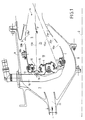
- the gas turbine combustion chamber shown in the drawings includes an internal annular wall 1 of axis 2, a wall external annular 3 of axis 2 and a bottom 4 which delimits with these two walls annular 1 and 3 a combustion chamber 5 which comprises at ends of walls 1 and 3 remote from bottom 4 an annular outlet 6, axis 2, for the evacuation of combustion gases to a turbine disposed downstream of the combustion chamber 5.
- the latter is placed in a space 7 delimited by an internal envelope 8 and an envelope external 9 annulars, axis 2, and into which is admitted (arrow G) a oxidizer under pressure, usually air pressurized by a compressor driven by the turbine.
- the bottom 4 has a plurality of orifices 10 in each of which is arranged a fuel injector 11 of the aeromechanical type associated with a twist 12 for the introduction of an air flow participating in the vaporization and spraying of fuel and to a bowl 13 flared towards the outlet 6 and forming part of the bottom 4 of the combustion chamber.
- the injectors of fuel 11 are distributed in two concentric rows 14a, 14b, of axis 2.
- the two rows of injectors 14a, 14b have the same number N of injectors regularly distributed circumferentially around the axis 2 and in the same longitudinal plane P 1 , P 2 , containing the axis 2.
- the axes 15a of the injectors the internal row 14a are directed towards the outlet 6 of the enclosure 5, and the axes 15b of the injectors of the external row 14b are also directed towards the outlet 6, so that the axes 15a, 15b of two superimposed injectors 11 are substantially cut in the region of the outlet 6.
- the two superimposed injectors are connected to the same ramp 16 containing fuel.
- the injectors 11 of the two rows 14a, 14b are substantially equidistant from output 6 and are supplied at the same time and continuously during operation. In addition, there are no plans to separator plates between the two rows 14a, 14b of injectors.
- passages for the introduction with a complementary air are divided into three groups: one internal passage group 17a located between the internal annular wall 1 and the bowls of the injectors of the internal row 14a, an external group of passages 17b located between the outer annular wall 3 and the bowls of the injectors of the external row 14a, and a middle passage group 17c located between the bowls of the injectors of the internal row 14a and the bowls of the injectors of the outer row 14b.
- the internal 1 and external 3 walls also comprise primary holes 18a, 18b for the introduction of an air flow in the primary zone 19 of the enclosure 5 which are regularly distributed in transverse planes P3, P4 perpendicular to the axis of symmetry 2, and dilution holes 20a, 20b for the introduction of a dilution air flow in the dilution zone 21 of the enclosure 5 which are regularly distributed in transverse planes P 5 , P 6 perpendicular to the axis of symmetry 2.
- the number of primary holes 18a, 18b in each of the walls 1 and 3 is double the number of injectors N in each row injectors 14a, 14b, while the number of dilution holes 20a, 20b is double the number of primary holes.
- the distance d 1 which separates the two planes P4, and P6 is less than the distance D 1 of two consecutive primary holes 18b of the external wall 3.
- the distance d2 which separates the two planes P 3 and P 5 is less than the distance D 2 of two consecutive primary holes 18a of the internal wall 1.
- this distance d2 is less than the distance d 1 and substantially equal to half of this last.
- the internal walls 1 and external 3 further comprise cooling orifices 21a, 21b for the introduction of air for cooling these walls.
- the air flow G introduced into space 7 feeds the enclosure of combustion 5 according to the following distribution shown in FIG. 3.
- This distribution of air flow provides a ratio equivalence of the injector at 1.8 at full throttle and an equivalence ratio in the primary zone less than 0.86 with a richness in the enclosure at full throttle of 32.6% o, knowing that the equivalence ratio is the ratio of the wealth in the area compared to the stoichiometric wealth, the wealth in the area being the ratio between fuel flow and flow air in the area.
Landscapes
- Engineering & Computer Science (AREA)
- Chemical & Material Sciences (AREA)
- Combustion & Propulsion (AREA)
- Mechanical Engineering (AREA)
- General Engineering & Computer Science (AREA)
- Fuel-Injection Apparatus (AREA)
- Combustion Methods Of Internal-Combustion Engines (AREA)
Applications Claiming Priority (2)
| Application Number | Priority Date | Filing Date | Title |
|---|---|---|---|
| FR9713549A FR2770283B1 (fr) | 1997-10-29 | 1997-10-29 | Chambre de combustion pour turbomachine |
| FR9713549 | 1997-10-29 |
Publications (2)
| Publication Number | Publication Date |
|---|---|
| EP0913645A1 true EP0913645A1 (de) | 1999-05-06 |
| EP0913645B1 EP0913645B1 (de) | 2004-01-07 |
Family
ID=9512771
Family Applications (1)
| Application Number | Title | Priority Date | Filing Date |
|---|---|---|---|
| EP98402697A Expired - Lifetime EP0913645B1 (de) | 1997-10-29 | 1998-10-29 | Brennkammer für eine Turbomaschine |
Country Status (7)
| Country | Link |
|---|---|
| US (1) | US6070412A (de) |
| EP (1) | EP0913645B1 (de) |
| JP (1) | JP3714806B2 (de) |
| DE (1) | DE69820967T2 (de) |
| ES (1) | ES2210689T3 (de) |
| FR (1) | FR2770283B1 (de) |
| RU (1) | RU2151343C1 (de) |
Cited By (2)
| Publication number | Priority date | Publication date | Assignee | Title |
|---|---|---|---|---|
| EP1150072A3 (de) * | 2000-04-27 | 2001-12-19 | Rolls-Royce Deutschland Ltd & Co KG | Gasturbinenbrennkammer mit Zuleitungsöffnung |
| FR2922629A1 (fr) * | 2007-10-22 | 2009-04-24 | Snecma Sa | Chambre de combustion a dilution optimisee et turbomachine en etant munie |
Families Citing this family (37)
| Publication number | Priority date | Publication date | Assignee | Title |
|---|---|---|---|---|
| GB2319078B (en) * | 1996-11-08 | 1999-11-03 | Europ Gas Turbines Ltd | Combustor arrangement |
| US6474070B1 (en) * | 1998-06-10 | 2002-11-05 | General Electric Company | Rich double dome combustor |
| US6279323B1 (en) * | 1999-11-01 | 2001-08-28 | General Electric Company | Low emissions combustor |
| US6260359B1 (en) * | 1999-11-01 | 2001-07-17 | General Electric Company | Offset dilution combustor liner |
| FR2829228B1 (fr) * | 2001-08-28 | 2005-07-15 | Snecma Moteurs | Chambre de combustion annulaire a double tete etagee |
| CN100529547C (zh) * | 2002-01-14 | 2009-08-19 | 阿尔斯通技术有限公司 | 用于燃气轮机的环形燃烧室的燃烧器装置 |
| US6675587B2 (en) * | 2002-03-21 | 2004-01-13 | United Technologies Corporation | Counter swirl annular combustor |
| RU2226652C2 (ru) * | 2002-05-28 | 2004-04-10 | Открытое акционерное общество "Авиадвигатель" | Камера сгорания газотурбинного двигателя |
| US7836699B2 (en) * | 2005-12-20 | 2010-11-23 | United Technologies Corporation | Combustor nozzle |
| US7926284B2 (en) * | 2006-11-30 | 2011-04-19 | Honeywell International Inc. | Quench jet arrangement for annular rich-quench-lean gas turbine combustors |
| FR2922630B1 (fr) * | 2007-10-22 | 2015-11-13 | Snecma | Paroi de chambre de combustion a dilution et refroidissement optimises,chambre de combustion et turbomachine en etant munies |
| US8616004B2 (en) * | 2007-11-29 | 2013-12-31 | Honeywell International Inc. | Quench jet arrangement for annular rich-quench-lean gas turbine combustors |
| US8127554B2 (en) * | 2007-11-29 | 2012-03-06 | Honeywell International Inc. | Quench jet arrangement for annular rich-quench-lean gas turbine combustors |
| US20090165435A1 (en) * | 2008-01-02 | 2009-07-02 | Michal Koranek | Dual fuel can combustor with automatic liquid fuel purge |
| US8171740B2 (en) * | 2009-02-27 | 2012-05-08 | Honeywell International Inc. | Annular rich-quench-lean gas turbine combustors with plunged holes |
| US8739546B2 (en) | 2009-08-31 | 2014-06-03 | United Technologies Corporation | Gas turbine combustor with quench wake control |
| FR2950415B1 (fr) * | 2009-09-21 | 2011-10-14 | Snecma | Chambre de combustion de turbomachine aeronautique avec trous de combustion decales ou de debits differents |
| US8443610B2 (en) | 2009-11-25 | 2013-05-21 | United Technologies Corporation | Low emission gas turbine combustor |
| US9416970B2 (en) * | 2009-11-30 | 2016-08-16 | United Technologies Corporation | Combustor heat panel arrangement having holes offset from seams of a radially opposing heat panel |
| US8966877B2 (en) | 2010-01-29 | 2015-03-03 | United Technologies Corporation | Gas turbine combustor with variable airflow |
| US9068751B2 (en) * | 2010-01-29 | 2015-06-30 | United Technologies Corporation | Gas turbine combustor with staged combustion |
| FR2958013B1 (fr) * | 2010-03-26 | 2014-06-20 | Snecma | Chambre de combustion de turbomachine a compresseur centrifuge sans deflecteur |
| US9958162B2 (en) | 2011-01-24 | 2018-05-01 | United Technologies Corporation | Combustor assembly for a turbine engine |
| US9068748B2 (en) | 2011-01-24 | 2015-06-30 | United Technologies Corporation | Axial stage combustor for gas turbine engines |
| US8479521B2 (en) | 2011-01-24 | 2013-07-09 | United Technologies Corporation | Gas turbine combustor with liner air admission holes associated with interspersed main and pilot swirler assemblies |
| FR2980553B1 (fr) * | 2011-09-26 | 2013-09-20 | Snecma | Chambre de combustion de turbomachine |
| US20130276450A1 (en) * | 2012-04-24 | 2013-10-24 | General Electric Company | Combustor apparatus for stoichiometric combustion |
| US20140083111A1 (en) * | 2012-09-25 | 2014-03-27 | United Technologies Corporation | Gas turbine asymmetric fuel nozzle combustor |
| WO2015100346A1 (en) | 2013-12-23 | 2015-07-02 | United Technologies Corporation | Multi-streamed dilution hole configuration for a gas turbine engine |
| FR3024755B1 (fr) * | 2014-08-08 | 2019-06-21 | Safran Aircraft Engines | Hybridation des compresseurs d'un turboreacteur |
| DE102016219424A1 (de) * | 2016-10-06 | 2018-04-12 | Rolls-Royce Deutschland Ltd & Co Kg | Brennkammeranordnung einer Gasturbine sowie Fluggasturbine |
| US10816202B2 (en) * | 2017-11-28 | 2020-10-27 | General Electric Company | Combustor liner for a gas turbine engine and an associated method thereof |
| US11255543B2 (en) | 2018-08-07 | 2022-02-22 | General Electric Company | Dilution structure for gas turbine engine combustor |
| DE102020128661A1 (de) | 2020-10-30 | 2022-05-05 | Rolls-Royce Deutschland Ltd & Co Kg | Düse für eine Brennkammer eines Triebwerks mit wenigstens zwei Düsenköpfen |
| US12173900B2 (en) * | 2021-11-11 | 2024-12-24 | General Electric Company | Combustion liner having a dilution passage |
| US11774100B2 (en) * | 2022-01-14 | 2023-10-03 | General Electric Company | Combustor fuel nozzle assembly |
| WO2024248664A2 (ru) * | 2023-05-28 | 2024-12-05 | Владислав Викторович МАТАФОНОВ | Камера сгорания газотурбинного двигателя |
Citations (3)
| Publication number | Priority date | Publication date | Assignee | Title |
|---|---|---|---|---|
| EP0488557A1 (de) * | 1990-11-26 | 1992-06-03 | General Electric Company | Zwillingsbrennkammer |
| EP0491478A1 (de) * | 1990-12-17 | 1992-06-24 | General Electric Company | Zwillingsbrennkammer und ihre Funktion |
| US5284019A (en) * | 1990-06-12 | 1994-02-08 | The United States Of America As Represented By The Secretary Of The Air Force | Double dome, single anular combustor with daisy mixer |
Family Cites Families (18)
| Publication number | Priority date | Publication date | Assignee | Title |
|---|---|---|---|---|
| FR2402068A1 (fr) * | 1977-09-02 | 1979-03-30 | Snecma | Chambre de combustion anti-pollution |
| US4365470A (en) * | 1980-04-02 | 1982-12-28 | United Technologies Corporation | Fuel nozzle guide and seal for a gas turbine engine |
| US5220795A (en) * | 1991-04-16 | 1993-06-22 | General Electric Company | Method and apparatus for injecting dilution air |
| CA2070518C (en) * | 1991-07-01 | 2001-10-02 | Adrian Mark Ablett | Combustor dome assembly |
| FR2686683B1 (fr) * | 1992-01-28 | 1994-04-01 | Snecma | Turbomachine a chambre de combustion demontable. |
| FR2691235B1 (fr) * | 1992-05-13 | 1995-07-07 | Snecma | Chambre de combustion comprenant un ensemble separateur des gaz. |
| FR2706021B1 (fr) * | 1993-06-03 | 1995-07-07 | Snecma | Chambre de combustion comprenant un ensemble séparateur de gaz. |
| FR2706588B1 (fr) * | 1993-06-16 | 1995-07-21 | Snecma | Système d'injection de carburant pour chambre de combustion. |
| FR2710968B1 (fr) * | 1993-10-06 | 1995-11-03 | Snecma | Chambre de combustion à double paroi. |
| FR2714152B1 (fr) * | 1993-12-22 | 1996-01-19 | Snecma | Dispositif de fixation d'une tuile de protection thermique dans une chambre de combustion. |
| FR2714154B1 (fr) * | 1993-12-22 | 1996-01-19 | Snecma | Chambre de combustion comportant une paroi munie d'une multiperforation. |
| FR2717250B1 (fr) * | 1994-03-10 | 1996-04-12 | Snecma | Système d'injection à prémélange. |
| FR2721694B1 (fr) * | 1994-06-22 | 1996-07-19 | Snecma | Refroidissement de l'injecteur de décollage d'une chambre de combustion à deux têtes. |
| FR2723177B1 (fr) * | 1994-07-27 | 1996-09-06 | Snecma | Chambre de combustion comportant une double paroi |
| FR2727192B1 (fr) * | 1994-11-23 | 1996-12-20 | Snecma | Systeme d'injection d'une chambre de combustion a deux tetes |
| FR2727193B1 (fr) * | 1994-11-23 | 1996-12-20 | Snecma | Chambre de combustion a deux tetes fonctionnant du ralenti au plein gaz |
| FR2730555B1 (fr) * | 1995-02-15 | 1997-03-14 | Snecma | Ensemble d'injection de carburant pour chambre de combustion de turbines a gaz |
| FR2733582B1 (fr) * | 1995-04-26 | 1997-06-06 | Snecma | Chambre de combustion comportant une multiperforation d'inclinaison axiale et tangentielle variable |
-
1997
- 1997-10-29 FR FR9713549A patent/FR2770283B1/fr not_active Expired - Fee Related
-
1998
- 1998-10-28 RU RU98119465/06A patent/RU2151343C1/ru active
- 1998-10-28 JP JP30741498A patent/JP3714806B2/ja not_active Expired - Fee Related
- 1998-10-28 US US09/179,896 patent/US6070412A/en not_active Expired - Lifetime
- 1998-10-29 ES ES98402697T patent/ES2210689T3/es not_active Expired - Lifetime
- 1998-10-29 EP EP98402697A patent/EP0913645B1/de not_active Expired - Lifetime
- 1998-10-29 DE DE69820967T patent/DE69820967T2/de not_active Expired - Lifetime
Patent Citations (3)
| Publication number | Priority date | Publication date | Assignee | Title |
|---|---|---|---|---|
| US5284019A (en) * | 1990-06-12 | 1994-02-08 | The United States Of America As Represented By The Secretary Of The Air Force | Double dome, single anular combustor with daisy mixer |
| EP0488557A1 (de) * | 1990-11-26 | 1992-06-03 | General Electric Company | Zwillingsbrennkammer |
| EP0491478A1 (de) * | 1990-12-17 | 1992-06-24 | General Electric Company | Zwillingsbrennkammer und ihre Funktion |
Cited By (4)
| Publication number | Priority date | Publication date | Assignee | Title |
|---|---|---|---|---|
| EP1150072A3 (de) * | 2000-04-27 | 2001-12-19 | Rolls-Royce Deutschland Ltd & Co KG | Gasturbinenbrennkammer mit Zuleitungsöffnung |
| FR2922629A1 (fr) * | 2007-10-22 | 2009-04-24 | Snecma Sa | Chambre de combustion a dilution optimisee et turbomachine en etant munie |
| RU2474763C2 (ru) * | 2007-10-22 | 2013-02-10 | Снекма | Камера сгорания с оптимизированным разбавлением и турбомашина, снабженная такой камерой сгорания |
| EP2053312A3 (de) * | 2007-10-22 | 2014-10-29 | Snecma | Brennkammer mit optimierter Verdünnung und damit ausgestattetes Turbotriebwerk |
Also Published As
| Publication number | Publication date |
|---|---|
| EP0913645B1 (de) | 2004-01-07 |
| US6070412A (en) | 2000-06-06 |
| FR2770283B1 (fr) | 1999-11-19 |
| FR2770283A1 (fr) | 1999-04-30 |
| RU2151343C1 (ru) | 2000-06-20 |
| JP3714806B2 (ja) | 2005-11-09 |
| ES2210689T3 (es) | 2004-07-01 |
| JPH11201453A (ja) | 1999-07-30 |
| DE69820967D1 (de) | 2004-02-12 |
| DE69820967T2 (de) | 2004-12-09 |
Similar Documents
| Publication | Publication Date | Title |
|---|---|---|
| EP0913645B1 (de) | Brennkammer für eine Turbomaschine | |
| EP2771618B1 (de) | Ringförmige brennkammerwand mit verbesserter kühlung an den primär- und/oder verdünnungsluftlöchern | |
| CA2588952C (fr) | Chambre de combustion d'une turbomachine | |
| EP1793168B1 (de) | Einspritzvorrichtung für eine Mischung von Luft und Kraftstoff, Turbomaschine und Brennkammer mit einer derartigen Vorrichtung | |
| FR2635577A1 (fr) | Chambre de combustion pour moteur a turbine a gaz | |
| FR2660736A1 (fr) | Assemblage de combustion etagee pauvre. | |
| CA2641989A1 (fr) | Chambre de combustion a dilution optimisee et turbomachine en etant munie | |
| EP1288579B1 (de) | Gestufte zweiköpfige Ringbrennkammer | |
| CA2899508C (fr) | Ensemble de combustion de turbomachine comprenant un circuit d'alimentation de carburant ameliore | |
| FR2931537A1 (fr) | Procedes et systemes pour reduire la dynamique de combustion | |
| CN113790463A (zh) | 蜗壳驻涡燃烧器组件 | |
| CA2642059C (fr) | Paroi de chambre de combustion a dilution et refroidissement optimises, chambre de combustion et turbomachine en etant munies | |
| FR2672667A1 (fr) | Chambre de combustion pour turboreacteur a faible niveau d'emissions polluantes. | |
| CA2843690C (fr) | Paroi de chambre de combustion | |
| FR2695460A1 (fr) | Chambre de combustion de turbomachine à plusieurs injecteurs. | |
| FR2694799A1 (fr) | Chambre de combustion annulaire conventionnelle à plusieurs injecteurs. | |
| EP0727615A1 (de) | Einspritzdüse für die Brennkammer einer Gasturbine | |
| FR2942640A1 (fr) | Chambre de post-combustion pour turbomachine | |
| FR2618528A1 (fr) | Perfectionnements aux chambres de combustion auxiliaires, pour moteurs a combustion interne suralimentes, et moteurs a combustion interne equipes d'une telle chambre | |
| FR3039220A1 (fr) | Dipositif de postcombustion pour turboreacteur | |
| FR3061948A1 (fr) | Chambre de combustion de turbomachine a haute permeabilite | |
| FR3121975A1 (fr) | Dispositif accroche-flammes pour poscombustion de turboréacteur comprenant des bras de longueurs différentes | |
| WO2013045802A1 (fr) | Chambre de combustion de turbomachine | |
| FR3108966A1 (fr) | Chambre de combustion comportant une paroi comprenant un conduit de refroidissement entre une première cloison et une deuxième cloison | |
| WO2026022429A1 (fr) | Dispositif d'injection de carburant |
Legal Events
| Date | Code | Title | Description |
|---|---|---|---|
| PUAI | Public reference made under article 153(3) epc to a published international application that has entered the european phase |
Free format text: ORIGINAL CODE: 0009012 |
|
| 17P | Request for examination filed |
Effective date: 19981121 |
|
| AK | Designated contracting states |
Kind code of ref document: A1 Designated state(s): DE ES FR GB IT SE |
|
| AX | Request for extension of the european patent |
Free format text: AL;LT;LV;MK;RO;SI |
|
| AKX | Designation fees paid |
Free format text: DE ES FR GB IT SE |
|
| 17Q | First examination report despatched |
Effective date: 20021220 |
|
| GRAH | Despatch of communication of intention to grant a patent |
Free format text: ORIGINAL CODE: EPIDOS IGRA |
|
| GRAS | Grant fee paid |
Free format text: ORIGINAL CODE: EPIDOSNIGR3 |
|
| GRAA | (expected) grant |
Free format text: ORIGINAL CODE: 0009210 |
|
| RAP1 | Party data changed (applicant data changed or rights of an application transferred) |
Owner name: SNECMA MOTEURS |
|
| AK | Designated contracting states |
Kind code of ref document: B1 Designated state(s): DE ES FR GB IT SE |
|
| REG | Reference to a national code |
Ref country code: GB Ref legal event code: FG4D Free format text: NOT ENGLISH |
|
| REG | Reference to a national code |
Ref country code: SE Ref legal event code: TRGR |
|
| REF | Corresponds to: |
Ref document number: 69820967 Country of ref document: DE Date of ref document: 20040212 Kind code of ref document: P |
|
| GBT | Gb: translation of ep patent filed (gb section 77(6)(a)/1977) |
Effective date: 20040128 |
|
| REG | Reference to a national code |
Ref country code: ES Ref legal event code: FG2A Ref document number: 2210689 Country of ref document: ES Kind code of ref document: T3 |
|
| PLBE | No opposition filed within time limit |
Free format text: ORIGINAL CODE: 0009261 |
|
| STAA | Information on the status of an ep patent application or granted ep patent |
Free format text: STATUS: NO OPPOSITION FILED WITHIN TIME LIMIT |
|
| 26N | No opposition filed |
Effective date: 20041008 |
|
| REG | Reference to a national code |
Ref country code: FR Ref legal event code: CD |
|
| PGFP | Annual fee paid to national office [announced via postgrant information from national office to epo] |
Ref country code: SE Payment date: 20070925 Year of fee payment: 10 Ref country code: ES Payment date: 20071008 Year of fee payment: 10 |
|
| EUG | Se: european patent has lapsed | ||
| REG | Reference to a national code |
Ref country code: ES Ref legal event code: FD2A Effective date: 20081030 |
|
| PG25 | Lapsed in a contracting state [announced via postgrant information from national office to epo] |
Ref country code: ES Free format text: LAPSE BECAUSE OF NON-PAYMENT OF DUE FEES Effective date: 20081030 |
|
| PG25 | Lapsed in a contracting state [announced via postgrant information from national office to epo] |
Ref country code: SE Free format text: LAPSE BECAUSE OF NON-PAYMENT OF DUE FEES Effective date: 20081030 |
|
| REG | Reference to a national code |
Ref country code: FR Ref legal event code: PLFP Year of fee payment: 18 |
|
| REG | Reference to a national code |
Ref country code: FR Ref legal event code: PLFP Year of fee payment: 19 |
|
| REG | Reference to a national code |
Ref country code: FR Ref legal event code: PLFP Year of fee payment: 20 |
|
| PGFP | Annual fee paid to national office [announced via postgrant information from national office to epo] |
Ref country code: FR Payment date: 20170921 Year of fee payment: 20 Ref country code: GB Payment date: 20170925 Year of fee payment: 20 Ref country code: IT Payment date: 20170921 Year of fee payment: 20 |
|
| REG | Reference to a national code |
Ref country code: FR Ref legal event code: CD Owner name: SAFRAN AIRCRAFT ENGINES Effective date: 20170713 |
|
| PGFP | Annual fee paid to national office [announced via postgrant information from national office to epo] |
Ref country code: DE Payment date: 20170920 Year of fee payment: 20 |
|
| REG | Reference to a national code |
Ref country code: DE Ref legal event code: R071 Ref document number: 69820967 Country of ref document: DE |
|
| REG | Reference to a national code |
Ref country code: GB Ref legal event code: PE20 Expiry date: 20181028 |
|
| PG25 | Lapsed in a contracting state [announced via postgrant information from national office to epo] |
Ref country code: GB Free format text: LAPSE BECAUSE OF EXPIRATION OF PROTECTION Effective date: 20181028 |