EP0913647A2 - Fours - Google Patents
Fours Download PDFInfo
- Publication number
- EP0913647A2 EP0913647A2 EP98308801A EP98308801A EP0913647A2 EP 0913647 A2 EP0913647 A2 EP 0913647A2 EP 98308801 A EP98308801 A EP 98308801A EP 98308801 A EP98308801 A EP 98308801A EP 0913647 A2 EP0913647 A2 EP 0913647A2
- Authority
- EP
- European Patent Office
- Prior art keywords
- housing
- stove
- baffle
- flue
- passageway
- Prior art date
- Legal status (The legal status is an assumption and is not a legal conclusion. Google has not performed a legal analysis and makes no representation as to the accuracy of the status listed.)
- Withdrawn
Links
- 238000002485 combustion reaction Methods 0.000 claims abstract description 16
- 229910000831 Steel Inorganic materials 0.000 claims description 3
- 239000010959 steel Substances 0.000 claims description 3
- 238000005192 partition Methods 0.000 description 6
- 230000008901 benefit Effects 0.000 description 4
- 238000010438 heat treatment Methods 0.000 description 3
- 238000003491 array Methods 0.000 description 2
- 206010057190 Respiratory tract infections Diseases 0.000 description 1
- 206010006451 bronchitis Diseases 0.000 description 1
- 238000010276 construction Methods 0.000 description 1
- 201000010099 disease Diseases 0.000 description 1
- 208000037265 diseases, disorders, signs and symptoms Diseases 0.000 description 1
- 230000000694 effects Effects 0.000 description 1
- 238000004519 manufacturing process Methods 0.000 description 1
- 239000007787 solid Substances 0.000 description 1
Images



Classifications
-
- F—MECHANICAL ENGINEERING; LIGHTING; HEATING; WEAPONS; BLASTING
- F24—HEATING; RANGES; VENTILATING
- F24C—DOMESTIC STOVES OR RANGES ; DETAILS OF DOMESTIC STOVES OR RANGES, OF GENERAL APPLICATION
- F24C15/00—Details
- F24C15/001—Details arrangements for discharging combustion gases
- F24C15/002—Details arrangements for discharging combustion gases for stoves of the closed type
Definitions
- This invention relates to stoves and, in particular, to gas stoves.
- a stove particularly a gas stove, which includes a housing in the form of a sealed unit in the front part of which a burner assembly is located, the interior of the housing containing an internal baffle which is located to the rear of the burner assembly and extends (or includes a part which extends) downwardly and rearwardly with its lower end spaced from the rear and the base of the housing, and a flue extending from the housing, the flue including a first passageway for the discharge of the products of combustion from that part of the interior of the housing in front of the baffle, and a second passageway for the supply of air to that part of the interior of the housing to the rear of the baffle, with the arrangement such that, during operation of the burner assembly, a flow of air through the second passageway is induced and a balanced flue system is obtained.
- the inclination of the internal baffle (or of the inclined part of the baffle) to the vertical is preferably just under 20°, for example, 18°.
- the dimensions of the baffle and the housing are preferably such that the spacing of the lower edge of the baffle from the rear wall of the housing is substantially the same as the spacing of said lower edge from the base of the housing.
- the baffle may comprise an upper vertical portion and a lower inclined portion, with the upper portion formed with a substantially centrally located aperture through which the combustion products enter the first passageway of the flue.
- the flue preferably terminates, at its end remote from the housing, in a flue terminal or cowl.
- Said first passageway of the flue is preferably a tubular pipe which, between the housing of the stove and the flue terminal or cowl, is wholly contained within the second passageway. This arrangement serves to provide a degree of pre-heating of the fresh air for combustion.
- the burner assembly may be constructed and arranged to operate in the manner described in British Patent Specification No. 2 310 276, to which reference should be made.
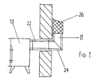
- FIG 1 shows a balanced flue stove 10 having a rear flue assembly 11
- Figure 2 shows a balanced flue stove 12 having a top flue assembly 13.
- Each of the stoves 10, 11 has a housing in the form of a sealed unit so that there is no flow of air from within the room or other space being heated into the interior of the housing or vice versa. Operation of the stove thus does not cause cold air to be drawn into the room or other space being heated and does not create draughts.
- the interior of the stove 10 is divided by a baffle 14 into a front part (in which the burner assembly is located) and a rear part.
- the baffle 14 has a configuration as shown in Figures 11 to 13 and is produced by folding a blank 15 having the configuration shown in Figure 14.
- the baffle 14 includes an upper portion 16 which, when the baffle is fitted within the stove 10, extends vertically, and a lower portion 17 which extends at an inclination of 18° to the vertical.
- the lower portion 17 of the baffle 14 extends downwardly and rearwardly from the upper portion 16.
- the length of the baffle 14 and its location in relation to the base 18 and the rear wall 19 of the stove 10 are such that the distance between the lower edge of the baffle 14 and the base 18 is the same as the distance between the lower edge of the baffle 14 and the rear wall 19.
- the upper portion 16 of the baffle 14 is formed with a generally centrally located circular aperture 20 to which a cylindrical discharge tube 21 is connected so as to provide communication between the part of the interior of the housing of the stove 11 in front of the baffle 14 and the central element 22 of the rear flue assembly 11.
- a burner assembly constructed and arranged to operate as described in Patent Specification No. 2 310 276 is disposed within the housing of the stove 10 at the position indicated generally as 23 in Figure 5.
- the rear flue assembly 11 also includes an outer generally tubular element 24, within which the inner element 22 is contained, with the outer tubular element 24 connected to a collar 25 which provides communication between the outer tubular element 24 and the part of the interior of the housing of the stove 10 to the rear of the internal baffle 14.
- the rear flue assembly 11 terminates in a cowl 26 constructed as shown in Figures 15 to 17.
- the cowl 26 comprises a box-like fitting having a horizontal partition 27 formed with a central circular aperture to which a sleeve 28 is connected so as to provide communication between the inner tubular element 22 of the rear flue assembly 11 and the space within the cowl 26 above the partition 27.
- One side wall of the cowl 26 is solid and fits against the building 29 (as shown in Figure 1), while the other three walls are formed, above the level of the partition 27, with arrays of apertures 30 through which hot combustion products can exit into the atmosphere.
- the three walls of the cowl 26 are also formed with second arrays of apertures 31 which are located below the level of the partition 27.
- the part of the interior of the cowl 26 beneath the partition 27 and surrounding the sleeve 28 is connected to a second sleeve 32 which is connected to the outer tubular element 24 of the rear flue assembly 11. Air from the atmosphere can thus be drawn into the interior of the cowl 26 below the partition 27 through the apertures 31. It will then pass along the outer tubular element 24 into the rear portion of the interior of the stove 10 behind the baffle 14 before flowing under the lower edge of the baffle 14 so as to be available to the burner assembly.
- the hot combustion products from the burner assembly will pass through the inner tubular element 22 for discharge into the atmosphere through the apertures 30 of the cowl 26.
- air for combustion will be drawn into the interior of the stove 10 from the atmosphere through the apertures 31 of the cowl 26. Heat exchange will occur between the hot combustion products and the air for combustion, thereby providing a pre-heating effect.
- a high-efficiency, balanced flue stove is thus provided. Efficient operation of the stove 10 will be obtained as well as efficient heating of the room or other space in which the stove 10 is located.
- An important advantage of the balanced flue stove is that, as the stove is a sealed unit, no air is withdrawn from the room in which the stove is located and no combustion products can enter the room in which the stove is located. This has health and safety advantages and is of particular benefit to sufferers from chest diseases or respiratory infections, e.g. sufferers from bronchitis.
- a further advantage of the stove of the present invention is that it is installation-friendly. No chimney is required and the stove can thus be fitted simply and economically in a room or other location which is to be heated.
- the stove 12 shown in Figure 2 has a top flue assembly 13 which terminates in a cowl 33 constructed as shown in Figures 18 and 19. It contains an internal baffle assembly 34 constructed as shown in Figures 9 and 10 so as to provide communication between the part of the interior of the stove 12 in front of the baffle 34 and the inner tubular element of the top flue assembly 13.
- the construction and mode of operation of the strove 12 will be readily apparent from the drawings and from the detailed description given above of the stove 10.
- FIG 20 shows an arrangement which includes a stove 35 having a lower output that the stoves 10 and 12 described above.
- the housing of the stove 35 contains an internal baffle (not shown) and a burner assembly (also not shown) each constructed and arranged as described above with reference to stoves 10 and 12.
- the stove 35 has a rear flue assembly 36 which includes an outer tubular element 37 and an inner tubular element 38. Air for combustion flows through the outer tubular element 37 into the rear portion of the stove 35 behind the baffle before flowing under the lower edge of the baffle so as to be available to the burner assembly. The hot combustion products from the burner assembly will then pass through the inner tubular element 38 of the rear flue assembly 36 to a cowl 39.
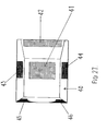
- the cowl 39 is in the form of a box-like housing having an outer cover 40 (see particularly Figure 27) produced as a steel fabrication with parts 41, 42, 43, 44, 45 and 46 constituted by steel gauze so as to allow the free flow of air into the interior of the outer cover 40.
- the outer cover 40 is connected to a combined back plate and shield 47 which, in turn, is connected to the outer tubular element 37 of the rear flue assembly 36.
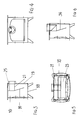
- the cowl 39 also includes an exhaust 48 (see Figures 23 and 24) which is connected to the inner tubular element 38 of the rear flue assembly 36.
- the exhaust 48 includes a first section 49, an intermediate section 50 and an end section 51 to which is attached a plate 52 formed with a plurality of apertures 53 so that, in the assembled condition of the cowl 39, air can flow through the apertures 35 into the space within the cowl 39 around the exhaust 48.
- the combined back plate and shield 47 includes a first portion 54 which forms a sold wall for that side of the cowl 39 adjacent the surface of the wall 55 through which the flue assembly 36 is arranged to pass.
- the combined back plate and shield 47 includes a second portion 56, of cylindrical form, which is attached to the outer tubular element 37 of the flue assembly 36, and a third portion 57 which acts as a wind-shield and is formed with a drainage hole 58.
- the areas of gauze 41 to 46 allow the free flow of air into the space within the cowl 39 around the cowl 48, and thence through the cylindrical portion 56 of the combined backplate and shield 47 into the outer tubular element 37 of the flue assembly 36.
- the portion 57 of the combined backplate and shield 47 ensures that, even in severe gale conditions, the velocity of the air flow through the outer tubular element 37 of the flue assembly 36 will not be such as to "blow out" the flame produced by the burner assembly.
- the flue assembly is arranged so that it passes upwardly through an existing chimney of the room in which it is fitted, rather than passing through a wall.
- the upper end of the flue assembly which will be at about the level of the top of the chimney stack, will then be provided with a suitable cowl permitting the exit of the hot combustion products from the flue assembly and the entry of air for combustion into the flue assembly.
Landscapes
- Engineering & Computer Science (AREA)
- Chemical & Material Sciences (AREA)
- Combustion & Propulsion (AREA)
- Mechanical Engineering (AREA)
- General Engineering & Computer Science (AREA)
- Gas Burners (AREA)
Applications Claiming Priority (2)
| Application Number | Priority Date | Filing Date | Title |
|---|---|---|---|
| GBGB9722631.0A GB9722631D0 (en) | 1997-10-28 | 1997-10-28 | Stoves |
| GB9722631 | 1997-10-28 |
Publications (2)
| Publication Number | Publication Date |
|---|---|
| EP0913647A2 true EP0913647A2 (fr) | 1999-05-06 |
| EP0913647A3 EP0913647A3 (fr) | 2000-03-08 |
Family
ID=10821131
Family Applications (1)
| Application Number | Title | Priority Date | Filing Date |
|---|---|---|---|
| EP98308801A Withdrawn EP0913647A3 (fr) | 1997-10-28 | 1998-10-27 | Fours |
Country Status (2)
| Country | Link |
|---|---|
| EP (1) | EP0913647A3 (fr) |
| GB (2) | GB9722631D0 (fr) |
Family Cites Families (4)
| Publication number | Priority date | Publication date | Assignee | Title |
|---|---|---|---|---|
| GB1076677A (en) * | 1965-06-22 | 1967-07-19 | Empire Stove Company | Gas-fired space heater |
| DE2822185A1 (de) * | 1978-05-20 | 1979-11-22 | Justushuette Zweigwerk Der Fa | Gasheizofen |
| US5020512A (en) * | 1984-08-09 | 1991-06-04 | State Industries, Inc. | Water heater construction and method of heating water |
| US5320086A (en) * | 1993-02-16 | 1994-06-14 | Majco Building Specialties, L.P. | Direct vent gas appliance with vertical and horizontal venting |
-
1997
- 1997-10-28 GB GBGB9722631.0A patent/GB9722631D0/en not_active Ceased
-
1998
- 1998-10-27 EP EP98308801A patent/EP0913647A3/fr not_active Withdrawn
- 1998-10-27 GB GB9823367A patent/GB2330902A/en not_active Withdrawn
Also Published As
| Publication number | Publication date |
|---|---|
| EP0913647A3 (fr) | 2000-03-08 |
| GB9823367D0 (en) | 1998-12-23 |
| GB2330902A (en) | 1999-05-05 |
| GB9722631D0 (en) | 1997-12-24 |
Similar Documents
| Publication | Publication Date | Title |
|---|---|---|
| CA1283010C (fr) | Appareil de chauffage en plein air resistant au souffle du vent | |
| US6053162A (en) | Balanced flue sealed vent terminal assembly | |
| US3428040A (en) | Gas heater | |
| US8156931B2 (en) | Direct vent cap | |
| EP1052461A2 (fr) | Chauffe-eau | |
| CA2077126C (fr) | Chaudiere a condensation a tirage force a haut rendement avec terminaisons de ventilation horizontales | |
| US4068649A (en) | Free standing fireplace stove | |
| US6021775A (en) | Mobile home furnace | |
| CA2350619C (fr) | Adaptateur de hotte de tirage, notamment pour poeles et foyers | |
| US4313562A (en) | Flue heat ventilator | |
| EP0913647A2 (fr) | Fours | |
| US6295981B1 (en) | Fireplace with vertical or horizontal venting | |
| AU747420B2 (en) | Combustion air intake apparatus for fuel-fired, direct vent heating appliance | |
| US5293860A (en) | Standing pilot furnace with vented vestibule | |
| US3211079A (en) | Vent cap for gas heating structure | |
| US4103669A (en) | Fireplace heat exchanger assembly | |
| US20050061310A1 (en) | Direct-vent fireplace configurable for top venting or rear venting | |
| CA2338078A1 (fr) | Admissions d'air pour chauffe-eau au gaz | |
| EP1041342A1 (fr) | Chauffe-eau | |
| US199619A (en) | Improvement in automatic stove-pipe ventilators | |
| USRE37128E1 (en) | Standing pilot furnace with vented vestibule | |
| US2776656A (en) | Down draft eliminator | |
| US4240400A (en) | Space heater | |
| US2191064A (en) | Heating apparatus | |
| US5170773A (en) | Space heating unit for recreational vehicles |
Legal Events
| Date | Code | Title | Description |
|---|---|---|---|
| PUAI | Public reference made under article 153(3) epc to a published international application that has entered the european phase |
Free format text: ORIGINAL CODE: 0009012 |
|
| AK | Designated contracting states |
Kind code of ref document: A2 Designated state(s): AT BE CH CY DE DK ES FI FR GB GR IE IT LI LU MC NL PT SE |
|
| AX | Request for extension of the european patent |
Free format text: AL;LT;LV;MK;RO;SI |
|
| PUAL | Search report despatched |
Free format text: ORIGINAL CODE: 0009013 |
|
| AK | Designated contracting states |
Kind code of ref document: A3 Designated state(s): AT BE CH CY DE DK ES FI FR GB GR IE IT LI LU MC NL PT SE |
|
| AX | Request for extension of the european patent |
Free format text: AL;LT;LV;MK;RO;SI |
|
| RIC1 | Information provided on ipc code assigned before grant |
Free format text: 7F 24C 15/00 A, 7F 24C 3/00 B, 7F 23J 13/02 B, 7F 23L 17/04 B |
|
| AKX | Designation fees paid | ||
| STAA | Information on the status of an ep patent application or granted ep patent |
Free format text: STATUS: THE APPLICATION IS DEEMED TO BE WITHDRAWN |
|
| 18D | Application deemed to be withdrawn |
Effective date: 20000909 |
|
| REG | Reference to a national code |
Ref country code: DE Ref legal event code: 8566 |