EP0913649A2 - Lüftungsrost - Google Patents
Lüftungsrost Download PDFInfo
- Publication number
- EP0913649A2 EP0913649A2 EP98870230A EP98870230A EP0913649A2 EP 0913649 A2 EP0913649 A2 EP 0913649A2 EP 98870230 A EP98870230 A EP 98870230A EP 98870230 A EP98870230 A EP 98870230A EP 0913649 A2 EP0913649 A2 EP 0913649A2
- Authority
- EP
- European Patent Office
- Prior art keywords
- supporting member
- trough
- leg
- fin
- shaped member
- Prior art date
- Legal status (The legal status is an assumption and is not a legal conclusion. Google has not performed a legal analysis and makes no representation as to the accuracy of the status listed.)
- Withdrawn
Links
Images



Classifications
-
- F—MECHANICAL ENGINEERING; LIGHTING; HEATING; WEAPONS; BLASTING
- F24—HEATING; RANGES; VENTILATING
- F24F—AIR-CONDITIONING; AIR-HUMIDIFICATION; VENTILATION; USE OF AIR CURRENTS FOR SCREENING
- F24F13/00—Details common to, or for air-conditioning, air-humidification, ventilation or use of air currents for screening
- F24F13/08—Air-flow control members, e.g. louvres, grilles, flaps or guide plates
- F24F13/082—Grilles, registers or guards
Definitions
- the invention relates to a ventilation grate, which is provided with special supporting members for the fins.
- a ventilation grate with supporting members for the fins is described in NL-A-79 02263.
- the supporting members made from aluminium are attached to a carrier, by inserting two nails of each supporting member in the openings of the carrier.
- the ventilation grate according to the invention is a grate that allows to avoid these disadvantages.
- the ventilation grate comprises at least two elongated trough-shaped members onto which supporting members for fins are mounted, whereby a fin is supported by a supporting member of the first trough-shaped member and by a supporting member of the second trough-shaped member.
- the trough-shaped members are provided with two arms with a wing, whereby the wings are substantially directed to each other and whereby the wings have free ends which are separated from each other.
- the supporting member is made of plastic material and has two slots, whereby the wing of a first arm of a trough-shaped member is inserted in a first slot, while the wing of the second arm of this trough-shaped member is inserted in the second slot, so that the supporting member slides or can slide into the trough-shaped member and so that the pivoting of the supporting member with respect to the trough-shaped member is avoided.
- the supporting member has a part that slides into the trough-shaped member, whereby this part has a bottom and a top surface.
- This part bears a first and a second leg between which a fin partially extends, whereby these legs extend outside the trough-shaped member.
- the top surface of the part of a first supporting member and the first leg of this first supporting member touch the bottom surface of the part of the second supporting member and the second leg of the second supporting member.
- the top surface of the part of the lower supporting member and the first leg of this lower supporting member touch the bottom surface of the part of the upper supporting member and the second leg of this upper supporting member.
- the first leg has a side surface that is directed towards the trough-shaped member and that extends at least partially in the extension of the surface of the slot that is situated outside the trough-shaped member, whereby this side surface at least partially touches the wings of the trough-shaped member.
- the first and second leg of a supporting member am substantially perpendicular and held together by a strengthening plate.
- the first leg bears a piece that is provided with a slot in which an edge of a fin is partially inserted, while the second leg is preferably provided with a clamping system in which a protrusion of a fin is inserted.
- the invention also relates to a supporting member and a fin for a grate, as defined in the claims.
- the grate 1 comprises:
- Each trough-shaped member 6, 7 consists of an aluminium profile that has two opposite channels C1, C2. In the extremities of the first channel C1 are inserted two parts 10, which are screwed onto the profiles 2, 5.
- the second channel C2 is defined between the arms 11, 12 with wings 13, 14.
- the free ends of the wings are directed to each other and separated from each other.
- the supporting member 8A is made from plastic material and has two opposite slots 15, 16, whereby the wing 13 of a first arm 11 of a trough-shaped member is inserted into a first slot 15, while the wing 14 of the second arm 12 of this trough-shaped member is inserted into the second slot 16, so that the supporting member 8A slides or can slide into the trough-shaped member (arrow X) and so that the pivoting of the supporting member 8A with respect to the trough-shaped member is avoided.
- the supporting member has a base part 17 that is situated in the channel C2 and that extends between a bottom surface O1 and atop surface B1.
- the part 17 bears a leg 18 that is situated outside the channel C2 and that with part 17 defines the slots 15 and 16, and a leg 19 which is perdendicular to the leg 18.
- the part 17 is provided with a slot 22 which is directed to the outside with respect to the channel C2.
- the leg 18 is provided with a protrusion 20, which is situated above the top surface B1, and which is directed towards the trough-shaped member 6, 7.
- the upper surface B1 and the leg 17 of the lower supporting member 8B touch respectively the bottom surface O1 and the leg 19 of the upper supporting member 8A.
- the protrusion 20 of the upper supporting member 8A is inserted into the slot 22 of the lower supporting member 8B, so that the supporting members are connected to each other and form a whole.
- the protrusion 20 is pushed into the slot 22 and the two supporting members 8A and 8B are indissolubly connected to each other. This is made clear by the figures 13, 14 and 15.
- the leg 18 has a side surface 23 that is directed towards the channel C2 and that touches the wings 13, 14.
- a plate 25 which is perdendicular to the legs 18 and 19, connects these legs as a strengthening means.
- the leg 18 bears at its free extremity a head 26 with a slot 27, while the leg 19 is provided at its free extremity with a clamping system.
- This clamping system consists of two teeth 28A, 28B between which a substantially cylindrical slot 29 is formed.
- the fin 9A, 9B has a free extremity 30 that is inserted in the slot 27 of the leg 18 of a supporting member.
- the fin 9 also bears an element 31 that intermates with the clamping system 28 of the leg 19 to attach the fin onto the supporting member 8.
- the element 31 consists of an arm 32 which bears a substantially cylindrical or U-shaped head 33. This head 33 is inserted into the slot 29 of the clamping system for attaching the fin.
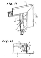
- the two elongated trough-shaped members are parts of two opposite profiles of the frame (see figures 11 and 12).
- the profiles 2, 3, 4, 5 and the trough-shaped members 6, 7 are made from aluminium, while the supporting members 8A, 8B, 8C are made from plastic material (e.g. PVC).
- the profiles, the trough-shaped members and the supporting members are made from plastic material (e.g. PVC).
- Figures 8 through 10 show an advantageous embodiment of a supporting member and of a fin.
- the supporting member 8 is similar to the supporting member that is shown in figure 7, except that the clamping system with teeth 28A, 28B is different. Between the teeth 28A, 28B a substantially cylindrical slot 29 with a recess 40 is formed. This recess 40 is defined between two surfaces V1, V2, between which an angle ⁇ of 30 to 60°, preferably of about 45° is situated. This angle ⁇ is preferably selected such that the point of contact R of the fin on the leg 18 is situated in the plane of the surface V1.
- the fin 9 bears a U-shaped head 33 which is attached onto the arm 32.
- This head 33 consists of an upwards turned wing 33A and a downwards turned wing 33B which is provided with a triangular (in cross section) protrusion 33C.
- This protrusion 33C is intented for insertion into the recess 40.
- the fin 9 comprises a flat upper part 90 that is intended for resting onto the leg 18, a flat lower part 92, and a flat intermediate part 91 that is between the upper part and the lower part.
- the tangent line 93 between the parts 90 and 91 is located in the plane W, in which a surface 33C1 of the protrusion 33C is located.
- a screw 100 can be screwed between the wings 33A, 33B, so that an extra support or attachment of the fin 9 on the supporting member 8 is realised, and/or so that apart from the supporting member 8, also the frame is attached with this screw.
Landscapes
- Engineering & Computer Science (AREA)
- Chemical & Material Sciences (AREA)
- Combustion & Propulsion (AREA)
- Mechanical Engineering (AREA)
- General Engineering & Computer Science (AREA)
- Specific Sealing Or Ventilating Devices For Doors And Windows (AREA)
Applications Claiming Priority (2)
| Application Number | Priority Date | Filing Date | Title |
|---|---|---|---|
| BE9700862A BE1011518A7 (nl) | 1997-10-29 | 1997-10-29 | Rooster. |
| BE9700862 | 1997-10-29 |
Publications (2)
| Publication Number | Publication Date |
|---|---|
| EP0913649A2 true EP0913649A2 (de) | 1999-05-06 |
| EP0913649A3 EP0913649A3 (de) | 2001-09-19 |
Family
ID=3890804
Family Applications (1)
| Application Number | Title | Priority Date | Filing Date |
|---|---|---|---|
| EP98870230A Withdrawn EP0913649A3 (de) | 1997-10-29 | 1998-10-29 | Lüftungsrost |
Country Status (2)
| Country | Link |
|---|---|
| EP (1) | EP0913649A3 (de) |
| BE (1) | BE1011518A7 (de) |
Cited By (3)
| Publication number | Priority date | Publication date | Assignee | Title |
|---|---|---|---|---|
| FR2872889A1 (fr) * | 2004-07-12 | 2006-01-13 | Autogyre Sa | Grille de ventilation destinee a etre installee dans une baie |
| BE1016192A3 (nl) * | 2004-10-19 | 2006-05-02 | Aralco Ventilation Technology | Lamelhouder voor een ventilatierooster en ventilatierooster dat gebruik maakt van zulke lamelhouder. |
| BE1019603A3 (nl) * | 2008-10-16 | 2012-09-04 | Renson Paul | Ventilatie-inrichting. |
Citations (1)
| Publication number | Priority date | Publication date | Assignee | Title |
|---|---|---|---|---|
| NL7902263A (nl) | 1978-03-22 | 1979-09-25 | Greenwood Airvac Ventilation | Ventilatierooster. |
Family Cites Families (5)
| Publication number | Priority date | Publication date | Assignee | Title |
|---|---|---|---|---|
| US2133113A (en) * | 1936-05-21 | 1938-10-11 | H B Dodge And Company | Window blind |
| DE8508631U1 (de) * | 1985-03-22 | 1987-08-06 | Eltreva Ag, Aesch | Befestigung für die Lamellen einer Jalousie |
| GB2242735A (en) * | 1990-04-03 | 1991-10-09 | Tek Group Limited | Louvre ventilators |
| GB9113158D0 (en) * | 1991-06-18 | 1991-08-07 | H H Robertson Uk Limited | Ventilators |
| GB2300473A (en) * | 1995-05-03 | 1996-11-06 | Lbj Profiles Limited | Louvre assembly |
-
1997
- 1997-10-29 BE BE9700862A patent/BE1011518A7/nl not_active IP Right Cessation
-
1998
- 1998-10-29 EP EP98870230A patent/EP0913649A3/de not_active Withdrawn
Patent Citations (1)
| Publication number | Priority date | Publication date | Assignee | Title |
|---|---|---|---|---|
| NL7902263A (nl) | 1978-03-22 | 1979-09-25 | Greenwood Airvac Ventilation | Ventilatierooster. |
Cited By (5)
| Publication number | Priority date | Publication date | Assignee | Title |
|---|---|---|---|---|
| FR2872889A1 (fr) * | 2004-07-12 | 2006-01-13 | Autogyre Sa | Grille de ventilation destinee a etre installee dans une baie |
| EP1617155A1 (de) * | 2004-07-12 | 2006-01-18 | Autogyre | Lüftungsgitter |
| BE1016192A3 (nl) * | 2004-10-19 | 2006-05-02 | Aralco Ventilation Technology | Lamelhouder voor een ventilatierooster en ventilatierooster dat gebruik maakt van zulke lamelhouder. |
| BE1019603A3 (nl) * | 2008-10-16 | 2012-09-04 | Renson Paul | Ventilatie-inrichting. |
| EP2177704A3 (de) * | 2008-10-16 | 2014-01-08 | Renson Ventilation NV | Ventilationsvorrichtung |
Also Published As
| Publication number | Publication date |
|---|---|
| EP0913649A3 (de) | 2001-09-19 |
| BE1011518A7 (nl) | 1999-10-05 |
Similar Documents
| Publication | Publication Date | Title |
|---|---|---|
| ES2219587T3 (es) | Elemento de retencion para molduras de cubierta. | |
| EP0198982B1 (de) | Rasterdecke | |
| US5436798A (en) | Spring clip and heat sink assembly for electronic components | |
| CN100393261C (zh) | 有垂直设置的型材轨和可悬挂在其中的托座的悬挂装置 | |
| CA2502884A1 (en) | Grid muntin retaining clips for muntins | |
| US4532726A (en) | Ticket holders for shelving | |
| US6629616B1 (en) | Stand for bar-shaped or plate-shaped objects | |
| EP0913649A2 (de) | Lüftungsrost | |
| US7243449B2 (en) | Cubicle top nametag display unit | |
| AU746922B2 (en) | Duct lifting lug and method of suspending duct using the lifting lug | |
| EP0584047B1 (de) | Reihe von Elementen zum Gebrauch im belüfteten Fassadenbau | |
| SK21394A3 (en) | Base board heating with a wooden cover | |
| CA2171140A1 (en) | Connector | |
| US7310836B2 (en) | Unit for mounting plumbing fixtures | |
| GB2307544A (en) | Radiator cover | |
| US20030155099A1 (en) | Baseboard heating apparatus | |
| GB2414029A (en) | Cladding elements | |
| EP1656049B1 (de) | System für das abnehmbare aufhängen von regalen | |
| US4878266A (en) | Easel hinge | |
| GB2250910A (en) | Dual wiper extrusion | |
| US20030155100A1 (en) | Baseboard heating apparatus | |
| EP0421975A1 (de) | Heizkörperverkleidung | |
| AU619001B2 (en) | Shelf-support bracket | |
| JPH048839Y2 (de) | ||
| JP4406207B2 (ja) | 間仕切りパネル |
Legal Events
| Date | Code | Title | Description |
|---|---|---|---|
| PUAI | Public reference made under article 153(3) epc to a published international application that has entered the european phase |
Free format text: ORIGINAL CODE: 0009012 |
|
| AK | Designated contracting states |
Kind code of ref document: A2 Designated state(s): AT BE CH CY DE DK ES FI FR GB GR IE IT LI LU MC NL PT SE Kind code of ref document: A2 Designated state(s): AT BE CH CY DE DK ES LI |
|
| AX | Request for extension of the european patent |
Free format text: AL;LT;LV;MK;RO;SI |
|
| PUAL | Search report despatched |
Free format text: ORIGINAL CODE: 0009013 |
|
| AK | Designated contracting states |
Kind code of ref document: A3 Designated state(s): AT BE CH CY DE DK ES FI FR GB GR IE IT LI LU MC NL PT SE |
|
| AX | Request for extension of the european patent |
Free format text: AL;LT;LV;MK;RO;SI |
|
| 17P | Request for examination filed |
Effective date: 20020319 |
|
| AKX | Designation fees paid |
Free format text: AT BE CH CY DE DK ES LI |
|
| RBV | Designated contracting states (corrected) |
Designated state(s): BE DE FR GB IE LU NL |
|
| 17Q | First examination report despatched |
Effective date: 20031112 |
|
| GRAP | Despatch of communication of intention to grant a patent |
Free format text: ORIGINAL CODE: EPIDOSNIGR1 |
|
| STAA | Information on the status of an ep patent application or granted ep patent |
Free format text: STATUS: THE APPLICATION IS DEEMED TO BE WITHDRAWN |
|
| 18D | Application deemed to be withdrawn |
Effective date: 20040915 |