EP0913683A2 - Vorrichtung zur Prüfung nicht-rotationssymmetrischer Hohlkörper auf Defekte - Google Patents
Vorrichtung zur Prüfung nicht-rotationssymmetrischer Hohlkörper auf Defekte Download PDFInfo
- Publication number
- EP0913683A2 EP0913683A2 EP98120234A EP98120234A EP0913683A2 EP 0913683 A2 EP0913683 A2 EP 0913683A2 EP 98120234 A EP98120234 A EP 98120234A EP 98120234 A EP98120234 A EP 98120234A EP 0913683 A2 EP0913683 A2 EP 0913683A2
- Authority
- EP
- European Patent Office
- Prior art keywords
- hollow body
- receiving device
- test area
- hollow
- tested
- Prior art date
- Legal status (The legal status is an assumption and is not a legal conclusion. Google has not performed a legal analysis and makes no representation as to the accuracy of the status listed.)
- Granted
Links
- 230000007547 defect Effects 0.000 title claims abstract description 8
- 238000012360 testing method Methods 0.000 claims abstract description 43
- 238000011156 evaluation Methods 0.000 claims abstract description 6
- 230000001360 synchronised effect Effects 0.000 claims description 13
- 230000001737 promoting effect Effects 0.000 claims description 3
- 239000011521 glass Substances 0.000 description 10
- 230000005540 biological transmission Effects 0.000 description 6
- 230000002950 deficient Effects 0.000 description 4
- 238000005259 measurement Methods 0.000 description 4
- 238000000034 method Methods 0.000 description 4
- 230000008569 process Effects 0.000 description 4
- 210000004127 vitreous body Anatomy 0.000 description 4
- 230000000875 corresponding effect Effects 0.000 description 3
- 230000001419 dependent effect Effects 0.000 description 3
- 230000008901 benefit Effects 0.000 description 2
- 230000003750 conditioning effect Effects 0.000 description 2
- 238000010586 diagram Methods 0.000 description 2
- 230000005484 gravity Effects 0.000 description 2
- 230000007257 malfunction Effects 0.000 description 2
- 230000009471 action Effects 0.000 description 1
- 230000006978 adaptation Effects 0.000 description 1
- 230000008859 change Effects 0.000 description 1
- 238000006243 chemical reaction Methods 0.000 description 1
- 230000001143 conditioned effect Effects 0.000 description 1
- 230000002596 correlated effect Effects 0.000 description 1
- 238000001514 detection method Methods 0.000 description 1
- 229940079593 drug Drugs 0.000 description 1
- 239000003814 drug Substances 0.000 description 1
- 238000004519 manufacturing process Methods 0.000 description 1
- 230000007246 mechanism Effects 0.000 description 1
- 230000003287 optical effect Effects 0.000 description 1
- 239000002304 perfume Substances 0.000 description 1
- 230000004044 response Effects 0.000 description 1
Images



Classifications
-
- G—PHYSICS
- G01—MEASURING; TESTING
- G01N—INVESTIGATING OR ANALYSING MATERIALS BY DETERMINING THEIR CHEMICAL OR PHYSICAL PROPERTIES
- G01N21/00—Investigating or analysing materials by the use of optical means, i.e. using sub-millimetre waves, infrared, visible or ultraviolet light
- G01N21/84—Systems specially adapted for particular applications
- G01N21/88—Investigating the presence of flaws or contamination
- G01N21/90—Investigating the presence of flaws or contamination in a container or its contents
Definitions
- the invention relates to a device for testing non-rotationally symmetrical Hollow body for defects with a feed device for the continuous conveyance of the hollow body in a test area, a funding facility the hollow body through the test area and a facility for transporting the hollow body from the test area.
- the hollow bodies to be tested are preferably around non-rotationally symmetrical glass bodies, e.g. Buckbock bottles, rectangular bottles, triangular bottles, medication bottles or non-rotationally symmetrical perfume bottles.
- non-rotationally symmetrical glass bodies e.g. Buckbock bottles, rectangular bottles, triangular bottles, medication bottles or non-rotationally symmetrical perfume bottles.
- vitreous bodies manufacturing in an automated manner for surface defects, such as. Examine cracks or uneven wall thicknesses and weed out for defective vitreous bodies. It is important in the test process that all sides of the Vitreous can be detected.
- the testing process should as quickly as possible (typically with 1 to 4 bottles per Second). It will also be easy to customize aimed at different vitreous body types.
- the invention has for its object a reliable and flexible test device of the type mentioned create a test using all sides of the hollow body a speed of several hollow bodies per second allowed.
- this object is achieved by that a detector device for recording the nature of the hollow body tested in each case Measured values depending on a hollow body rotation angle and an evaluation device for comparing the recorded ones Measured values with predetermined values for deciding whether the each tested hollow body has defects, provided are, and that the device for promoting the hollow body through the test area designed to enclose the hollow body Recording device with a trained Drive device has that the receiving device over the respective to be tested, from the feeder supplied hollow body is pushed, the Hollow body through the test area on the detector device is transported over that the receiving device in Area of the facility to promote the hollow body from the Test area is removed from the hollow body again, and that the Pick-up device with the hollow body during transport past the detector device by a predetermined Angular amount is rotated.
- the detector device can be, for example act an optically working facility in which the Illuminated vitreous and the degree of reflection or transmission at one or more predetermined heights of the vitreous is measured depending on the angle of rotation.
- Defective vitreous bodies can occur with such a detector device based on a comparison of the angle-dependent reflection or transmission profile of the examined vitreous with saved reflection or transmission profiles intact vitreous can be recognized.
- the receiving device is designed to enclose the hollow body is, the non-rotationally symmetrical hollow body by rotating the recording device around a defined one Angular amount can be rotated, thereby reducing the angle of rotation dependent measurement curve can be recorded.
- the hollow body are defined by the feed device in a Angular position supplied and are rotated by one predetermined angle transported in a defined angular position.
- the receiving device can be easily replaced be designed so that the test device can be quickly adapted to different hollow body contours can.
- the device for promoting the hollow body a Guide holder with one to the axis of rotation of the receiving device centered, moving up and down Guide mandrel, which during transport of the hollow body in Test area from above into an opening (preferably one Bottle neck) of the hollow body to be tested is insertable. So that during the transport and rotation process Avoid falling over the hollow body.
- the receiving device to their Rotation axis rotatably mounted on one of an eccentric device driven first carriage device arranged which is a lifting movement and a transverse to this running transport movement, and that the receiving device has an external toothing with a gear driven by a synchronous motor stands.
- the first rail device makes a continuous Movement of the receiving device on a substantially elliptical orbit.
- the driving eccentric device is preferably mechanical with the usual by means of screw conveyors and Further transport devices synchronized.
- the synchronous motor introduces one in the engagement phase of the receiving device Movement by a predetermined angle and causes a corresponding rotation of the receiving device.
- the the Control known rotor position of the synchronous motor can with correlated with the angular position of the hollow body be, so that an absolute value detection of the current angular position of the hollow body is possible.
- the synchronous motor on one of the lifting movement of the receiving device non-participating element of the first slide device is arranged, and that the rotation of the drive axle of the synchronous motor on the gear via Shaft with a non-rotationally symmetrical cross-section on which the gear wheel slides with a corresponding recess, is transmitted.
- the wave is a multi-tooth spline.
- the receiving device vertically movable on one on the first Carriage device arranged second carriage device is stored by during the proper Test operation the lifting and transport movement of the sled device is transferred to the receiving device, through which, however, when the receiving device strikes one obstacle during the downward movement another Downward movement of the receiving device by a vertical Relative movement between the receiving device and the first carriage device is prevented.
- This will avoid damage to the system and / or the hollow body, if a hollow body is sloping, one falls over the contour of the receiving device has a protruding contour or the like.
- the second track facility continues to offer the advantage of easy adaptation to different To enable bottle types, as shown in the figures will be explained.
- the predetermined angular amount, around the the recording device with the one to be tested Hollow body is rotated, is 540 ° (11 ⁇ 2 turns). This ensures that the hollow body in a comparable (or when testing hollow bodies with mirror symmetry Same contour) transported further in which they were fed. At the same time a complete recording of the transmission or reflection profiles over the entire angular range of the hollow body of 360 ° allows without the angular ranges in the Evaluation would have to be taken into account in which the rotational movement begins or ends what the evaluation the profiles easier.
- test device according to the invention lies in the fact that this is already with reasonable effort existing testing machines can be retrofitted.
- Fig. 1 is a lifting and transport arm 8 with a total with 10 marked receiving arrangement for a testing glass bottle 12 with a rectangular outer contour shown.
- the lifting and transport arm 8 is not a shown eccentric on a substantially elliptical Railway moves.
- the process is as follows:
- the admission order 10 is via the one (not shown) Feed screw fed and on a conveyor belt 18 standing glass bottle 12 lowered.
- the receiving arrangement 10 has a rotatably mounted receiving device 16 which is adapted to the outer contour of the glass bottle 12 in such a way that this can include the bottle.
- Simultaneously with the Receiving arrangement 10 is a guide receptacle 14 with a up and down movable guide pin 15 in the Neck of the glass bottle 12 lowered, which makes the bottle additional can be stabilized.
- the optical transmission profile by a measuring device (not shown) dependent on one or more heights of the glass bottle 12 taken from their rotation angle.
- the rotation takes place so quickly that the continuous onward transport of the Glass bottle 12 does not significantly affect the measurement.
- the Movement of the lifting and transport arm 8 can during the Carrying out the measurement e.g. by a change in the path area the drive mechanism (e.g. flattening of the eccentric) additionally slowed down.
- the guide receptacle 14 or the receptacle arrangement 10 pulled up from the glass bottle 12.
- the glass bottle 12 is then transported away from the test area via the conveyor belt 18, and the lifting and transport arm 8 is in the Returned to the starting position, after which the cycle repeats.
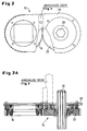
- the receiving arrangement 10 is in one preferred embodiment shown by the in Fig. 1 shown embodiment differs.
- the admission order 10 has a carrier 28 which is rigid with the lower part of the lifting and transport arm 8 is connected.
- the actual receiving device 16 is on the carrier rotatably mounted.
- the receiving device 16 instructs one the respective bottle contour adapted (in the present case rectangular) recess and is easy to replace trained so that a conversion to another type of bottle is possible within a short time.
- the storage of the Receiving device 16 on the carrier 28 takes place via Ring bearing (see Fig. 2A), preferably four-point thin ring bearing.
- the receiving device 16 also has external teeth on, which engages in a gear 22.
- the Gear 22 is also mounted on ring bearings and has a central recess for a multi-tooth spline shaft 26, via which the drive movement of a (not shown) Synchronous motor on the gear 22 and thus on the receiving device 16 is transmitted.
- the synchronous motor is below the receiving arrangement 10 arranged and accepts not part of the lifting movement of the receiving arrangement, but stands over the multi-tooth spline shaft 26 with the receiving arrangement in permanent mechanical connection.
- the reception facility 10 and the gear 22 are preferably made of plastic.
- FIGS. 3 to 5 are different views of the lifting and Transport arrangement 8 shown. This is about a Eccentric arrangement, not shown, both in horizontal (Transport) as well as in the vertical (lifting) direction.
- the guidance takes place along the horizontal axis of movement via a (not shown) slide assembly on which the entire carrier 29 horizontally in accordance with the eccentric movement is moved.
- Guide carriages are on the carrier 29 arranged, in which a pair of rails 30 with a carriage 31 connected to this moved vertically.
- the carriage 31 is on the (not shown) eccentric device articulated.
- FIG. 6 is a highly schematic block diagram the electronic control of a test device according to present invention shown.
- the dialogue with an operator is processed via an industrial standard computer 42.
- the dialog with the operator takes place via a Screen, keyboard and mouse or trackball, all in common are designated by 40.
- the acquisition of the sensor data and the evaluation of whether a defective hollow body is present, on the other hand is not carried out by the computer 42, but via a signal processor 46, because of the fast clock speeds only in this way the required Response times can be achieved.
- the output and input signals of the signal processor 46 are by means of a signal conditioning unit 48 according to requirements of the respective sensors or actuators conditioned.
- the Input and output signals 50 of the signal conditioning unit 48 include the current position of the drive eccentric of the lifting and transport arm 8, signals one or several reflection / transmission sensors, one control signal for the synchronous motor and a signal by which as Defective hollow bodies can be discarded.
Landscapes
- Physics & Mathematics (AREA)
- Health & Medical Sciences (AREA)
- Life Sciences & Earth Sciences (AREA)
- Chemical & Material Sciences (AREA)
- Analytical Chemistry (AREA)
- Biochemistry (AREA)
- General Health & Medical Sciences (AREA)
- General Physics & Mathematics (AREA)
- Immunology (AREA)
- Pathology (AREA)
- Investigating Materials By The Use Of Optical Means Adapted For Particular Applications (AREA)
- Specific Conveyance Elements (AREA)
Abstract
Description
- Fig. 1
- eine schematische Seitenansicht der Prüfvorrichtung gemäß einer ersten Ausführungsform der vorliegenden Erfindung,
- Figuren 2 und 2A
- eine Draufsicht und eine Seitenansicht einer Aufnahmeanordnung gemäß einer bevorzugten Ausführungsform der Erfindung,
- Figuren 3 bis 5
- Ansichten eines Hub- und Transportarmes gemäß der bevorzugten Ausführungsform der Erfindung, und
- Fig. 6
- eine Blockdarstellung der elektronischen Steuerung einer Prüfvorrichtung gemäß der vorliegenden Erfindung.
Claims (7)
- Vorrichtung zur Prüfung nicht-rotationssymmetrischer Hohlkörper auf Defekte, mit einer Zuführeinrichtung zur kontinuierlichen Förderung der Hohlkörper in einen Prüfbereich, einer Einrichtung zur Förderung der Hohlkörper durch den Prüfbereich und einer Einrichtung zum Transport der Hohlkörper aus dem Prüfbereich, dadurch gekennzeichnet, daß eine Detektoreinrichtung zur Aufnahme von die Beschaffenheit des jeweils geprüften Hohlkörpers (12) charakterisierenden Meßwerten abhängig von einem Hohlkörper-Rotationswinkel und eine Auswerteinrichtung zum Vergleich der aufgenommenen Meßwerte mit vorgegebenen Werten zur Entscheidung, ob der jeweils geprüfte Hohlkörper Defekte aufweist, vorgesehen sind, und daß die Einrichtung zur Förderung der Hohlkörper durch den Prüfbereich eine zum Umfassen des Hohlkörpers ausgebildete Aufnahmeeinrichtung (16) mit einer dahingehend ausgebildeten Antriebseinrichtung aufweist, daß die Aufnahmeeinrichtung (16) über den jeweiligen zu prüfenden, aus der Zuführeinrichtung zugeführten Hohlkörper (12) geschoben wird, der Hohlkörper durch den Prüfbereich an der Detektoreinrichtung vorbei transportiert wird, daß die Aufnahmeeinrichtung (16) im Bereich der Einrichtung zur Förderung der Hohlkörper aus dem Prüfbereich wieder vom Hohlkörper entfernt wird, und daß die Aufnahmeeinrichtung mit dem Hohlkörper während des Transports an der Detektoreinrichtung vorbei um einen vorgegebenen Winkelbetrag rotiert wird.
- Vorrichtung nach Anspruch 1, dadurch gekennzeichnet, daß die zum Umfassen der Hohlkörper ausgebildete Aufnahmeeinrichtung (16) leicht auswechselbar ausgebildet ist.
- Vorrichtung nach Anspruch 1 oder 2, dadurch gekennzeichnet, daß die Einrichtung zur Förderung der Hohlkörper eine Führungsaufnahme (14) mit einem zur Rotationsachse der Aufnahmeeinrichtung (16) zentrierten, nach oben- bzw. unten beweglichen Führungsdorn (15) aufweist, der beim Transport des Hohlkörpers (12) im Prüfbereich von oben in eine Öffnung des zu prüfenden Hohlkörpers einführbar ist.
- Vorrichtung nach einem der Ansprüche 1 bis 3, dadurch gekennzeichnet, daß die Aufnahmeeinrichtung (16) um ihre Rotationsachse drehbar gelagert an einer von einer Exzentereinrichtung angetriebenen ersten Schlitteneinrichtung angeordnet ist, die eine Hubbewegung und eine quer zu dieser verlaufende Transportbewegung ausführt, und daß die Aufnahmeeinrichtung (16) eine Außenverzahnung aufweist, die mit einem von einem Synchronmotor angetriebenen Zahnrad (22) in Eingriff steht.
- Vorrichtung nach Anspruch 4, dadurch gekennzeichnet, daß der Synchronmotor an einem an der Hubbewegung der Aufnahmeeinrichtung (16) nicht teilnehmenden Element der ersten Schlitteneinrichtung angeordnet ist, und daß die Rotation der Antriebsachse des Synchronmotors auf das Zahnrad (22) über eine Welle (26) mit nicht-rotationssymmetrischem Querschnitt, auf der das Zahnrad (22) mit einer korrespondierenden Ausnehmung gleitet, übertragen wird.
- Vorrichtung nach Anspruch 5, dadurch gekennzeichnet, daß die Aufnahmeeinrichtung (16) in vertikaler Richtung beweglich auf einer auf der ersten Schlitteneinrichtung angeordneten zweiten Schlitteneinrichtung (32) gelagert ist, durch die während des ordnungsgemäßen Prüfungsbetriebs die Hub- und Transportbewegung der Schlitteneinrichtung auf die Aufnahmeeinrichtung (16) übertragen wird, durch die jedoch bei einem Auftreffen der Aufnahmeeinrichtung (16) auf ein Hindernis während der Abwärtsbewegung eine weitere Abwärtsbewegung der Aufnahmeeinrichtung durch eine vertikale Relativbewegung zwischen der Aufnahmeeinrichtung und der ersten Schlitteneinrichtung verhindert wird.
- Vorrichtung nach einem der Ansprüche 1 bis 6, dadurch gekennzeichnet, daß der vorgegebene Winkelbetrag, um den die Aufnahmeeinrichtung (16) mit dem zu prüfenden Hohlkörper rotiert wird, 540° beträgt.
Applications Claiming Priority (4)
| Application Number | Priority Date | Filing Date | Title |
|---|---|---|---|
| DE29719303U DE29719303U1 (de) | 1997-10-30 | 1997-10-30 | Vorrichtung zur Prüfung nicht-rotationssymmetrischer Hohlkörper auf Defekte |
| DE29719303U | 1997-10-30 | ||
| DE19839746A DE19839746A1 (de) | 1997-10-30 | 1998-09-01 | Vorrichtung zur Prüfung nicht-rotationssymmetrischer Hohlkörper auf Defekte |
| DE19839746 | 1998-09-01 |
Publications (3)
| Publication Number | Publication Date |
|---|---|
| EP0913683A2 true EP0913683A2 (de) | 1999-05-06 |
| EP0913683A3 EP0913683A3 (de) | 1999-09-29 |
| EP0913683B1 EP0913683B1 (de) | 2003-01-29 |
Family
ID=26048511
Family Applications (1)
| Application Number | Title | Priority Date | Filing Date |
|---|---|---|---|
| EP98120234A Expired - Lifetime EP0913683B1 (de) | 1997-10-30 | 1998-10-26 | Vorrichtung zur Prüfung nicht-rotationssymmetrischer Hohlkörper auf Defekte |
Country Status (2)
| Country | Link |
|---|---|
| US (1) | US6237431B1 (de) |
| EP (1) | EP0913683B1 (de) |
Families Citing this family (3)
| Publication number | Priority date | Publication date | Assignee | Title |
|---|---|---|---|---|
| DE10200776A1 (de) * | 2002-01-10 | 2003-07-24 | Zf Lemfoerder Metallwaren Ag | Rissprüfanlage zum Überprüfen von Teilen |
| US20050067333A1 (en) * | 2003-09-29 | 2005-03-31 | Unitech, Inc. | Method and apparatus for detecting a cracked or broken case |
| CN114278826B (zh) * | 2021-12-30 | 2025-01-21 | 武汉创恒激光智能装备有限公司 | 一种垂直升降装置及检测装置 |
Family Cites Families (7)
| Publication number | Priority date | Publication date | Assignee | Title |
|---|---|---|---|---|
| US3944058A (en) * | 1973-04-19 | 1976-03-16 | Indian Head Inc. | Bottle conveyor system including adjustable height continuous belt conveyor and positive lock spray shielded rotatable bottle carrier |
| FR2378276A1 (fr) * | 1977-01-25 | 1978-08-18 | Emballage Ste Gle Pour | Procede et dispositif pour la detection optique de defauts dans des objets transparents, notamment en verre |
| US4323158A (en) * | 1980-07-03 | 1982-04-06 | Wheaton Industries | Bottle neck finish inspection apparatus |
| DE3621976A1 (de) * | 1986-07-01 | 1988-01-07 | Kronseder Maschf Krones | Verfahren und vorrichtung zum pruefen von leeren getraenkeflaschen oder dgl. |
| US4863275A (en) * | 1988-04-20 | 1989-09-05 | Ball Corporation | Portable, shock-proof container surface profiling instrumentation |
| FR2669429B1 (fr) * | 1990-11-20 | 1994-04-15 | Saint Gobain Cinematique Control | Controle optique au vol. |
| JP3351910B2 (ja) * | 1994-09-01 | 2002-12-03 | エーザイ株式会社 | バイアル瓶の検査方法と装置 |
-
1998
- 1998-10-26 EP EP98120234A patent/EP0913683B1/de not_active Expired - Lifetime
- 1998-10-28 US US09/181,347 patent/US6237431B1/en not_active Expired - Fee Related
Also Published As
| Publication number | Publication date |
|---|---|
| US6237431B1 (en) | 2001-05-29 |
| EP0913683A3 (de) | 1999-09-29 |
| EP0913683B1 (de) | 2003-01-29 |
Similar Documents
| Publication | Publication Date | Title |
|---|---|---|
| EP0415154B2 (de) | Verfahren zum Inspizieren von Gegenständen aus unterschiedlichen Blickwinkeln | |
| WO1993006303A1 (de) | Verfahren zur geleisevermessung | |
| EP0615906B1 (de) | Vorrichtung zum Prüfen von Zigaretten | |
| DE102008017427B4 (de) | Vorrichtung sowie Verfahren zur Inspektion von Flaschen oder dergleichen Behältern | |
| DE102011000025A1 (de) | Vorrichtung zum Erfassen von Waren | |
| DE4033585C2 (de) | ||
| EP0349823A1 (de) | Verfahren und Vorrichtung zur Überprüfung von Zigaretten | |
| EP3883868B1 (de) | Teleskopförderer mit integriertem takt- und messfördermittel | |
| DE10102673A1 (de) | Verfahren zur Bestimmung des Raddurchmessers und/oder Radprofils von Schienenfahrzeugrädern | |
| EP0267324A2 (de) | Unwuchtmessstation | |
| DE4128733C2 (de) | Transport- und Bearbeitungseinrichtung für in einem Strom anfallende Stückgüter | |
| DE3607858C2 (de) | ||
| EP0913683B1 (de) | Vorrichtung zur Prüfung nicht-rotationssymmetrischer Hohlkörper auf Defekte | |
| DE69426514T2 (de) | Anordnung zur Kontrolle von Hohlglasbehältern | |
| DE4444787A1 (de) | Vorrichtung zur Vermessung von Werkstücken | |
| DE19831033C2 (de) | Rüstsatzfreie Vorrichtung zum zielgerichteten Bewegen von elektronischen Bauteilen | |
| EP0290877B1 (de) | Vorrichtung zur maschinellen Rücknahme von Leergut | |
| DE3933472C2 (de) | Meßeinrichtung zum Bestimmen der Förderstärke von Massengütern | |
| EP3807195B1 (de) | Vorrichtung zum transportieren von behältern in einer reinigungsmaschine | |
| EP1120341A2 (de) | Verfahren und Vorrichtung zum Bestimmen von Verladeparametern einer Luftfrachtverladeeinheit | |
| DE19839746A1 (de) | Vorrichtung zur Prüfung nicht-rotationssymmetrischer Hohlkörper auf Defekte | |
| EP2290624A1 (de) | Vorrichtung zum Sammeln von Rückgabegebinden und Verfahren zur Gewichtserfassung von Rückgabegebinden | |
| EP1967471A1 (de) | Prüfeinrichtung für ein Transportsystem für Stückgutbehälter | |
| DE4427483C1 (de) | Verfahren und Vorrichtung zum Vermessen von KFZ-Achsen und -Radstellungen | |
| DE4143339A1 (de) | Verfahren zum aufbringen einer codemarkierung auf einer bewegten kunststoffflasche |
Legal Events
| Date | Code | Title | Description |
|---|---|---|---|
| PUAI | Public reference made under article 153(3) epc to a published international application that has entered the european phase |
Free format text: ORIGINAL CODE: 0009012 |
|
| AK | Designated contracting states |
Kind code of ref document: A2 Designated state(s): BE CH DE ES FR GB IT LI NL SE |
|
| AX | Request for extension of the european patent |
Free format text: AL;LT;LV;MK;RO;SI |
|
| PUAL | Search report despatched |
Free format text: ORIGINAL CODE: 0009013 |
|
| AK | Designated contracting states |
Kind code of ref document: A3 Designated state(s): AT BE CH CY DE DK ES FI FR GB GR IE IT LI LU MC NL PT SE |
|
| AX | Request for extension of the european patent |
Free format text: AL;LT;LV;MK;RO;SI |
|
| 17P | Request for examination filed |
Effective date: 19991112 |
|
| AKX | Designation fees paid |
Free format text: BE CH DE ES FR GB IT LI NL SE |
|
| 17Q | First examination report despatched |
Effective date: 20010910 |
|
| RAP1 | Party data changed (applicant data changed or rights of an application transferred) |
Owner name: REINER FRANKE GMBH & CO. GLASBAUTECHNIKMASCHINEN K |
|
| GRAG | Despatch of communication of intention to grant |
Free format text: ORIGINAL CODE: EPIDOS AGRA |
|
| GRAG | Despatch of communication of intention to grant |
Free format text: ORIGINAL CODE: EPIDOS AGRA |
|
| GRAH | Despatch of communication of intention to grant a patent |
Free format text: ORIGINAL CODE: EPIDOS IGRA |
|
| GRAH | Despatch of communication of intention to grant a patent |
Free format text: ORIGINAL CODE: EPIDOS IGRA |
|
| GRAA | (expected) grant |
Free format text: ORIGINAL CODE: 0009210 |
|
| AK | Designated contracting states |
Designated state(s): BE CH DE ES FR GB IT LI NL SE |
|
| PG25 | Lapsed in a contracting state [announced via postgrant information from national office to epo] |
Ref country code: NL Free format text: LAPSE BECAUSE OF FAILURE TO SUBMIT A TRANSLATION OF THE DESCRIPTION OR TO PAY THE FEE WITHIN THE PRESCRIBED TIME-LIMIT Effective date: 20030129 Ref country code: IT Free format text: LAPSE BECAUSE OF FAILURE TO SUBMIT A TRANSLATION OF THE DESCRIPTION OR TO PAY THE FEE WITHIN THE PRE;WARNING: LAPSES OF ITALIAN PATENTS WITH EFFECTIVE DATE BEFORE 2007 MAY HAVE OCCURRED AT ANY TIME BEFORE 2007. THE CORRECT EFFECTIVE DATE MAY BE DIFFERENT FROM THE ONE RECORDED.SCRIBED TIME-LIMIT Effective date: 20030129 Ref country code: GB Free format text: LAPSE BECAUSE OF FAILURE TO SUBMIT A TRANSLATION OF THE DESCRIPTION OR TO PAY THE FEE WITHIN THE PRESCRIBED TIME-LIMIT Effective date: 20030129 |
|
| REG | Reference to a national code |
Ref country code: GB Ref legal event code: FG4D Free format text: NOT ENGLISH |
|
| REG | Reference to a national code |
Ref country code: CH Ref legal event code: EP |
|
| REF | Corresponds to: |
Ref document number: 59807055 Country of ref document: DE Date of ref document: 20030306 Kind code of ref document: P |
|
| PG25 | Lapsed in a contracting state [announced via postgrant information from national office to epo] |
Ref country code: SE Free format text: LAPSE BECAUSE OF FAILURE TO SUBMIT A TRANSLATION OF THE DESCRIPTION OR TO PAY THE FEE WITHIN THE PRESCRIBED TIME-LIMIT Effective date: 20030429 |
|
| NLV1 | Nl: lapsed or annulled due to failure to fulfill the requirements of art. 29p and 29m of the patents act | ||
| GBV | Gb: ep patent (uk) treated as always having been void in accordance with gb section 77(7)/1977 [no translation filed] |
Effective date: 20030129 |
|
| PG25 | Lapsed in a contracting state [announced via postgrant information from national office to epo] |
Ref country code: ES Free format text: LAPSE BECAUSE OF FAILURE TO SUBMIT A TRANSLATION OF THE DESCRIPTION OR TO PAY THE FEE WITHIN THE PRESCRIBED TIME-LIMIT Effective date: 20030730 |
|
| ET | Fr: translation filed | ||
| PGFP | Annual fee paid to national office [announced via postgrant information from national office to epo] |
Ref country code: DE Payment date: 20031021 Year of fee payment: 6 |
|
| PG25 | Lapsed in a contracting state [announced via postgrant information from national office to epo] |
Ref country code: LI Free format text: LAPSE BECAUSE OF NON-PAYMENT OF DUE FEES Effective date: 20031031 Ref country code: CH Free format text: LAPSE BECAUSE OF NON-PAYMENT OF DUE FEES Effective date: 20031031 |
|
| PLBE | No opposition filed within time limit |
Free format text: ORIGINAL CODE: 0009261 |
|
| STAA | Information on the status of an ep patent application or granted ep patent |
Free format text: STATUS: NO OPPOSITION FILED WITHIN TIME LIMIT |
|
| 26N | No opposition filed |
Effective date: 20031030 |
|
| PGFP | Annual fee paid to national office [announced via postgrant information from national office to epo] |
Ref country code: FR Payment date: 20040419 Year of fee payment: 6 |
|
| PGFP | Annual fee paid to national office [announced via postgrant information from national office to epo] |
Ref country code: BE Payment date: 20040603 Year of fee payment: 6 |
|
| REG | Reference to a national code |
Ref country code: CH Ref legal event code: PL |
|
| PG25 | Lapsed in a contracting state [announced via postgrant information from national office to epo] |
Ref country code: BE Free format text: LAPSE BECAUSE OF NON-PAYMENT OF DUE FEES Effective date: 20041031 |
|
| BERE | Be: lapsed |
Owner name: *REINER FRANKE G.M.B.H. & CO. GLASBAUTECHNIKMASCHI Effective date: 20041031 |
|
| PG25 | Lapsed in a contracting state [announced via postgrant information from national office to epo] |
Ref country code: DE Free format text: LAPSE BECAUSE OF NON-PAYMENT OF DUE FEES Effective date: 20050503 |
|
| PG25 | Lapsed in a contracting state [announced via postgrant information from national office to epo] |
Ref country code: FR Free format text: LAPSE BECAUSE OF NON-PAYMENT OF DUE FEES Effective date: 20050630 |
|
| REG | Reference to a national code |
Ref country code: FR Ref legal event code: ST |
|
| BERE | Be: lapsed |
Owner name: *REINER FRANKE G.M.B.H. & CO. GLASBAUTECHNIKMASCHI Effective date: 20041031 |