EP0913792A2 - Pathologieabhängige Betrachtung eines verarbeiteten Zahnröntgenfilmes mit Datenbeglaubigung - Google Patents
Pathologieabhängige Betrachtung eines verarbeiteten Zahnröntgenfilmes mit Datenbeglaubigung Download PDFInfo
- Publication number
- EP0913792A2 EP0913792A2 EP98203485A EP98203485A EP0913792A2 EP 0913792 A2 EP0913792 A2 EP 0913792A2 EP 98203485 A EP98203485 A EP 98203485A EP 98203485 A EP98203485 A EP 98203485A EP 0913792 A2 EP0913792 A2 EP 0913792A2
- Authority
- EP
- European Patent Office
- Prior art keywords
- image
- digital
- images
- dental
- processing
- Prior art date
- Legal status (The legal status is an assumption and is not a legal conclusion. Google has not performed a legal analysis and makes no representation as to the accuracy of the status listed.)
- Granted
Links
Images


Classifications
-
- G—PHYSICS
- G06—COMPUTING OR CALCULATING; COUNTING
- G06T—IMAGE DATA PROCESSING OR GENERATION, IN GENERAL
- G06T5/00—Image enhancement or restoration
- G06T5/90—Dynamic range modification of images or parts thereof
- G06T5/92—Dynamic range modification of images or parts thereof based on global image properties
-
- G—PHYSICS
- G06—COMPUTING OR CALCULATING; COUNTING
- G06T—IMAGE DATA PROCESSING OR GENERATION, IN GENERAL
- G06T5/00—Image enhancement or restoration
- G06T5/40—Image enhancement or restoration using histogram techniques
Definitions
- This invention relates in general to the field of digital data processing and acquisition for imaging systems using flat-bed scanners.
- a primary application of the invention relates to the automatic digitization of small format films, such as dental radiograph films, and to the processing of digital images.
- Film digitization can be a low-cost and practical alternative to digital radiographic approaches such as storage phosphor computed radiography (CR) or direct digital image capture (CCD).
- digital radiographic approaches such as storage phosphor computed radiography (CR) or direct digital image capture (CCD).
- CR storage phosphor computed radiography
- CCD direct digital image capture
- hybrid imaging systems can provide an expedient and low cost solution for both dentists and insurance companies.
- the dental practitioner Without the more significant capital investment required for direct digital devices, the dental practitioner can have the advantages that the digital modality can offer, such as imaging capability to practice management, larger format imagery, and electronic insurance claims. Insurance companies are also motivated to advance to the electronic domain in order to reduce the overhead associated with manual claims submission.
- An important feature for electronic claims containing images is to provide the capability of verifying the authenticity of the digital images.
- Digital images can provide flexibility to the viewer that the film image cannot. Contrast/brightness levels can be changed so that the signal present in the image can be perceived more thoroughly. This capability can be applied to localized regions of the digital image to enhance certain desired regions of interest according to user preference. This can be especially useful when probing areas of a digitized dental film for small signals that may be present in certain anatomical regions, such as interproximal or periapical regions.
- U.S. Patents 5,164,993 and 5,633,511 generally disclose the construction of tone-scale look-up-tables.
- image capture Another important consideration during image capture is the alignment of the radiograph on the platen in the correct horizontal and vertical directions to maintain consistency with the CCD array of the digitizing scanner. If the image is not aligned properly during scaring, image rotation may be required, which can alter the aspect ratio of the original image. To minimize the effects of unwanted flare and image rotation, it is desirable that a template be used that will surround a small film with a dark mask. Alternatively, images can be in a holder typical of the dental practitioner's record keeping.
- U.S. Patent 5,345,513 discloses the method for enhancement is based on histogram analysis of the digitized x-ray film image so that each pixel represents a density value. In particular, this analysis is demonstrated on chest x-rays.
- the histogram has unique regional signatures, each corresponding to anatomical structures, such as heart or lung regions.
- the image is then processed dynamically by constructing a piecewise contrast curve specific to chest x-ray anatomy. This method relies on the characterization of the histogram to provide region specific information for rendering the image, but does not address the problem of digitizing film.
- U.S. Patent 5,283,736 addresses the need for medical diagnosis from a digitized radiographic image providing a means for signal dependent image processing by thresholding relevant image areas to determine key values for each desired image area.
- the image data from desired regions of interest are used to determine a preferred density range, or a tone scale map.
- U.S. Patent 5,172,419 provides a system to correct exposures of x-ray film thus bypassing the need for second exposure so that an image acquisition, storage and display device can be used to improve image density.
- This system includes a film densitometer for digitizing film, storage, image processing and film recorder.
- the digitizer produces a representation of the optical densities for each pixel.
- Reference data (LUT) is stored consisting of optical densities and corresponding exposure for radiographic films.
- the digitized data is compared to the table to determine the exposure of the image and a correction value is calculating and used to modify the pixel data so that the transformed pixels can be mapped for hard copy output (film) yielding the enhanced x-ray image
- European Patent Application 90200969.5 entitled “Processing and Digitizing Apparatus for Medical Radiographic Film,” provides the means for processing and digitizing exposed film, offering a way to automatically digitize conventionally produce radiographs so that patient information is associated with each image for archival purposes.
- U.S. Patent 5,483,325 describes an accessory frame that can be mounted on a photocopier or electronic flatbed scanner that facilitates location and removal of small opaque originals, such as business cards. This patent does not address the problem of flare in copying transparent originals.
- a sensitometric curve can be relied upon to adjust pixel values found in the corresponding digitized radiograph.
- This technique requires more precise knowledge of the exposure levels, film and sensitometry, usually found in larger medical facilities. In the dental community that this work addresses, the wide range in variability of film type used and in film processing would make this technique unfeasible for digitized dental films.
- an image dependent hybrid imaging system for small format films such as dental radiographs.
- the invention has two stages. The first is the scanning of the small format films, such as dental radiographs on a flat-bed scanner. The second is the processing of the digitized images for soft copy display.
- the first stage consists of image dependent capture. There are two components. First is the pre-scanning of the platen area using an image template or any such film holder. Subsequent to the pre-scan is the automatic determination of the image to be scanned by bounding only the image area(s) desired.
- a template containing apertures dimensioned for size 0, 1, 2, 3, or 4 dental films, for example, is placed on the platen and dental radiographs can be placed inside the template apertures. This is done to minimize unwanted flare during scanning.
- the image of the pre-scanned platen is presented to the user on a video display (eg., CRT) and images are selected from the display to be digitized (further). If the exact dimensions and position of the template apertures are known, then the location of the closest open region from the user selection point defines the image area to be scanned.
- the Hough transform can be implemented along with apriori knowledge of the pre-scan image size.
- the scan area of interest can then be determined automatically and each dental radiograph as represented by the pre-scan can be bounded by a rectangle. Exposure levels during scan time are automatically adjusted to provide better image capture conditions on an image by image basis. The desired image area of the platen is scanned twice. A histogram analysis of a smoothed histogram of the initial prescan determines the exposure level to be adjusted for the final scan by analysis of the range of scanner code values found in the image.
- a flat-bed scanner is first calibrated using a step-wedge of density steps.
- a look-up-table is constructed providing the relationship between scanner code values as outputted by the scanner and optical (or diffuse) densities contained in the step-wedge. This can be modeled explicitly where scanner code values are outputted in transmittance and no other non-linearities are introduced into the scanner.
- a look-up-table can be explicitly calculated from this so that in solving for Density the digitized image is represented in terms of optical densities. This calibration is executed and an associated look-up-table is computed for differing exposure levels or dwell time of the scanner. These transmittance/density LUTs will be used to accommodate under-, normal-, and over-exposed dental radiographs as the relationship between optical film densities and transmittance values is a function of exposure.
- the second step consists of processing of the scanned image.
- a logarithmic transform is applied to the image using a generalized D-LogE curve for dental x-ray film in order to analyze the data.
- This allows for a histogram based method of determining the anatomical regions of interest (ROI) so that a tonescale look-up-table can be constructed.
- This tone scale look-up-table can be used for writing the digital image to laser film if so desired.
- a gamma look-up-table can be generated for viewing the tonescaled image in the soft copy venue on a video display. The option of viewing the image locally to accommodate viewing certain anatomical regions by applying an associated look-up table to enhance the local contrast more appropriately is provided.
- the original digital dental x-ray image is further processed to determine original digital authentication data that is unique to the original digital dental x-ray image. This data is associated with the original digital image data.
- a display digital authentication data for the image is determined. The display data is compared with the original data to authenticate that the original image has not been altered.
- the insurance company benefits by not being overbilled for procedures that have not been performed.
- the technique of the invention captures each image input to the system by regulating exposure during scanning and provides for an image dependent processing and verification method for digital radiographs.
- the invention disclosed here has the capability of automatically controlling and adjusting exposures during digitization on the platen of a flat-bed scanner. This is important where the optical densities found on the dental radiograph are close to the dynamic range of the scanner. Increased exposure can increase the signal-to-noise ratio where densities are high.
- the technique of the invention differentially accommodates image capture exposure requirements by reducing flare during the scanning process on a flat-bed scanner, automatically determining a single chosen image from the pre-scanned platen, and subsequently processing the image for rendering on a CRT. It also applies specific information about desired density values associated with various anatomical structures found in the dental radiograph and uses this during the image processing step.
- the invention disclosed herein automatically digitizes small format films, such as dental radiograph(s) using a flat-bed scanner and processes the digital image(s) for rendering on a video display (such as a CRT) on an image-by-image basis.
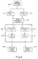
- a high level illustration of the system realizing the invention is depicted in Fig. 1.
- the input to the system is a dental radiograph (or other small format film) (Block 10).
- the output or end result of the invention is a tonescaled version of the input image for display on a CRT (video display). (Block 60).
- This process is conceptualized as a two stage process.
- the first stage consists of the Exposure Control System (Block 20), Image Selection System (Block 30) and Image Capture System (Block 40).
- the Image Capture System generates an intermediate result consisting of a scanned image where a LUT has been downloaded to the scanner (Block 40).
- the second stage is that of Image Dependent Processing (Block 50). Image dependent digitization and processing is
- the Exposure Control System referred to in Fig. 1 is depicted in Figs. 2 and 3.
- the input x-ray image (Block 10 in Fig. 1, represents the same entity as Block 70 in Fig. 2), is the initial input to the system.
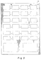
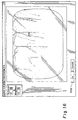
- This input image(s) is placed on the flat-bed scanner platen either inside the apertures of an Exposure Control Template (Fig. 3, Block 90 on Fig. 2) or in any form of dental radiographic holder containing dental radiographs.
- Template 90 includes apertures 92 dimensioned to hold dental radiographs of standard sizes including 0, 1, 2, 3, and 4.
- the regions 94 around apertures 92 are opaque to minimize unwanted flare during scanning.
- the material of template 90 should ideally be black with a matte finish.
- an indicator 96 Located next to each aperture 92 is an indicator 96 to facilitate placement of the dimple marker of dental film in order to properly orient the film in the template. Other indicia may be included to assist in properly orienting the film.
- the intent of using template 90 is to reduce unwanted flare during the process of image capture due to the configuration of a flat-bed scanner with a transparency adapter.
- a second purpose for use of the template is to assist in proper vertical and horizontal alignment of the dental radiograph(s) to the sensor array of the scanner.
- the Exposure Control Template 90 indicates how the radiograph(s) should be placed to eliminate the need to flip or rotate the digitized image. The entire platen is first pre-scanned at a low resolution and is presented on a video display to a user for image(s) selection (Block 100). Subsequent high resolution scanning and processing follow.
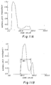
- Fig. 8 shows how extraneous flare has altered the image capture by illustrating the histograms of the same dental radiograph with and without use of the Exposure Control Template.
- the Image Selection System (Block 100, Fig. 1 and Block 140, Fig. 4) is illustrated in Fig. 4.
- the Exposure Control Template (90, Fig. 3)
- the exact locations of all configured rectangles (92, Fig. 3) to hold any radiograph may be known.
- a user-selection point in the interior of a selected radiograph as represented by the pre-scanned platen image is used to locate the closest bounding rectangle of said image. This region of the platen will subsequently be digitized.
- radiographs are placed in a dental holder(s) at the template and then are pre-scanned.
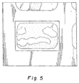
- the Sub-region Bounding System determines a bounding rectangle from a user-selected point in the interior of a selected image on the pre-scanned platen. A sub-region of the displayed pre-scanned platen containing the desired image is selected and processed further. A thresholded gradient image is generated so that the Hough Transform is used to generate an array containing the locations of any vertical and horizontal lines found in this sub-region (Blocks 160, 170). Many methods for doing this are found in Ballard, D.H. and Brown, C.M., Computer Vision, Prentice Hall, 1982, pp.
- Fig. 5 shows the output of this Line Detection System for a selected radiograph contained in a dental holder. This rectangle defines the area of the pre-scanned platen to be digitized at a desired resolution.
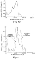
- the Image Capture System (Block 200) independently adjusts exposure levels on an image-by-image basis (Blocks 210, 220) so that the resulting exposure adjustment is used to digitize the said image (Blocks 230, 240). This results in a lower exposure level (typically realized in terms of dwell time), for an under-exposed radiograph and a higher exposure level to digitize an over-exposed radiograph to increase the signal-to-noise ratio for said image. This is realized after the initial pre-scan of the selected image prior to the second, final scan. A histogram analysis of a smoothed histogram is performed on the first scan of the image(s) to determine the range of scanner code values that are significantly associated with structures other than background or amalgam found in the dental radiograph(s).
- Figs. 7A - 7C depict the histograms, respectively, of an under-, normal-, and over-exposed dental radiograph.
- the resulting analysis provides a maximum scanner code value that is associated with anatomical regions and is used to determine whether the dental radiograph(s) is under-, normal-, or over-exposed.
- Exposure level or dwell time is adjusted accordingly.
- These LUTs can be downloaded during scan time to maximize bit selection.
- the radiograph is then digitized and becomes input to the Image Processing System (Block 250, Fig. 4).
- the second stage of the invention is termed an Image Processing System (Block 330, Fig. 6).
- the Density LUT(s) (Block 310, 320) are not downloaded to the scanner, these LUT(s) can be applied in the image processing step prior to the application of the Tone Scale LUT(s).
- the Tone Scale LUT(s) (Blocks 340,350) is computed by analyzing the histogram of the logarithm of the digital values representing densities. This logarithmic function was established by considering a generalized dental x-ray film characteristic curve and is used for the purpose of compressing the data further in order to aid in histogram analysis of a smoothed histogram for finding the regions of anatomical interest (ROI) in the image.
- ROI anatomical interest
- Figs. 11A and 11B illustrate image histograms representing both densities and the logarithm of these densities.
- the shape of these histograms can be uni-, bi-, or tri-modal and depends upon image content. The presence of background and large amounts of amalgam (e.g. bridge work, caps) will yield the tri-modal histogram.
- the first and second derivatives are used in the analysis to search for both peaks and valleys as well as any points of concavity. Endpoints of a region of interest (ROI) is determined to be a percentage of the distance between a peak and a valley where the peak falls below a threshold of the normalized histogram.
- ROI region of interest
- the endpoint is chosen by adding a small percentage of the distance between the point of concavity and the maximum subtracting and/or adding minimum code value in the log image.
- the histogram is uni-modal, the ROI is determined by the range of code values. A small percentage, r, of this range added to the first code value of the image yields the first code value of the ROI. Similarly, ⁇ subtracted from the last code value yields the endpoint of the ROI.
- the first code value of the ROI is determined to represent an anatomical structure of a low density value, such as the enamel area in a bite-wing radiograph.
- the last value of the ROI is determined to be near the threshold between the periodontal bone levels and the background of the radiograph.
- a tonescale curve is constructed (Fig. 6, Blocks 330, 340).
- a piecewise non-linear curve is constructed so that a linear portion extends from the two points determined as the start point and end point of the ROI and such that the first point is mapped to a desired density for enamel areas found in dental images, and the end point of the ROI is mapped to a desired density for the interproximal areas near the background.
- Two non-linear segments are piece-wise constructed representing the "toe" and "shoulder" of the tonescale curve.
- Fig. 6 (Blocks 360, 370) illustrate the CRT LUT(s), which are necessary for display on a CRT display. If the dental images are not displayed, the CRT LUTs are not used.
- the images processed by LUT(s) 340, 350 can be written to film using a laser film writer.
- the inputs are the image(s) outputted from Blocks 340, 350.
- a look-up-table is generated relating to the gamma, ⁇ , of the CRT or other electronic display device.
- the Input Image (Block 20, Fig. 4) is processed to produce the final product output by the invention: a Tonescale Image (Fig. 6, Blocks 380, 390, represents the same entity as Fig. 1, Block 60).
- Figs. 9A and 9B illustrate a processed radiographic Image as outputted by the invention compared to the same radiograph digitized where no default settings have been altered.
- Figs. 10A and 10B illustrate the histograms of these digital images respectively.
- the method of the present invention can be applied a second time to a user selected subregion of the processed image to further adjust the-contrast in the selected region to accommodate pathology dependent viewing of the image.
- a region 400 is selected, for example, by using a standard drawing tool, such as a rectangle or ellipse tool.
- the previously processed pixel values in the selected region are then further processed, as follows, to alter the contrast in that user-selected subregion.
- a histogram 402 is formed of the processed pixels in the selected region. The pixels within the range of the histogram are remapped using a mapping function 404 to produce output code values covering the dynamic range of the CRT (0 - 255).
- the mapping function is implemented as a look-up-table in the image processing system. Any one of several user preferred mapping functions can be applied to specific anatomical areas to provide a appropriate contrast to these local areas.
- the processed pixels in the selected region are replaced by the remapped pixels and the resulting image is displayed.
- An example of the resulting pathology dependent view is shown in Fig. 15.
- Conventional control software for CRT displays include contrast and brightness adjustments.
- a user may prefer a particular contrast and brightness setting to view the images processed as described above.
- a contrast and brightness preference dialog box 406 is provided to the user.
- a software script is generated for automatically applying the selected contrast and brightness to an image. This script is associated with images that are processed in the processing system.
- the preferred contrast and brightness setting is then automatically applied to all images processed by the system before they are displayed. Selecting a particular brightness value has the effect of adding (or subtracting) a constant code value to all of the pixels in the processed image.
- a contrast transform function similar to that shown in Fig. 14 (Block 404).
- a digital authentication data is determined for the original dental radiograph. This data is associated with the original digital dental image.
- digital authentication data is determined for the digital dental image to be displayed. The display authentication data is compared with the original authentication data to authenticate that the original digital dental image has not been altered. If it has the image is labeled as not for diagnostic viewing. If it has not been altered, it is displayed and labeled for diagnostic purposes.
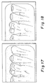
- Fig. 17 shows an unaltered original image while Fig. 18 shows an altered image which includes an added dental filling on the right hand tooth.
- the altered dental image would result in a higher dental fee being paid by the insurer.
- the digital authentication data can take many forms.
- a simple form is a simple determination of the check sum for the entire image.
- a digital dental x-ray image can be a 300 x 200 pixel array with each pixel represented by an 8-bit code value of 0 - 255.
- the check sum would be determined by adding the pixel code values for all 300 x 200 pixels. The determination is simplified since the data from the histogram of the digital dental image can be used.
- Other forms can include using only the region of interest of the digital dental image (such as the upper tooth region, which would include dental fillings), using various algorithms or the like.
Landscapes
- Physics & Mathematics (AREA)
- General Physics & Mathematics (AREA)
- Engineering & Computer Science (AREA)
- Theoretical Computer Science (AREA)
- Apparatus For Radiation Diagnosis (AREA)
- Image Processing (AREA)
- Image Analysis (AREA)
Applications Claiming Priority (4)
| Application Number | Priority Date | Filing Date | Title |
|---|---|---|---|
| US6341697P | 1997-10-28 | 1997-10-28 | |
| US63416P | 1997-10-28 | ||
| US85508 | 1998-05-27 | ||
| US09/085,508 US6195474B1 (en) | 1997-10-28 | 1998-05-27 | Pathology dependent viewing of processed dental radiographic film having authentication data |
Publications (3)
| Publication Number | Publication Date |
|---|---|
| EP0913792A2 true EP0913792A2 (de) | 1999-05-06 |
| EP0913792A3 EP0913792A3 (de) | 1999-12-01 |
| EP0913792B1 EP0913792B1 (de) | 2006-08-16 |
Family
ID=26743404
Family Applications (1)
| Application Number | Title | Priority Date | Filing Date |
|---|---|---|---|
| EP98203485A Expired - Lifetime EP0913792B1 (de) | 1997-10-28 | 1998-10-16 | Pathologieabhängige Betrachtung eines verarbeiteten Zahnröntgenfilmes mit Datenbeglaubigung |
Country Status (4)
| Country | Link |
|---|---|
| US (1) | US6195474B1 (de) |
| EP (1) | EP0913792B1 (de) |
| JP (1) | JPH11213142A (de) |
| DE (1) | DE69835568T2 (de) |
Cited By (2)
| Publication number | Priority date | Publication date | Assignee | Title |
|---|---|---|---|---|
| EP1316919A3 (de) * | 2001-11-14 | 2003-09-10 | Eastman Kodak Company | Methode zur Verbesserung des Kontrasts digitaler Portalbilder |
| US20140259588A1 (en) * | 2013-03-14 | 2014-09-18 | Pcc Structurals, Inc. | Marking template for radiography |
Families Citing this family (17)
| Publication number | Priority date | Publication date | Assignee | Title |
|---|---|---|---|---|
| US6415049B1 (en) * | 1998-04-20 | 2002-07-02 | Konica Corporation | Apparatus for detecting and processing a radiation image |
| US6731756B1 (en) | 1999-06-21 | 2004-05-04 | Elisar Software Corporation, Inc. | Method for securing video images |
| FR2795207B1 (fr) * | 1999-06-21 | 2001-08-17 | Ge Medical Syst Sa | Procede de visualisation d'une partie d'une image tridimensionnelle |
| JP2001136492A (ja) * | 1999-11-09 | 2001-05-18 | Fuji Photo Film Co Ltd | 画像再生装置 |
| US6757442B1 (en) * | 2000-11-22 | 2004-06-29 | Ge Medical Systems Global Technology Company, Llc | Image enhancement method with simultaneous noise reduction, non-uniformity equalization, and contrast enhancement |
| US6934413B2 (en) * | 2001-06-25 | 2005-08-23 | International Business Machines Corporation | Segmentation of text lines in digitized images |
| JP4628608B2 (ja) * | 2001-08-15 | 2011-02-09 | 富士フイルム株式会社 | 異常陰影候補検出装置 |
| US7515314B2 (en) * | 2002-10-28 | 2009-04-07 | Wen-Chao Tseng | Method for correcting negative film images |
| US7245753B2 (en) * | 2003-06-26 | 2007-07-17 | Carestream Health, Inc. | Method for determining dental alignment using radiographs |
| JP4165428B2 (ja) * | 2004-03-30 | 2008-10-15 | セイコーエプソン株式会社 | 画像処理装置、画像処理方法、画像処理を行うコンピュータプログラム、コンピュータプログラムを記録する記録媒体、およびプロジェクタ。 |
| US7113625B2 (en) * | 2004-10-01 | 2006-09-26 | U.S. Pathology Labs, Inc. | System and method for image analysis of slides |
| US7386155B2 (en) * | 2004-11-22 | 2008-06-10 | Carestream Health, Inc. | Transforming visual preference terminology for radiographic images |
| US8150110B2 (en) * | 2006-11-22 | 2012-04-03 | Carestream Health, Inc. | ROI-based rendering for diagnostic image consistency |
| USD702245S1 (en) * | 2012-01-11 | 2014-04-08 | Victor Susman | Scanning frame |
| US20160019680A1 (en) * | 2013-03-29 | 2016-01-21 | Koninklijke Philips N.V. | Image registration |
| US11823376B2 (en) | 2018-05-16 | 2023-11-21 | Benevis Informatics, Llc | Systems and methods for review of computer-aided detection of pathology in images |
| JP2020065193A (ja) * | 2018-10-18 | 2020-04-23 | シャープ株式会社 | 画像形成装置、画像処理方法及び画像処理プログラム |
Family Cites Families (10)
| Publication number | Priority date | Publication date | Assignee | Title |
|---|---|---|---|---|
| EP0452570B1 (de) | 1990-04-19 | 1994-12-28 | Agfa-Gevaert N.V. | Entwicklungs- und Digitalisiermaschine für medizinischen Röntgenfilm |
| US5283736A (en) | 1990-11-29 | 1994-02-01 | Konica Corporation | Radiographic image processing apparatus |
| US5172419A (en) | 1991-03-05 | 1992-12-15 | Lumisys, Inc. | Medical image processing system |
| JPH04303427A (ja) | 1991-03-30 | 1992-10-27 | Fujitsu Ltd | 放射線画像処理方法および放射線画像処理装置 |
| US5164993A (en) | 1991-11-25 | 1992-11-17 | Eastman Kodak Company | Method and apparatus for automatic tonescale generation in digital radiographic images |
| DE69325527T2 (de) * | 1992-02-21 | 1999-11-25 | Canon K.K., Tokio/Tokyo | Gerät und Verfahren zur Bildverarbeitung |
| US5384862A (en) * | 1992-05-29 | 1995-01-24 | Cimpiter Corporation | Radiographic image evaluation apparatus and method |
| US5483325A (en) * | 1994-04-15 | 1996-01-09 | Bodapati; Chandra | Frame for mounting plural sheetlike small originals for simultaneous scanning/copying |
| US5579393A (en) * | 1994-06-21 | 1996-11-26 | Escan, Inc. | System and method for secure medical and dental record interchange |
| US5633511A (en) | 1995-12-22 | 1997-05-27 | Eastman Kodak Company | Automatic tone scale adjustment using image activity measures |
-
1998
- 1998-05-27 US US09/085,508 patent/US6195474B1/en not_active Expired - Fee Related
- 1998-10-16 EP EP98203485A patent/EP0913792B1/de not_active Expired - Lifetime
- 1998-10-16 DE DE69835568T patent/DE69835568T2/de not_active Expired - Fee Related
- 1998-10-23 JP JP10302452A patent/JPH11213142A/ja not_active Withdrawn
Cited By (3)
| Publication number | Priority date | Publication date | Assignee | Title |
|---|---|---|---|---|
| EP1316919A3 (de) * | 2001-11-14 | 2003-09-10 | Eastman Kodak Company | Methode zur Verbesserung des Kontrasts digitaler Portalbilder |
| US20140259588A1 (en) * | 2013-03-14 | 2014-09-18 | Pcc Structurals, Inc. | Marking template for radiography |
| US9275769B2 (en) * | 2013-03-14 | 2016-03-01 | Pcc Structurals, Inc. | Marking template for radiography |
Also Published As
| Publication number | Publication date |
|---|---|
| EP0913792B1 (de) | 2006-08-16 |
| DE69835568T2 (de) | 2007-09-06 |
| JPH11213142A (ja) | 1999-08-06 |
| US6195474B1 (en) | 2001-02-27 |
| DE69835568D1 (de) | 2006-09-28 |
| EP0913792A3 (de) | 1999-12-01 |
Similar Documents
| Publication | Publication Date | Title |
|---|---|---|
| US6292596B1 (en) | Method for automatic image dependent digitization and processing of small format films | |
| US6195474B1 (en) | Pathology dependent viewing of processed dental radiographic film having authentication data | |
| US5384862A (en) | Radiographic image evaluation apparatus and method | |
| US7006688B2 (en) | Histogram adjustment features for use in imaging technologies | |
| EP0599099B1 (de) | Tonkonsistenz in einem Netzwerk für Strahlungsbilder | |
| EP1139284B1 (de) | Verfahren und Gerät zur Durchführung einer lokalen Farbkorrektur | |
| US5447153A (en) | Real-time window/leveling on a radiographic workstation | |
| KR101514519B1 (ko) | 디지털 방사선 영상 관찰을 위한 라이트 박스 효과 | |
| WO1991012540A1 (en) | Tone-scale generation method and apparatus for digital x-ray images | |
| US6249596B1 (en) | Method of locating saturated pixels in the display of a radiographic image | |
| JPH07282248A (ja) | X線画像表示方法および装置 | |
| US20040247197A1 (en) | Correction parameter determining method, correction parameter determining apparatus, computer program, and recording medium | |
| JPH1079023A (ja) | 画像のディジタル表現を発生する方法、画像ディジタル化装置、ならびに画像のディジタル表現および入力プロファイルを編集する方法および装置 | |
| EP0910041A1 (de) | Pathologie-abhängige Beobachtung eines verarbeiteten radiographischen Zahnfilmes | |
| JP2714807B2 (ja) | 放射線画像処理装置 | |
| JP2000013562A (ja) | 小フォ―マットフィルムをデジタル化するためのテンプレ―ト | |
| JP2681482B2 (ja) | 放射線画像処理装置 | |
| JP3455027B2 (ja) | X線画像表示装置 | |
| JP3066919B2 (ja) | 画像処理方法及びこれを用いたシステム | |
| EP0527524B1 (de) | Verfahren zur Qualitätsverbesserung von Bildern | |
| EP0961479A2 (de) | Digitalbildauthentifizierungssystem | |
| WO2025187500A1 (ja) | 骨粗鬆症診断支援のための歯科用パノラマx線画像の視認性向上システム、視認性向上方法、視認性向上プログラム、視認性向上プログラム記憶媒体 | |
| JPH11272851A (ja) | 放射線デジタル画像処理システム | |
| JPH1063831A (ja) | 放射線画像処理方法および装置 | |
| JP2004112650A (ja) | 画像処理方法及び画像表示装置、画像編集装置 |
Legal Events
| Date | Code | Title | Description |
|---|---|---|---|
| PUAI | Public reference made under article 153(3) epc to a published international application that has entered the european phase |
Free format text: ORIGINAL CODE: 0009012 |
|
| AK | Designated contracting states |
Kind code of ref document: A2 Designated state(s): DE FR GB |
|
| AX | Request for extension of the european patent |
Free format text: AL;LT;LV;MK;RO;SI |
|
| PUAL | Search report despatched |
Free format text: ORIGINAL CODE: 0009013 |
|
| AK | Designated contracting states |
Kind code of ref document: A3 Designated state(s): AT BE CH CY DE DK ES FI FR GB GR IE IT LI LU MC NL PT SE |
|
| AX | Request for extension of the european patent |
Free format text: AL;LT;LV;MK;RO;SI |
|
| 17P | Request for examination filed |
Effective date: 20000524 |
|
| AKX | Designation fees paid |
Free format text: DE FR GB |
|
| 17Q | First examination report despatched |
Effective date: 20040109 |
|
| GRAP | Despatch of communication of intention to grant a patent |
Free format text: ORIGINAL CODE: EPIDOSNIGR1 |
|
| GRAS | Grant fee paid |
Free format text: ORIGINAL CODE: EPIDOSNIGR3 |
|
| GRAA | (expected) grant |
Free format text: ORIGINAL CODE: 0009210 |
|
| AK | Designated contracting states |
Kind code of ref document: B1 Designated state(s): DE FR GB |
|
| REG | Reference to a national code |
Ref country code: GB Ref legal event code: FG4D |
|
| REF | Corresponds to: |
Ref document number: 69835568 Country of ref document: DE Date of ref document: 20060928 Kind code of ref document: P |
|
| ET | Fr: translation filed | ||
| PLBE | No opposition filed within time limit |
Free format text: ORIGINAL CODE: 0009261 |
|
| STAA | Information on the status of an ep patent application or granted ep patent |
Free format text: STATUS: NO OPPOSITION FILED WITHIN TIME LIMIT |
|
| 26N | No opposition filed |
Effective date: 20070518 |
|
| PGFP | Annual fee paid to national office [announced via postgrant information from national office to epo] |
Ref country code: GB Payment date: 20070918 Year of fee payment: 10 |
|
| PGFP | Annual fee paid to national office [announced via postgrant information from national office to epo] |
Ref country code: DE Payment date: 20071031 Year of fee payment: 10 |
|
| REG | Reference to a national code |
Ref country code: GB Ref legal event code: 732E |
|
| PGFP | Annual fee paid to national office [announced via postgrant information from national office to epo] |
Ref country code: FR Payment date: 20071004 Year of fee payment: 10 |
|
| REG | Reference to a national code |
Ref country code: FR Ref legal event code: TP |
|
| REG | Reference to a national code |
Ref country code: FR Ref legal event code: TP |
|
| GBPC | Gb: european patent ceased through non-payment of renewal fee |
Effective date: 20081016 |
|
| REG | Reference to a national code |
Ref country code: FR Ref legal event code: ST Effective date: 20090630 |
|
| PG25 | Lapsed in a contracting state [announced via postgrant information from national office to epo] |
Ref country code: DE Free format text: LAPSE BECAUSE OF NON-PAYMENT OF DUE FEES Effective date: 20090501 |
|
| PG25 | Lapsed in a contracting state [announced via postgrant information from national office to epo] |
Ref country code: FR Free format text: LAPSE BECAUSE OF NON-PAYMENT OF DUE FEES Effective date: 20081031 |
|
| PG25 | Lapsed in a contracting state [announced via postgrant information from national office to epo] |
Ref country code: GB Free format text: LAPSE BECAUSE OF NON-PAYMENT OF DUE FEES Effective date: 20081016 |