EP0913794A2 - Méthode de détection d'ombres projetées en mouvement pour la segmentation d'objets - Google Patents
Méthode de détection d'ombres projetées en mouvement pour la segmentation d'objets Download PDFInfo
- Publication number
- EP0913794A2 EP0913794A2 EP98308883A EP98308883A EP0913794A2 EP 0913794 A2 EP0913794 A2 EP 0913794A2 EP 98308883 A EP98308883 A EP 98308883A EP 98308883 A EP98308883 A EP 98308883A EP 0913794 A2 EP0913794 A2 EP 0913794A2
- Authority
- EP
- European Patent Office
- Prior art keywords
- image
- pixel
- moving
- change detection
- cast shadow
- Prior art date
- Legal status (The legal status is an assumption and is not a legal conclusion. Google has not performed a legal analysis and makes no representation as to the accuracy of the status listed.)
- Withdrawn
Links
Images


Classifications
-
- G—PHYSICS
- G06—COMPUTING OR CALCULATING; COUNTING
- G06T—IMAGE DATA PROCESSING OR GENERATION, IN GENERAL
- G06T7/00—Image analysis
- G06T7/20—Analysis of motion
- G06T7/254—Analysis of motion involving subtraction of images
-
- G—PHYSICS
- G06—COMPUTING OR CALCULATING; COUNTING
- G06V—IMAGE OR VIDEO RECOGNITION OR UNDERSTANDING
- G06V10/00—Arrangements for image or video recognition or understanding
- G06V10/20—Image preprocessing
- G06V10/26—Segmentation of patterns in the image field; Cutting or merging of image elements to establish the pattern region, e.g. clustering-based techniques; Detection of occlusion
- G06V10/273—Segmentation of patterns in the image field; Cutting or merging of image elements to establish the pattern region, e.g. clustering-based techniques; Detection of occlusion removing elements interfering with the pattern to be recognised
Definitions
- This known method suffers from shortcomings. Specifically, it cannot distinguish a moving cast shadow from a moving object where the object lacks texture, i.e., lacks sharp contrast within the object.
- An image region changed by a moving cast shadow from a first image to a second image is detected. For each pixel within a change detection mask (a binary mask indicating image areas of difference between the first image and the second image) and a set of neighboring pixels, the following steps are performed. Whether the pixel and the set of neighboring pixels include a static background edge or no edge is determined. Whether the pixel and the set of neighboring pixels include an edge with a spatial signal step width greater than a threshold is determined. Whether the pixel and the set of neighboring pixels have a uniform temporal change of illumination is determined. The pixel is classified as being changed by a moving cast shadow when at least two of the above-mentioned determinations succeed for the pixel or when at least one determination from the above-mentioned determinations succeeds for a majority of the set of neighboring pixels.
- a change detection mask a binary mask indicating image areas of difference between the first image and the second image
- detected image regions are used to estimate the two-dimensional shape of moving objects in image sequences even in the presence of moving cast shadows.
- detected image regions are temporarily integrated to represent the total of moving cast shadows.
- FIG. 2 illustrates a process by which static background edges can be detected, according to an embodiment of the present invention.
- FIG. 3 illustrates a process for testing the spatial constancy of the frame ratio within an image by evaluating its local spatial variance, according to an embodiment of the present invention.
- FIG. 5 illustrates a luminance step model for a luminance step in an image perpendicular to a shadow contour, according to an embodiment of the present invention.
- FIG. 6 illustrates the application of heuristic rules to determine image regions changed by a moving cast shadow, according to an embodiment of the present invention.
- FIGS. 7 and 8 illustrate a process by which two-dimensional shape estimation of moving objects in an image sequence can be applied to image regions changed by moving cast shadows, according to an embodiment of the present invention.
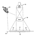
- FIG. 1 shows a possible configuration for the formation of a cast shadow, according to an embodiment of the present invention.
- Object 100 is illuminated by a light source 110.
- Cast shadow 130 is projected onto background 120.
- the cast shadow 130 includes shadow center 131 and shadow penumbras 132.
- Shadow penumbras 132 are soft transitions from dark to bright where some of the light from light source 110 reaches background 120.
- the appearance of cast shadow 130 can be recorded by a video camera 140.
- Cast shadows 130 on background 120 can be detected by the video camera 140 which collects consecutive images and by a processor (not shown) which analyzes the video images.
- the methods described below can be used by the processor to analyze the video images.
- the processor need not be directly coupled to video camera 140; rather, the video images can be detected by the video camera 140 and later analyzed by the processor or the video images can be analyzed in near real time by the processor as each image is being detected by the video camera 140.
- the video images are detected by video camera 140, analyzed by the processor, and sent for transmission over a telecommunications network.
- the appearance of a cast shadow in an image of a video camera 140 can be described by an image signal model.
- the irradiance E k (x,y) is the amount of light power per receiving object surface area.
- Equation 2 the term k(x,y), which has a value between 0 and 1, describes the transition inside penumbra 132 and depends on the scene geometry.
- the intensity c P of the light source is proportional to 1/r 2 with r being the distance between object 100 and light source 110.
- a change detection mask indicates those image regions having a large frame difference between the previous and current image. In other words, the change detection mask indicates the difference in luminance on a per-pixel basis between two consecutive image frames.
- any motion of video camera 140 and background 120 can be restricted.
- the previous image as s k can be motion compensated with respect to the subsequent image s k+1 .
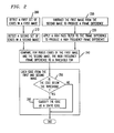
- a first set of edges in a first image is detected.
- a second set of edges in a second image is detected.
- the first image is subtracted from the second image to produce the frame difference.
- a high-frequency filter is applied to the frame difference to produce a high frequency frame difference.
- the high frequency frame difference is compared to a high-frequency threshold.
- the threshold for high-frequency activity can be adaptively calculated from the high frequency activities of the frame difference outside the change detection mask.
- steps 250 and 260 are performed.
- the static edges can be used to detect moving cast shadows on a non-moving background inside the changed detection mask.
- static edges in an image s k (x,y) can be rendered either to the reflectance t(x,y) or to the irradiance E k (x,y).
- Static edges caused by discontinuities in the reflectance suggest a texture in the static background 120.
- Static edges caused by discontinuities in the irradiance suggest discontinuous shading at three-dimensional shape edges of a static background 120.
- static edges inside the change detection mask suggest the possibility of a moving cast shadow 130 on static background 120.
- FIG. 3 illustrates a process for testing the spatial constancy of the frame ratio within an image by evaluating its local spatial variance, according to an embodiment of the present invention.
- Steps 300 through 330 are performed for each pixel for two consecutive frame images.
- the frame ratio is determined for each pixel within the change detection mask.
- the frame ratio is spatially constant in the neighborhood of x, y, because the irradiance is assumed to be constant as discussed above.
- a moving cast shadow can be assumed to position x, y.
- the frame ratio is then tested for spatial constancy by evaluating its local spatial variance.
- the local spatial variance of the frame ratio for the pixel is compared with an illumination threshold.
- a small variance in the local spatial variance should be allowed to address noise compensation.
- conditional step 320 the determination is made as to whether the local spatial variance is below the illumination threshold. If the local spatial variance is below the illumination threshold, then the process proceeds to conditional step 325.
- conditional step 325 a determination is made as to whether the frame ratio in a local neighborhood (e.g., a 3 x 3 pixel area around the pixel being considered) is uniformly above or below one. If this condition is satisfied, then the process proceeds to step 330.
- the pixel is classified as having a uniform temporal change of illumination. The occurrence of a pixel having a uniform temporal change of illumination suggests the presence of a moving cast shadow at that pixel location.
- the illumination threshold can be adaptively calculated from the local variances of the frame ratio outside the change detection mask.
- cast shadow 130 has penumbra regions 132.
- the moving cast shadow 130 can be detected by the existence and characteristics of penumbras 132.
- the penumbra 132 of cast shadow 130 causes a soft luminance step at the contour of a shadow 130.
- the luminance step in an image perpendicular to a shadow contour can be modeled by a luminance step model as illustrated in FIG. 5, according to an embodiment of the present invention.
- the luminance is assumed to rise linearly across shadow penumbra 132 from a low luminance inside a shadow (i.e., center shadow 131) to a high luminance outside the shadow (i.e., background 120).
- the luminance step within penumbra 132 can be characterized by its step height h, step width w and its gradient g which equals h / w . If the width of a luminance step caused by a penumbra 132 is much larger than that of edges caused by the aperture of video camera 140 for surface texture edges of object 100 or edges of object 100, then the luminance step can be used for shadow detection.
- Table 1 characterizes the luminance step height, gradient, and width of different kinds of edges in an image.
- shadow edges can be distinguished from other edges by their luminance step width.
- the luminance step height alone is not an appropriate criterion by which shadow edges can be distinguished because either a shadow edge caused by a bright light source 100 or a texture edge with much contrast may cause a high luminance step.
- the luminance step gradient alone also is not an appropriate criterion by which shadow edges can be distinguished either because the gradient of a shadow edge caused by a bright light source 100 (with a certain extent) may be comparable to that of a texture edge with less contrast (and a small aperture for video camera 140).
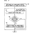
- FIG. 4 illustrates a process by which penumbras can be detected, according to an embodiment of the present invention.
- moving cast shadow border candidates are obtained from the border of the change detection mask.
- the moving cast shadow border candidate can belong to edges of object 100 or a shadow contour, because the change detection mask contains image regions changed by moving objects 100 or moving cast shadows 130.
- the number of moving cast shadow border candidates is low compared to the number of edges indicated by known edge detection algorithms. Moreover, known edge detection algorithms have difficulties in finding soft shadow contours. Additionally, the number of moving cast shadow border candidates is further reduced because the object mask of the first image, if available, is or-connected to the change detection mask to fill holes inside the change detection mask. Also, to enhance the precision, the moving cast shadow border candidates are moved perpendicular to the border of the change detection mask to a position of highest luminance gradient. The gradient is measured perpendicular to the border of the change detection mask using a Sobel operator. The Sobel operator consists of two finite-duration impulse response (FIR) filters with the filter
- Steps 410, 420 and 430 are performed for each moving cast shadow border candidate.
- a spatial signal step width of the frame difference is evaluated.
- the spatial signal step width is compared to a width threshold. If the spatial signal step width exceeds the width threshold, then the moving cast shadow border candidate is classified as a moving cast shadow border in step 430.
- the height and gradient of the signal steps perpendicular to the edge are measured for each moving cast shadow border candidate.
- the signal step height and gradient are measured in the frame difference between two consecutive images because whether the relevant edges are in the previous or in the current image depends on the unknown motion of cast shadows and objects.
- the signal step height can be measured by the difference of the average frame differences from both sides of the edge. For example, a 3 pixel by 3 pixel averaging window (for example, for the common intermediate format (CIF) image format) can be placed beside the edge.
- the signal gradient can be measured using a Sobel operator aligned perpendicular to the edge.
- the direction of the edge can be measured by a regression line evaluating moving cast shadow border candidates in a neighborhood of a 7 pixel by 7 pixel area.
- the spatial signal step width, w equals the height, h, divided by the gradient, g.
- the width threshold can be selected for the particular system as appropriate. For example, the width threshold can equal 2.4 pixels for a standard video camera. The width threshold can be lower for high definition television (HDTV) or higher for low light level video systems.
- HDTV high definition television
- the results of the three criteria from sections 1, 2 and 3 can be evaluated by heuristic rules. For each pixel of the change detection mask, a determination must be made whether the changes are caused by a moving cast shadow or by some other phenomena.
- Table 2 summarizes some of the heuristic evaluation rules to determine whether or not the pixel has been changed by a moving cast shadow. As the table illustrates, the first column considers whether a change was detected. The second column evaluates the result of edge classification from section 1. The third column indicates the result of illumination change classification from section 2 and the fourth column indicates the decision as to whether the pixel has been changed by a moving cast shadow. Additionally, the penumbra criteria from section 3 is evaluated in a local neighborhood of each pixel.
- FIG. 6 illustrates the application of heuristic rules to determine image regions changed by a moving cast shadow, according to an embodiment of the present invention. Steps 600 through 650 are repeated for each pixel within the change detection mask.
- step 600 a determination is made as to whether the pixel and the neighboring pixels include a static background edge. The determination performed in step 600 is made in accordance with the process described in section 1 above.
- step 610 a determination is made as to whether the pixel and the neighboring pixels are close to an edge with a spatial signal step width greater than a width threshold.
- the determination of step 610 can be made according to the process described in section 2 above.
- step 620 a determination is made as to whether the pixel and the neighboring pixels have a uniform temporal change of illumination.
- the determination made in step 620 can be performed according to the process described in section 3 above.
- Steps 630 through 650 classify pixels as being changed by moving cast shadows according to the heuristic rules discussed in Table 2 and Section 3.
- the determinations made in step 600, 610 and 620 are evaluated with respect to the pixel and its neighboring pixels. If, however, at least two determinations for the pixel and its neighboring pixels do not succeed, then the process ends for that pixel. If at least two determinations succeed for the pixel and its neighboring pixel, then the process proceeds to step 650.
- the pixel is classified as being changed by a moving cast shadow.
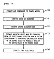
- FIGS. 7 and 8 illustrate a process by which a two-dimensional shape estimation of moving objects in an image sequence can be applied to image sequences containing both moving objects and moving cast shadows according to an embodiment of the present invention.
- the apparent motion of video camera 140 or background 120 can be estimated and compensated to reflect any kind of global motion, e.g., caused by zoom and pan of the camera 140.
- scene cut detection is performed by evaluating whether the mean square error between a current original frame s k+1 and a camera motion compensated from the previous frame s k, CMC exceeds a given threshold. If the threshold is exceeded, then all parameters are reset to their initial values.
- the scene cut detection performed in step 710 is only performed in the background regions of the previous frame which are taken from the previous object mask (OM k ). In that mask, all pixels are set to foreground which belong to a moving object in the previous frame.
- OM k previous object mask
- step 720 a change detection mask between two successive frames is estimated. This step 720 is described in further detail with reference to Fig. 8 and will be discussed below.
- an initial object mask OM' is calculated by eliminating the uncovered background areas from the final change detection mask CDM k+1 . Therefore, displacement information for pixels within the changed regions is used.
- the displacement is estimated by a hierarchical blockmatcher (HBM). See M. Bierling, "Displacement estimation by hierarchical block matching", 3rd SPIE Symposium on Visual Communications and Image Processing, Cambridge, USA, pp. 941-51, November 1988, which is incorporated herein by reference for background.
- the change detection mask from the first step is considered by the HBM. Uncovered background is detected by pixels with foot- or top-point of the corresponding displacement vector being outside the changed area in the final change detection mask, CDM k+1 .
- the final object mask is estimated.
- the boundaries of the initial object mask, OM i are adapted to luminance edges in the current image to improve the accuracy.
- the final result is the final object mask OM k+1 .
- FIG. 8 describes the process by which the change detection mask is estimated in step 720 of FIG. 7, according to an embodiment of the present invention.
- an initial change detection mask, CDM i is determined based on a first image and a second image.
- an initial change detection mask, CDM i between the two successive frames is generated by thresholding the frame difference using a global threshold.
- this initial change detection mask pixels with image luminance change due to a moving object are labeled as changed, others are labeled as unchanged.
- a shadow portion of the change detection mask changed by the moving cast shadow is detected to produce a remaining portion of the change detection mask.
- the process of detecting the shadow portion of a change detection mask which is changed by the moving cast shadow can be done according to the processes described above with reference to sections 1, 2 and 3.
- boundaries of the changed image areas within the remaining portion of the change detection mask are smoothed. These boundaries can be smoothed, for example, by a relaxation technique using locally adapted thresholds. Consequently, the process adapts framewise automatically to noise from video camera 140.
- the smoothed remaining portion of the change detection mask is combined with an object mask from a first image, if available, to produce an object change detection mask.
- This step allows the production of temporally stable object regions.
- the object change detection mask contains all pixels from the remaining portion of a change detection mask which are labeled as changed, and additionally, all pixels which belong to the object mask of the previous frame. This is based on the assumption that all pixels which belong to the previous object mask should belong to the current object change detection mask.
- a pixel from the previous object mask is only labeled as changed in the object change detection mask if it was also labeled as changed in the remaining portion of the change detection mask of one of the last N frames.
- the value N corresponds to the time period which this particular pixel has been identified as being changed.
- the value N adapts automatically to the sequence by evaluating the size and motion amplitudes of the moving objects in the previous frame.
- step 840 small regions from the object change detection mask are eliminated resolving in the final change detection mask CDM k+1 .
Landscapes
- Engineering & Computer Science (AREA)
- Multimedia (AREA)
- Physics & Mathematics (AREA)
- General Physics & Mathematics (AREA)
- Theoretical Computer Science (AREA)
- Computer Vision & Pattern Recognition (AREA)
- Image Analysis (AREA)
Applications Claiming Priority (4)
| Application Number | Priority Date | Filing Date | Title |
|---|---|---|---|
| US6410797P | 1997-11-03 | 1997-11-03 | |
| US64107P | 1997-11-03 | ||
| US177686 | 1998-10-22 | ||
| US09/177,686 US6349113B1 (en) | 1997-11-03 | 1998-10-22 | Method for detecting moving cast shadows object segmentation |
Publications (2)
| Publication Number | Publication Date |
|---|---|
| EP0913794A2 true EP0913794A2 (fr) | 1999-05-06 |
| EP0913794A3 EP0913794A3 (fr) | 2000-12-06 |
Family
ID=26744156
Family Applications (1)
| Application Number | Title | Priority Date | Filing Date |
|---|---|---|---|
| EP98308883A Withdrawn EP0913794A3 (fr) | 1997-11-03 | 1998-10-29 | Méthode de détection d'ombres projetées en mouvement pour la segmentation d'objets |
Country Status (2)
| Country | Link |
|---|---|
| US (1) | US6349113B1 (fr) |
| EP (1) | EP0913794A3 (fr) |
Cited By (5)
| Publication number | Priority date | Publication date | Assignee | Title |
|---|---|---|---|---|
| EP1367554A1 (fr) | 2002-05-30 | 2003-12-03 | Siemens Corporate Research, Inc. | Détection d'objet pour changement soudain d'illumination utilisant une cohérence d'ordre |
| CN103632340A (zh) * | 2012-08-24 | 2014-03-12 | 原相科技股份有限公司 | 物体追踪装置及其操作方法 |
| CN103455998B (zh) * | 2012-06-04 | 2017-12-22 | 中兴通讯股份有限公司 | 视频图像中阴影的检测方法及装置 |
| EP3495995A1 (fr) * | 2017-12-06 | 2019-06-12 | Toshiba Elevator Kabushiki Kaisha | Système de détection d'images |
| WO2019113270A1 (fr) * | 2017-12-06 | 2019-06-13 | Illinois Tool Works Inc. | Procédé d'augmentation de zone de détection d'un système de détection d'intrusion vidéo à base d'ombre |
Families Citing this family (33)
| Publication number | Priority date | Publication date | Assignee | Title |
|---|---|---|---|---|
| KR100716319B1 (ko) * | 1998-09-29 | 2007-05-11 | 지멘스 악티엔게젤샤프트 | 이미지 포인트들을 가진 디지털 이미지를 처리하는 방법 및 장치 |
| US6539055B1 (en) * | 1999-12-03 | 2003-03-25 | Intel Corporation | Scene change detector for video data |
| US7106898B2 (en) * | 1999-12-06 | 2006-09-12 | California Institute Of Technology | 3D scanning using shadows |
| JP3603737B2 (ja) * | 2000-03-30 | 2004-12-22 | 日本電気株式会社 | 移動体追尾方法及びその装置 |
| US9892606B2 (en) | 2001-11-15 | 2018-02-13 | Avigilon Fortress Corporation | Video surveillance system employing video primitives |
| US8564661B2 (en) | 2000-10-24 | 2013-10-22 | Objectvideo, Inc. | Video analytic rule detection system and method |
| US20050162515A1 (en) * | 2000-10-24 | 2005-07-28 | Objectvideo, Inc. | Video surveillance system |
| US8711217B2 (en) * | 2000-10-24 | 2014-04-29 | Objectvideo, Inc. | Video surveillance system employing video primitives |
| US8457401B2 (en) * | 2001-03-23 | 2013-06-04 | Objectvideo, Inc. | Video segmentation using statistical pixel modeling |
| US7424175B2 (en) | 2001-03-23 | 2008-09-09 | Objectvideo, Inc. | Video segmentation using statistical pixel modeling |
| US6625310B2 (en) * | 2001-03-23 | 2003-09-23 | Diamondback Vision, Inc. | Video segmentation using statistical pixel modeling |
| US6845178B1 (en) * | 2001-06-27 | 2005-01-18 | Electro Scientific Industries, Inc. | Automatic separation of subject pixels using segmentation based on multiple planes of measurement data |
| KR100443678B1 (ko) * | 2001-09-29 | 2004-08-09 | 엘지전자 주식회사 | 영상내의 오브젝트 영역 추출방법 |
| US6904159B2 (en) * | 2001-12-20 | 2005-06-07 | Mitsubishi Electric Research Laboratories, Inc. | Identifying moving objects in a video using volume growing and change detection masks |
| US7366323B1 (en) * | 2004-02-19 | 2008-04-29 | Research Foundation Of State University Of New York | Hierarchical static shadow detection method |
| JP4783795B2 (ja) * | 2005-01-27 | 2011-09-28 | タンデント ビジョン サイエンス インコーポレーティッド | 照明および反射境界の区別 |
| US7571638B1 (en) * | 2005-05-10 | 2009-08-11 | Kley Victor B | Tool tips with scanning probe microscopy and/or atomic force microscopy applications |
| US9423693B1 (en) | 2005-05-10 | 2016-08-23 | Victor B. Kley | In-plane scanning probe microscopy tips and tools for wafers and substrates with diverse designs on one wafer or substrate |
| US7423645B2 (en) * | 2005-06-01 | 2008-09-09 | Microsoft Corporation | System for softening images in screen space |
| US7639878B2 (en) * | 2005-11-17 | 2009-12-29 | Honeywell International Inc. | Shadow detection in images |
| US8045761B2 (en) * | 2006-05-30 | 2011-10-25 | Intelliview Technologies Inc. | Detection of environmental conditions in a sequence of images |
| US7784107B2 (en) * | 2006-06-02 | 2010-08-24 | Victor B. Kley | High speed measurement, analysis and imaging systems and methods for length scales from meter to sub-nanometer |
| US8159499B2 (en) * | 2007-08-02 | 2012-04-17 | Disney Enterprises, Inc. | Rendering of shadows with hand-painted appearance |
| JP2009098925A (ja) * | 2007-10-17 | 2009-05-07 | Sony Corp | 画像処理装置、画像処理方法、および、プログラム |
| US8306261B2 (en) * | 2008-06-13 | 2012-11-06 | International Business Machines Corporation | Detection of an object in an image |
| IL196161A (en) * | 2008-12-24 | 2015-03-31 | Rafael Advanced Defense Sys | Download shadows from images within a video signal |
| US8577170B2 (en) * | 2011-09-15 | 2013-11-05 | Microsoft Corporation | Shadow detection in a single image |
| US9778572B1 (en) | 2013-03-15 | 2017-10-03 | Victor B. Kley | In-plane scanning probe microscopy tips and tools for wafers and substrates with diverse designs on one wafer or substrate |
| KR102161052B1 (ko) * | 2013-08-27 | 2020-09-29 | 삼성전자주식회사 | 영상에서 객체를 분리하는 방법 및 장치. |
| US10121254B2 (en) | 2013-08-29 | 2018-11-06 | Disney Enterprises, Inc. | Methods and systems of detecting object boundaries |
| US9710934B1 (en) * | 2015-12-29 | 2017-07-18 | Sony Corporation | Apparatus and method for shadow generation of embedded objects |
| US11436839B2 (en) * | 2018-11-02 | 2022-09-06 | Toyota Research Institute, Inc. | Systems and methods of detecting moving obstacles |
| DE102021210356B4 (de) * | 2021-09-17 | 2024-05-16 | Siemens Healthineers Ag | Verfahren und Einrichtung zur Segmentierung von Hochkontrastobjekten in Röntgenbildern |
Family Cites Families (8)
| Publication number | Priority date | Publication date | Assignee | Title |
|---|---|---|---|---|
| EP0531904A3 (en) | 1991-09-10 | 1993-10-06 | Eastman Kodak Company | Method and apparatus for spatially variant filtering |
| JP3679426B2 (ja) * | 1993-03-15 | 2005-08-03 | マサチューセッツ・インスティチュート・オブ・テクノロジー | 画像データを符号化して夫々がコヒーレントな動きの領域を表わす複数の層とそれら層に付随する動きパラメータとにするシステム |
| US5631976A (en) * | 1994-04-29 | 1997-05-20 | International Business Machines Corporation | Object imaging system |
| IL114838A0 (en) * | 1995-08-04 | 1996-11-14 | Spiegel Ehud | Apparatus and method for object tracking |
| US6026183A (en) * | 1995-10-27 | 2000-02-15 | Texas Instruments Incorporated | Content-based video compression |
| DE19601005A1 (de) * | 1996-01-15 | 1997-07-17 | Bosch Gmbh Robert | Verfahren zur Erkennung bewegter Objekte in zeitlich aufeinanderfolgenden Bildern |
| US6075875A (en) * | 1996-09-30 | 2000-06-13 | Microsoft Corporation | Segmentation of image features using hierarchical analysis of multi-valued image data and weighted averaging of segmentation results |
| US5832115A (en) * | 1997-01-02 | 1998-11-03 | Lucent Technologies Inc. | Ternary image templates for improved semantic compression |
-
1998
- 1998-10-22 US US09/177,686 patent/US6349113B1/en not_active Expired - Lifetime
- 1998-10-29 EP EP98308883A patent/EP0913794A3/fr not_active Withdrawn
Cited By (8)
| Publication number | Priority date | Publication date | Assignee | Title |
|---|---|---|---|---|
| EP1367554A1 (fr) | 2002-05-30 | 2003-12-03 | Siemens Corporate Research, Inc. | Détection d'objet pour changement soudain d'illumination utilisant une cohérence d'ordre |
| CN103455998B (zh) * | 2012-06-04 | 2017-12-22 | 中兴通讯股份有限公司 | 视频图像中阴影的检测方法及装置 |
| CN103632340A (zh) * | 2012-08-24 | 2014-03-12 | 原相科技股份有限公司 | 物体追踪装置及其操作方法 |
| EP3495995A1 (fr) * | 2017-12-06 | 2019-06-12 | Toshiba Elevator Kabushiki Kaisha | Système de détection d'images |
| WO2019113270A1 (fr) * | 2017-12-06 | 2019-06-13 | Illinois Tool Works Inc. | Procédé d'augmentation de zone de détection d'un système de détection d'intrusion vidéo à base d'ombre |
| US10650646B2 (en) | 2017-12-06 | 2020-05-12 | Illinois Tool Works Inc. | Method of increasing detection zone of a shadow-based video intrusion detection system |
| CN111727435A (zh) * | 2017-12-06 | 2020-09-29 | 伊利诺斯工具制品有限公司 | 增大基于阴影的视频入侵检测系统的检测区域的方法 |
| CN111727435B (zh) * | 2017-12-06 | 2024-04-26 | 伊利诺斯工具制品有限公司 | 增大基于阴影的视频入侵检测系统的检测区域的方法 |
Also Published As
| Publication number | Publication date |
|---|---|
| US6349113B1 (en) | 2002-02-19 |
| EP0913794A3 (fr) | 2000-12-06 |
Similar Documents
| Publication | Publication Date | Title |
|---|---|---|
| US6349113B1 (en) | Method for detecting moving cast shadows object segmentation | |
| JP3862140B2 (ja) | ピクセル化されたイメージをセグメント化する方法および装置、並びに記録媒体、プログラム、イメージキャプチャデバイス | |
| Zhang et al. | Fast haze removal for nighttime image using maximum reflectance prior | |
| US9792676B2 (en) | System for background subtraction with 3D camera | |
| US7418134B2 (en) | Method and apparatus for foreground segmentation of video sequences | |
| EP1367554B1 (fr) | Détection d'objet pour changement soudain d'illumination utilisant une cohérence d'ordre | |
| US6661918B1 (en) | Background estimation and segmentation based on range and color | |
| Toth et al. | Illumination-invariant change detection | |
| JP4668921B2 (ja) | 画像中のオブジェクト検出 | |
| EP0648360B1 (fr) | Pourssuite d'objets dans des sequences video | |
| US9258531B2 (en) | System and method for video-quality enhancement | |
| US8280106B2 (en) | Shadow and highlight detection system and method of the same in surveillance camera and recording medium thereof | |
| US7639878B2 (en) | Shadow detection in images | |
| EP1039757A2 (fr) | Video segmentation hiérarchique se basant sur les caractéristiques | |
| US8416993B2 (en) | Object boundary accurate motion detection using hierarchical block splitting and motion segmentation | |
| CN107404628B (zh) | 图像处理装置及方法以及监视系统 | |
| US8837857B2 (en) | Enhancing image data | |
| JPH07302328A (ja) | 背景差分による動物体領域抽出方法 | |
| US6701026B1 (en) | Method and apparatus for cancelling lighting variations in object recognition | |
| Ianasi et al. | A fast algorithm for background tracking in video surveillance, using nonparametric kernel density estimation | |
| EP2178289B1 (fr) | Procédé et unité de détection de mouvement basée sur un histogramme de différence | |
| CN114359209B (zh) | 图像处理方法及装置、存储介质、电子装置 | |
| MXPA98009084A (es) | Metodo para detectar sombras proyectadas moviles para segmentacion de objetos. | |
| Costantini et al. | Countering illumination variations in a video surveillance environment | |
| Kunvar et al. | Real time application to generate the differential time lapse video with edge detection |
Legal Events
| Date | Code | Title | Description |
|---|---|---|---|
| PUAI | Public reference made under article 153(3) epc to a published international application that has entered the european phase |
Free format text: ORIGINAL CODE: 0009012 |
|
| AK | Designated contracting states |
Kind code of ref document: A2 Designated state(s): DE FI FR GB |
|
| AX | Request for extension of the european patent |
Free format text: AL;LT;LV;MK;RO;SI |
|
| PUAL | Search report despatched |
Free format text: ORIGINAL CODE: 0009013 |
|
| AK | Designated contracting states |
Kind code of ref document: A3 Designated state(s): AT BE CH CY DE DK ES FI FR GB GR IE IT LI LU MC NL PT SE |
|
| AX | Request for extension of the european patent |
Free format text: AL;LT;LV;MK;RO;SI |
|
| 17P | Request for examination filed |
Effective date: 20010509 |
|
| AKX | Designation fees paid |
Free format text: DE FI FR GB |
|
| 17Q | First examination report despatched |
Effective date: 20071005 |
|
| STAA | Information on the status of an ep patent application or granted ep patent |
Free format text: STATUS: THE APPLICATION IS DEEMED TO BE WITHDRAWN |
|
| 18D | Application deemed to be withdrawn |
Effective date: 20120823 |