EP0913855A2 - Kurzbogenlampe - Google Patents
Kurzbogenlampe Download PDFInfo
- Publication number
- EP0913855A2 EP0913855A2 EP98120496A EP98120496A EP0913855A2 EP 0913855 A2 EP0913855 A2 EP 0913855A2 EP 98120496 A EP98120496 A EP 98120496A EP 98120496 A EP98120496 A EP 98120496A EP 0913855 A2 EP0913855 A2 EP 0913855A2
- Authority
- EP
- European Patent Office
- Prior art keywords
- cylindrical retaining
- short arc
- arc lamp
- shrunken
- retaining bodies
- Prior art date
- Legal status (The legal status is an assumption and is not a legal conclusion. Google has not performed a legal analysis and makes no representation as to the accuracy of the status listed.)
- Granted
Links
- 239000000919 ceramic Substances 0.000 claims abstract description 12
- 229910052751 metal Inorganic materials 0.000 claims abstract description 7
- 239000002184 metal Substances 0.000 claims abstract description 7
- ZOKXTWBITQBERF-UHFFFAOYSA-N Molybdenum Chemical group [Mo] ZOKXTWBITQBERF-UHFFFAOYSA-N 0.000 claims description 15
- 229910052750 molybdenum Inorganic materials 0.000 claims description 15
- 239000011733 molybdenum Substances 0.000 claims description 15
- 230000002093 peripheral effect Effects 0.000 claims description 6
- MCMNRKCIXSYSNV-UHFFFAOYSA-N Zirconium dioxide Chemical compound O=[Zr]=O MCMNRKCIXSYSNV-UHFFFAOYSA-N 0.000 claims description 4
- GWEVSGVZZGPLCZ-UHFFFAOYSA-N Titan oxide Chemical compound O=[Ti]=O GWEVSGVZZGPLCZ-UHFFFAOYSA-N 0.000 claims description 2
- NFFIWVVINABMKP-UHFFFAOYSA-N methylidynetantalum Chemical compound [Ta]#C NFFIWVVINABMKP-UHFFFAOYSA-N 0.000 claims description 2
- TWNQGVIAIRXVLR-UHFFFAOYSA-N oxo(oxoalumanyloxy)alumane Chemical compound O=[Al]O[Al]=O TWNQGVIAIRXVLR-UHFFFAOYSA-N 0.000 claims description 2
- HBMJWWWQQXIZIP-UHFFFAOYSA-N silicon carbide Chemical compound [Si+]#[C-] HBMJWWWQQXIZIP-UHFFFAOYSA-N 0.000 claims description 2
- 229910010271 silicon carbide Inorganic materials 0.000 claims description 2
- 229910003468 tantalcarbide Inorganic materials 0.000 claims description 2
- OGIDPMRJRNCKJF-UHFFFAOYSA-N titanium oxide Inorganic materials [Ti]=O OGIDPMRJRNCKJF-UHFFFAOYSA-N 0.000 claims description 2
- 239000011888 foil Substances 0.000 claims 2
- 229910010293 ceramic material Inorganic materials 0.000 claims 1
- 239000000463 material Substances 0.000 claims 1
- 230000015572 biosynthetic process Effects 0.000 abstract description 6
- 239000007789 gas Substances 0.000 description 12
- 229910052724 xenon Inorganic materials 0.000 description 7
- FHNFHKCVQCLJFQ-UHFFFAOYSA-N xenon atom Chemical compound [Xe] FHNFHKCVQCLJFQ-UHFFFAOYSA-N 0.000 description 7
- 239000005350 fused silica glass Substances 0.000 description 4
- 238000010438 heat treatment Methods 0.000 description 3
- 238000003466 welding Methods 0.000 description 3
- XKRFYHLGVUSROY-UHFFFAOYSA-N Argon Chemical compound [Ar] XKRFYHLGVUSROY-UHFFFAOYSA-N 0.000 description 2
- 230000006378 damage Effects 0.000 description 2
- 238000004519 manufacturing process Methods 0.000 description 2
- 238000000034 method Methods 0.000 description 2
- 238000004804 winding Methods 0.000 description 2
- 229910052786 argon Inorganic materials 0.000 description 1
- 239000011230 binding agent Substances 0.000 description 1
- 230000000149 penetrating effect Effects 0.000 description 1
- 239000004065 semiconductor Substances 0.000 description 1
- 238000005245 sintering Methods 0.000 description 1
- 238000004544 sputter deposition Methods 0.000 description 1
- WFKWXMTUELFFGS-UHFFFAOYSA-N tungsten Chemical compound [W] WFKWXMTUELFFGS-UHFFFAOYSA-N 0.000 description 1
- 229910052721 tungsten Inorganic materials 0.000 description 1
- 239000010937 tungsten Substances 0.000 description 1
Images


Classifications
-
- G—PHYSICS
- G03—PHOTOGRAPHY; CINEMATOGRAPHY; ANALOGOUS TECHNIQUES USING WAVES OTHER THAN OPTICAL WAVES; ELECTROGRAPHY; HOLOGRAPHY
- G03F—PHOTOMECHANICAL PRODUCTION OF TEXTURED OR PATTERNED SURFACES, e.g. FOR PRINTING, FOR PROCESSING OF SEMICONDUCTOR DEVICES; MATERIALS THEREFOR; ORIGINALS THEREFOR; APPARATUS SPECIALLY ADAPTED THEREFOR
- G03F7/00—Photomechanical, e.g. photolithographic, production of textured or patterned surfaces, e.g. printing surfaces; Materials therefor, e.g. comprising photoresists; Apparatus specially adapted therefor
- G03F7/70—Microphotolithographic exposure; Apparatus therefor
- G03F7/70008—Production of exposure light, i.e. light sources
- G03F7/70016—Production of exposure light, i.e. light sources by discharge lamps
-
- H—ELECTRICITY
- H01—ELECTRIC ELEMENTS
- H01J—ELECTRIC DISCHARGE TUBES OR DISCHARGE LAMPS
- H01J61/00—Gas-discharge or vapour-discharge lamps
- H01J61/02—Details
- H01J61/30—Vessels; Containers
- H01J61/32—Special longitudinal shape, e.g. for advertising purposes
-
- H—ELECTRICITY
- H01—ELECTRIC ELEMENTS
- H01J—ELECTRIC DISCHARGE TUBES OR DISCHARGE LAMPS
- H01J61/00—Gas-discharge or vapour-discharge lamps
- H01J61/02—Details
- H01J61/36—Seals between parts of vessels; Seals for leading-in conductors; Leading-in conductors
-
- H—ELECTRICITY
- H01—ELECTRIC ELEMENTS
- H01J—ELECTRIC DISCHARGE TUBES OR DISCHARGE LAMPS
- H01J61/00—Gas-discharge or vapour-discharge lamps
- H01J61/84—Lamps with discharge constricted by high pressure
- H01J61/86—Lamps with discharge constricted by high pressure with discharge additionally constricted by close spacing of electrodes, e.g. for optical projection
-
- H—ELECTRICITY
- H01—ELECTRIC ELEMENTS
- H01J—ELECTRIC DISCHARGE TUBES OR DISCHARGE LAMPS
- H01J61/00—Gas-discharge or vapour-discharge lamps
- H01J61/02—Details
- H01J61/12—Selection of substances for gas fillings; Specified operating pressure or temperature
- H01J61/16—Selection of substances for gas fillings; Specified operating pressure or temperature having helium, argon, neon, krypton, or xenon as the principle constituent
Definitions
- the invention relates to a short arc lamp which is used for a light source for a projector, semiconductor exposure and ultraviolet curing or for similar purposes.
- a short arc lamp which is filled with xenon gas is conventionally often used. Recently, however, there has been a great demand for even greater brightness of the projection images of the projector. Therefore, there is the tendency for the amount of added xenon gas to become greater and greater. Short arc lamps, therefore, have recently had an extremely high gas pressure within the arc tube during operation.
- a fused silica glass, spherical or oval arc tube is filled with xenon gas, and furthermore, an anode and a cathode are disposed opposite one another.
- a side tube is connected to the two ends of the arc tube.
- upholding parts of the cathode and anode are sealed.
- the ends of the side tube on the arc tube sides are shrunk by heating so that shrunken areas with a smaller diameter are formed.
- the upholding parts of the cathode and anode are, therefore, inserted into cylindrical retaining bodies of fused silica glass and the shrunken areas of the side tube are welded to the cylindrical retaining bodies. In this way, the upholding parts of the electrodes of the cathode and anode are held securely.
- the shrunken regions of the side tube are welded by heat to the cylindrical retaining bodies and formed into a single part.
- the side tube is heated over the entire area of the cylindrical retaining bodies in the longitudinal direction, and thus, shrunken regions are formed, at the locations of the shrunken regions 12 which lie above and beyond the faces of the cylindrical retaining bodies 30, suspended locations 14 are formed, as shown in Fig. 5.
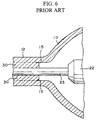
- the side tube 11 is heated only as far as in front of the ends of the cylindrical retaining bodies 30, shrunken regions 12 are formed which are not welded at the ends of the cylindrical retaining bodies 30, as shown in Fig. 6 because the part of the side tube 11 which corresponds to the ends of the cylindrical retaining bodies 30 is not heated.
- These areas form wedge-shaped gaps 15. This means that, in any case, in the corner areas of the faces of the shrunken regions 12 and the cylindrical retaining bodies 30, small wedge-shaped gaps 15 are formed.
- a primary object of the present invention is to devise a short arc lamp with a high lamp sustaining voltage in which there is no crack formation in the corner areas of the faces of the shrunken regions of a side tube and of the cylindrical retaining bodies for the upholding parts of the electrodes, even if the gas pressure is high during operation.
- this object is achieved by intermediate layers of metal or ceramic being located between the cylindrical retaining bodies and the shrunken regions, and by the cylindrical retaining bodies and the shrunken regions not being welded to one another, i.e. they are not formed into a single part.
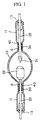
- Fig. 1 is a schematic representation of a xenon short arc lamp with a nominal power consumption of 10 kW.
- a cathode 21 and an anode 22 are attached to the tips of a pair of upholding parts 23 that have an outside diameter of 6 mm and are made of tungsten rods.
- the cathode 21 and anode 22 are disposed opposite one another within that arc to at a distance from one another of 15 mm.
- the arc tube 10 is filled with 7500 torr of xenon gas.
- a side tube 11 extends from each of opposite ends of the arc tube 10. In each of the sealed portions 13 on the ends of the side tube 11, a respective upholding part 23 is sealed.
- the respective upholding part 23 is inserted into a fused silica glass cylindrical retaining body 30 that has an outside diameter of 12 mm, an inside diameter of 6 mm and a length of 30 mm. This means that the upholding part of the electrode 23 is held by the cylindrical retaining body 30.
- the arc tube 10 is in a negative pressure state. Heating the ends of the side tube 11 on the sides of the arc tube 10 reduces the diameter of the side tube 11. Thus, shrunken regions 12 are formed. Between the cylindrical retaining bodies 30 and the shrunken regions 12 intermediate layers 40 of metal or ceramic are provided, as shown in Fig. 2. The cylindrical retaining bodies 30 and the shrunken regions 12 are attached without being fused into a single part by welding.
- molybdenum films can be used as intermediate layers 40.
- production of the shrunken regions is described.
- the outside peripheral surface of the respective cylindrical retaining body 30 is wound with roughly 1.5 turns of a molybdenum film that is 15 microns thick, as is illustrated in Fig. 3. If, in this case, the thickness of the molybdenum film is greater than 20 microns, during winding, a resetting spring force arises; this makes winding difficult. Therefore, it is preferred that the thickness of the molybdenum film be less at most 20 microns.
- the inside of the arc tube 10 is subjected to a negative pressure of roughly 1 x 10 -3 to 1 x 10 -4 torr and the side tube 11 is heated along the axial direction of the tube.
- a negative pressure roughly 1 x 10 -3 to 1 x 10 -4 torr
- the side tube 11 is heated along the axial direction of the tube.
- the diameter of the side tube 11 is reduced and shrunken regions 12 are formed.
- intermediate layers 40 of molybdenum films are present, the cylindrical retaining bodies 30 and the shrunken regions 12 are attached without their being welded into a single piece.
- the retaining body 30 need not be a genuine cylinder, but also a polygonal cylinder with at least five corners or a cylinder in which the two ends are tapered and the diameter reduced can be used.
- the lamp operating sustaining voltage can be increased. Crack formation is also prevented in a bright xenon short arc lamp with increased xenon gas pressure. Thus, lamp breakage can be prevented.
- Vacuum evaporated metal layers or sintered ceramic layers can also be used as the intermediate layer 40. Consequently, an example is described in which on the outer peripheral surface of the respective cylindrical retaining body 30 has molybdenum vacuum evaporated thereon by sputtering.
- a magnetron sputter device is used with a capture electrode made of metallic molybdenum and with a high frequency input power current source of 500 W.
- the cylindrical retaining body 30, as a workpiece, is arranged in argon gas of 10 cc/10 min and 2 Pa roughly 22 cm away from the metallic molybdenum of the capture electrode and is moved with a speed of 1 micron/minute as it is turned.
- argon gas 10 cc/10 min and 2 Pa roughly 22 cm away from the metallic molybdenum of the capture electrode and is moved with a speed of 1 micron/minute as it is turned.
- a 1 micron thick layer of molybdenum is vacuum evaporated onto the outside peripheral surface of the cylindrical retaining body 30.
- the inside of the arc tube 10 is subjected to negative pressure and heated, as was described above.
- the shrunken region 12 is formed.
- the cylindrical retaining body 30 and the shrunken region 12 are attached without being welded together, and therefore, not becoming integral because the intermediate layer 40 of vacuum evaporated molybdenum film is present.
- Welding of the cylindrical retaining bodies 30 and shrunken regions 12 to one another can be adequately prevented when the thickness of the vacuum evaporated molybdenum film is at least equal to 1 micron.
- a ceramic layer is used as the intermediate layer 40, powdered ceramic of aluminum oxide, zirconia, silicon carbide, tantalum carbide, titanium oxide or the like can be dissolved in a binder and thus a solution for application can be produced, which is applied in a given thickness on the outside peripheral surface of the respective cylindrical retaining body 30. By heating and sintering, a ceramic layer can be produced.
- shrunken regions 12 are formed by the above described process. Since the intermediate layer 40 of ceramic is present, the cylindrical retaining bodies 30 and the shrunken regions 12 are attached, also in this case, without being directly welded to one another and without being integrally formed.
- the short arc lamp of the invention between the cylindrical retaining bodies for the upholding parts of the electrodes and the shrunken regions of the side tube, there is at least one intermediate layer of metal or ceramic.
- welding of the cylindrical retaining bodies and the shrunken regions to one another can be prevented.
- the lamp is prevented from being destroyed in the corner regions of the faces of the shrunken regions and the cylindrical retaining bodies, so that the operating sustaining voltage can be increased and a bright short arc lamp obtained.
Landscapes
- Physics & Mathematics (AREA)
- Engineering & Computer Science (AREA)
- Plasma & Fusion (AREA)
- General Physics & Mathematics (AREA)
- Vessels And Coating Films For Discharge Lamps (AREA)
Applications Claiming Priority (3)
| Application Number | Priority Date | Filing Date | Title |
|---|---|---|---|
| JP31464997 | 1997-10-31 | ||
| JP314649/97 | 1997-10-31 | ||
| JP31464997A JP3430887B2 (ja) | 1997-10-31 | 1997-10-31 | ショートアークランプ |
Publications (3)
| Publication Number | Publication Date |
|---|---|
| EP0913855A2 true EP0913855A2 (de) | 1999-05-06 |
| EP0913855A3 EP0913855A3 (de) | 1999-06-30 |
| EP0913855B1 EP0913855B1 (de) | 2002-07-03 |
Family
ID=18055878
Family Applications (1)
| Application Number | Title | Priority Date | Filing Date |
|---|---|---|---|
| EP98120496A Expired - Lifetime EP0913855B1 (de) | 1997-10-31 | 1998-10-29 | Kurzbogenlampe |
Country Status (4)
| Country | Link |
|---|---|
| US (1) | US6356018B1 (de) |
| EP (1) | EP0913855B1 (de) |
| JP (1) | JP3430887B2 (de) |
| DE (1) | DE69806327T2 (de) |
Cited By (4)
| Publication number | Priority date | Publication date | Assignee | Title |
|---|---|---|---|---|
| EP1047111A3 (de) * | 1999-04-23 | 2004-07-28 | Ushiodenki Kabushiki Kaisha | Kurzbogen-Entladungslampe |
| WO2008083700A1 (de) * | 2006-12-22 | 2008-07-17 | Osram Gesellschaft mit beschränkter Haftung | Lampenvorrichtung und verfahren zur herstellung einer lampenvorrichtung |
| DE102007020067A1 (de) * | 2007-04-27 | 2008-11-06 | Osram Gesellschaft mit beschränkter Haftung | Verfahren zur Herstellung einer Molybdänfolie für den Lampenbau und Molybdänfolie sowie Lampe mit Molybdänfolie |
| DE10305339B4 (de) * | 2002-02-13 | 2009-07-02 | Ushiodenki K.K. | Kurzbogen-Entladungslampe |
Families Citing this family (13)
| Publication number | Priority date | Publication date | Assignee | Title |
|---|---|---|---|---|
| JP2001015070A (ja) * | 1999-06-29 | 2001-01-19 | Ushio Inc | 放電ランプ |
| DE60039657D1 (de) * | 1999-07-02 | 2008-09-11 | Phoenix Electric Co Ltd | Aufbauanordnung für Lampe und Dichtungsstruktur einer Lampe mit einer solchen Aufbauanordnung |
| JP3636654B2 (ja) * | 2000-11-14 | 2005-04-06 | 株式会社小糸製作所 | アークチューブ |
| JP3687582B2 (ja) * | 2001-09-12 | 2005-08-24 | ウシオ電機株式会社 | 放電ランプ |
| JP2003123992A (ja) * | 2001-10-17 | 2003-04-25 | Ushio Inc | キセノン放電ランプ点灯装置 |
| JP4036039B2 (ja) * | 2002-06-19 | 2008-01-23 | ウシオ電機株式会社 | ショートアーク型放電ランプ |
| JP2004178894A (ja) * | 2002-11-26 | 2004-06-24 | Ushio Inc | ショートアーク型放電ランプ |
| DE102004002455A1 (de) * | 2003-03-14 | 2004-09-23 | Patent-Treuhand-Gesellschaft für elektrische Glühlampen mbH | Lampe mit fixiertem Glasbauteil |
| JP4042605B2 (ja) * | 2003-03-31 | 2008-02-06 | ウシオ電機株式会社 | キセノンランプ |
| JP4358729B2 (ja) * | 2004-12-22 | 2009-11-04 | 株式会社オーク製作所 | ショートアーク型放電灯 |
| DE102005046483A1 (de) * | 2005-09-28 | 2007-03-29 | Patent-Treuhand-Gesellschaft für elektrische Glühlampen mbH | Entladungslampe |
| JP2007290233A (ja) * | 2006-04-25 | 2007-11-08 | Ushio Inc | 光照射器およびインクジェットプリンタ |
| JP5696878B2 (ja) * | 2010-11-17 | 2015-04-08 | ウシオ電機株式会社 | キセノンショートアークランプ |
Family Cites Families (7)
| Publication number | Priority date | Publication date | Assignee | Title |
|---|---|---|---|---|
| NL7506655A (nl) * | 1975-06-05 | 1976-12-07 | Philips Nv | Korte-boog ontladingslamp. |
| NL182439C (nl) | 1978-05-23 | 1988-03-01 | Philips Nv | Korteboogontladingslamp. |
| JP2621891B2 (ja) | 1987-12-07 | 1997-06-18 | 東芝ライテック株式会社 | 高圧放電灯 |
| JPH04101348A (ja) | 1990-08-17 | 1992-04-02 | Ushio Inc | 高圧放電灯 |
| JP3166526B2 (ja) | 1994-12-22 | 2001-05-14 | ウシオ電機株式会社 | ショートアーク型放電ランプ |
| JPH1021882A (ja) | 1996-06-28 | 1998-01-23 | Toshiba Lighting & Technol Corp | 高圧放電ランプ,照射装置,点灯装置および露光装置 |
| JPH10149801A (ja) | 1996-11-19 | 1998-06-02 | Iwasaki Electric Co Ltd | ショートアーク型放電ランプ |
-
1997
- 1997-10-31 JP JP31464997A patent/JP3430887B2/ja not_active Expired - Lifetime
-
1998
- 1998-10-28 US US09/181,604 patent/US6356018B1/en not_active Expired - Lifetime
- 1998-10-29 EP EP98120496A patent/EP0913855B1/de not_active Expired - Lifetime
- 1998-10-29 DE DE69806327T patent/DE69806327T2/de not_active Expired - Lifetime
Cited By (6)
| Publication number | Priority date | Publication date | Assignee | Title |
|---|---|---|---|---|
| EP1047111A3 (de) * | 1999-04-23 | 2004-07-28 | Ushiodenki Kabushiki Kaisha | Kurzbogen-Entladungslampe |
| DE10305339B4 (de) * | 2002-02-13 | 2009-07-02 | Ushiodenki K.K. | Kurzbogen-Entladungslampe |
| WO2008083700A1 (de) * | 2006-12-22 | 2008-07-17 | Osram Gesellschaft mit beschränkter Haftung | Lampenvorrichtung und verfahren zur herstellung einer lampenvorrichtung |
| US8084944B2 (en) | 2006-12-22 | 2011-12-27 | Osram Ag | Lamp device and method for the production of a lamp device |
| DE102007020067A1 (de) * | 2007-04-27 | 2008-11-06 | Osram Gesellschaft mit beschränkter Haftung | Verfahren zur Herstellung einer Molybdänfolie für den Lampenbau und Molybdänfolie sowie Lampe mit Molybdänfolie |
| DE102007020067B4 (de) * | 2007-04-27 | 2013-07-18 | Osram Gmbh | Verfahren zur Herstellung einer Molybdänfolie für den Lampenbau und Molybdänfolie sowie Lampe mit Molybdänfolie |
Also Published As
| Publication number | Publication date |
|---|---|
| US20020021091A1 (en) | 2002-02-21 |
| US6356018B1 (en) | 2002-03-12 |
| EP0913855B1 (de) | 2002-07-03 |
| JPH11135067A (ja) | 1999-05-21 |
| JP3430887B2 (ja) | 2003-07-28 |
| DE69806327T2 (de) | 2003-02-27 |
| DE69806327D1 (de) | 2002-08-08 |
| EP0913855A3 (de) | 1999-06-30 |
Similar Documents
| Publication | Publication Date | Title |
|---|---|---|
| EP0913855B1 (de) | Kurzbogenlampe | |
| KR100944818B1 (ko) | 쇼트 아크 고압 방전 램프 | |
| EP0866488A1 (de) | Hochdruckentladungslampe und Verfahren zu seiner Herstellung | |
| US6815892B2 (en) | Discharge lamp with metal oxide coating | |
| CN1217375C (zh) | 带介电阻挡层的放电灯 | |
| JP2019194982A (ja) | 放電ランプ用の電極、放電ランプおよび電極を製造する方法 | |
| US6369509B1 (en) | Short arc lamp with crack-preventing electric mounting arrangement | |
| KR100822583B1 (ko) | 고압 방전 램프 | |
| US4625149A (en) | Metal vapor discharge lamp including an inner burner having tapered ends | |
| JP3858718B2 (ja) | ショートアーク放電ランプ | |
| US7038379B2 (en) | High pressure discharge lamp and method for sealing a bulb thereof | |
| EP1308987A2 (de) | Quecksilber-Höchstdruck-Entladungslampe vom Kurzbogentyp | |
| JP5446218B2 (ja) | 放電ランプ | |
| JPH1125915A (ja) | 管球の閉塞部構造体 | |
| EP1729325B1 (de) | Ultrahochdruck-Quecksilberlampe | |
| KR20160117190A (ko) | 방전 램프 | |
| CN101887838B (zh) | 高压放电灯 | |
| JP7313791B2 (ja) | 放電ランプ及び放電ランプの電極の製造方法 | |
| CN100449677C (zh) | 短弧放电灯 | |
| KR102742209B1 (ko) | 방전 램프 | |
| KR102758050B1 (ko) | 방전 램프 | |
| JP2000003695A (ja) | 放電ランプ | |
| TW202531312A (zh) | 放電燈 | |
| JP2003282024A (ja) | 高圧放電灯およびそのバルブの封止方法 | |
| KR20070093969A (ko) | 냉음극 형광램프 |
Legal Events
| Date | Code | Title | Description |
|---|---|---|---|
| PUAI | Public reference made under article 153(3) epc to a published international application that has entered the european phase |
Free format text: ORIGINAL CODE: 0009012 |
|
| AK | Designated contracting states |
Kind code of ref document: A2 Designated state(s): DE FR GB |
|
| AX | Request for extension of the european patent |
Free format text: AL;LT;LV;MK;RO;SI |
|
| PUAL | Search report despatched |
Free format text: ORIGINAL CODE: 0009013 |
|
| RIC1 | Information provided on ipc code assigned before grant |
Free format text: 6H 01J 61/36 A, 6H 01J 61/86 B, 6H 01J 61/32 B |
|
| AK | Designated contracting states |
Kind code of ref document: A3 Designated state(s): AT BE CH CY DE DK ES FI FR GB GR IE IT LI LU MC NL PT SE |
|
| AX | Request for extension of the european patent |
Free format text: AL;LT;LV;MK;RO;SI |
|
| 17P | Request for examination filed |
Effective date: 19990625 |
|
| AKX | Designation fees paid |
Free format text: DE FR GB |
|
| GRAG | Despatch of communication of intention to grant |
Free format text: ORIGINAL CODE: EPIDOS AGRA |
|
| GRAG | Despatch of communication of intention to grant |
Free format text: ORIGINAL CODE: EPIDOS AGRA |
|
| GRAH | Despatch of communication of intention to grant a patent |
Free format text: ORIGINAL CODE: EPIDOS IGRA |
|
| 17Q | First examination report despatched |
Effective date: 20011130 |
|
| GRAH | Despatch of communication of intention to grant a patent |
Free format text: ORIGINAL CODE: EPIDOS IGRA |
|
| GRAA | (expected) grant |
Free format text: ORIGINAL CODE: 0009210 |
|
| AK | Designated contracting states |
Kind code of ref document: B1 Designated state(s): DE FR GB |
|
| REF | Corresponds to: |
Ref document number: 69806327 Country of ref document: DE Date of ref document: 20020808 |
|
| ET | Fr: translation filed | ||
| PLBE | No opposition filed within time limit |
Free format text: ORIGINAL CODE: 0009261 |
|
| STAA | Information on the status of an ep patent application or granted ep patent |
Free format text: STATUS: NO OPPOSITION FILED WITHIN TIME LIMIT |
|
| 26N | No opposition filed |
Effective date: 20030404 |
|
| REG | Reference to a national code |
Ref country code: FR Ref legal event code: PLFP Year of fee payment: 19 |
|
| REG | Reference to a national code |
Ref country code: FR Ref legal event code: PLFP Year of fee payment: 20 |
|
| PGFP | Annual fee paid to national office [announced via postgrant information from national office to epo] |
Ref country code: FR Payment date: 20170918 Year of fee payment: 20 |
|
| PGFP | Annual fee paid to national office [announced via postgrant information from national office to epo] |
Ref country code: DE Payment date: 20171025 Year of fee payment: 20 |
|
| PGFP | Annual fee paid to national office [announced via postgrant information from national office to epo] |
Ref country code: GB Payment date: 20171025 Year of fee payment: 20 |
|
| REG | Reference to a national code |
Ref country code: DE Ref legal event code: R071 Ref document number: 69806327 Country of ref document: DE |
|
| REG | Reference to a national code |
Ref country code: GB Ref legal event code: PE20 Expiry date: 20181028 |
|
| PG25 | Lapsed in a contracting state [announced via postgrant information from national office to epo] |
Ref country code: GB Free format text: LAPSE BECAUSE OF EXPIRATION OF PROTECTION Effective date: 20181028 |