EP0913914A1 - Machine électrique à double excitation, et notamment alternateur de véhicule automobile - Google Patents
Machine électrique à double excitation, et notamment alternateur de véhicule automobile Download PDFInfo
- Publication number
- EP0913914A1 EP0913914A1 EP98402484A EP98402484A EP0913914A1 EP 0913914 A1 EP0913914 A1 EP 0913914A1 EP 98402484 A EP98402484 A EP 98402484A EP 98402484 A EP98402484 A EP 98402484A EP 0913914 A1 EP0913914 A1 EP 0913914A1
- Authority
- EP
- European Patent Office
- Prior art keywords
- rotor
- stator
- excitation
- machine according
- establishing
- Prior art date
- Legal status (The legal status is an assumption and is not a legal conclusion. Google has not performed a legal analysis and makes no representation as to the accuracy of the status listed.)
- Granted
Links
- 230000005284 excitation Effects 0.000 title claims abstract description 47
- 238000004804 winding Methods 0.000 claims abstract description 30
- 230000004907 flux Effects 0.000 claims abstract description 23
- 230000005291 magnetic effect Effects 0.000 claims abstract description 21
- 230000005415 magnetization Effects 0.000 claims description 3
- 239000007858 starting material Substances 0.000 claims description 3
- 230000005417 remagnetization Effects 0.000 claims description 2
- 230000033228 biological regulation Effects 0.000 description 4
- 230000002457 bidirectional effect Effects 0.000 description 2
- 230000001105 regulatory effect Effects 0.000 description 2
- 230000006378 damage Effects 0.000 description 1
- 230000007423 decrease Effects 0.000 description 1
- 230000009977 dual effect Effects 0.000 description 1
- 230000005294 ferromagnetic effect Effects 0.000 description 1
- 238000009434 installation Methods 0.000 description 1
- 239000000696 magnetic material Substances 0.000 description 1
- 238000012423 maintenance Methods 0.000 description 1
- 239000000463 material Substances 0.000 description 1
- 239000004065 semiconductor Substances 0.000 description 1
Images

Classifications
-
- H—ELECTRICITY
- H02—GENERATION; CONVERSION OR DISTRIBUTION OF ELECTRIC POWER
- H02K—DYNAMO-ELECTRIC MACHINES
- H02K21/00—Synchronous motors having permanent magnets; Synchronous generators having permanent magnets
- H02K21/02—Details
- H02K21/04—Windings on magnets for additional excitation ; Windings and magnets for additional excitation
- H02K21/042—Windings on magnets for additional excitation ; Windings and magnets for additional excitation with permanent magnets and field winding both rotating
-
- H—ELECTRICITY
- H02—GENERATION; CONVERSION OR DISTRIBUTION OF ELECTRIC POWER
- H02K—DYNAMO-ELECTRIC MACHINES
- H02K16/00—Machines with more than one rotor or stator
- H02K16/04—Machines with one rotor and two stators
Definitions
- the present invention relates generally to rotary machines such as alternators for motor vehicles.
- the single or multi-phase generator that constitutes a conventional alternator of motor vehicle generally comprises a stator inside which turns a rotor provided with an excitation winding. This winding is powered by brushes contact with two slip rings provided on a projecting part of the shaft of the rotor.
- the present invention aims to overcome these drawbacks and to propose a machine rotating, in particular an alternator, in which the regulation of the current delivered can be done by playing on excitement, and in which, despite the use of permanent magnets to perform this excitation, this can be varied between a zero or essentially zero excitation and maximum excitation.
- Another object of the invention is to provide a machine in which the excitation varies within such limits thanks to the application of an excitation current which also varies between a zero value and a maximum value.
- Another object of the invention is to propose a structure of a rotating machine with double air gap and a single rotor which is axially compact and of a power greater mass.
- the present invention provides an electrical machine with switching flux, comprising a stator and a rotor, the stator comprising at least one winding armature housed in at least one pair of notches, the rotor comprising means capable of selectively establishing closed magnetic circuits passing around the strands armature winding (s), characterized in that said means comprise at less a permanent magnet able to establish a magnetic flux looping around it even in a circumferential direction of the rotor, and at least one winding excitation capable of locally establishing a magnetic flux adjustable in one direction circumferential opposite to that of the flux produced by the magnet (s).
- Such a regulatory structure indeed allows the use of a regulator classic with a switch for adjusting the excitation, which divides by four the cost due to switches compared to bidirectional current machines.
- the rotor comprises along its periphery an alternation a plurality of permanent magnets and excitation coils.
- the rotor has an alternation of a plurality permanent magnets and H-shaped structures, which define notches in which excitation coils are received.
- the machine includes an internal stator and a stator. external.
- Such a structure is advantageously used as an alternator-starter with high specific power since it is axially compact and must deliver high output power on both stators.
- the invention also relates to a rotor of a hybrid electric machine with double excitation of the aforementioned type.
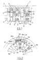
- FIG. 1 there is shown a stator 1 and a rotor 5 able to equip a single-phase electric machine according to the invention.
- the stator 1 comprises an annular carcass 2 made up of two parts which define a continuous annular structure. At the inner periphery of this structure a plurality of notches 3 are provided which receive the strands of an armature coil 4. These notches 3 are in an even number and are regularly distributed around the periphery of the stator 1.
- the rotor 5 is defined by a succession of structures 6 in H, which alternate with housings 7 in which permanent magnets 8 are received.
- the exterior and interior notches 6a and 6b defined by the structures 6 in H receive the strands 9 of an excitation coil, which are connected to means 10 for their supply by an adjustable excitation current.
- These structures 6 in H and the permanent magnets 8 are regularly distributed over the rotor 5.
- the number of magnets 8 and the number of structures 6 in H correspond to one and the other to the number of pairs of poles of the rotating machine, i.e. half the number of notches 3. More precisely, the magnets 8 and the structures 6 in H are distributed so that when an outer notch 6a is in line with a notch 3 of the stator, the magnets 8 on either side of this H-shaped structure are at the right of notches 3 which are on either side of the first notch 3.
- the N / S orientation of the permanent magnets 8 is such that in the absence of current in the coils 9, they generate an essentially circumferential magnetic flux on the rotor 5, in the direction of the arrows indicated in Figure 1.
- this electromotive force depends on the amplitude of the magnetic field created by the excitation coil 9, to vary between a value substantially zero and a maximum value.
- the magnets 8 and the excitation coil 9 are dimensioned so that the fluxes of the excitation coil are of the same order of magnitude as those of the magnet, for reasonable excitation current intensities.
- the regulation is for example carried out by means of a single controlled transistor by a regulation microprocessor.
- This machine in this case three-phase, comprises a rotor 105 which is identical to that of FIG. 1 and which comprises a plurality of structures 106 in H which alternate with permanent magnets 108, the recesses defined by these H-shaped structures receiving the strands of an excitation coil 109.
- the permanent magnets 108 are received in housings 107 whose depth is slightly less than the radial thickness of the rotor 105.
- the stator 121 is continuous in the circumferential direction and is produced so conventional by stacking sheets.
- This stator 121 has six notches 103 per pair rotor poles, these different notches 103 being defined by internal teeth 122 distributed angularly in an essentially regular manner. These notches 103 receive the distributed strands of the different phase windings 104a, 104b, 104c, three successive notches 103 at the periphery of the stator respectively comprising strands of said three phase windings.
- the permanent magnets 108 cooperate to produce a flux magnetic flow practically only in the rotor, and the phase windings stator therefore deliver a substantially zero current.
- the rotors 5 and 105 are fitted on trees (not shown) in non-magnetic or isolated materials sets of permanent magnets / H-structures / excitation coils by non-magnetic materials.
- the rotor is mounted between an external stator and an internal stator.
- the machine illustrated in these Figures 3 and 4 includes an external stator 201 and a rotor 205 identical to the stator 1 and to the rotor 5.
- the rotor 205 consists of a succession of parts 206 in H alternating with permanent magnets 208, the notches defined by the H-pieces strands of an excitation coil 209.
- the external stator 201 is constituted by a stack of sheets and it has on its inner periphery a succession of notches 203 receiving a winding armature 204.
- the rotor 205 rotates between this external stator 201 and an internal stator 211 which is also consisting of a stack of sheets and present at its inner periphery a succession of notches 213 also receiving an armature winding 214.
- the number of notches 213 is identical to the number of notches 203, said notches 213 being arranged in line with said notches 203.
- this structure is advantageously suitable for making a machine three-phase dual voltage, the first stator being able to operate at 14 volts, the second at 24 volts, 48 volts or 96 volts depending on the needs of the vehicle's on-board network
- FIGS. 1 to 4 can do so if necessary be subjected to an initial magnetization or to a re-magnetization.
- the magnets are mounted in the stator without having been previously magnetized, it suffices to supply the excitation windings with a reverse current of normal excitation current.
- a field circumferential magnetic in the same direction as that produced by permanent magnets, and this field is capable of magnetizing or remagnetizing the magnets.
- This establishment of a reverse field of magnetization or remagnetization can be performed for example using semiconductor switching means, that the skilled person will be able to develop without difficulty. This operation can be carried out either on board the vehicle, using the electrical energy supplied by the battery, or workshop as part of a maintenance operation.
- the assembly of the rotor on the stators is made easier by the fact that the flow of permanent magnets closes in the rotor, there is no risk of the rotor structure getting stuck on the parts ferromagnetic elements which constitute in particular the internal or external stators.
- the new structures proposed allow a yield improvement of 10 to 20%.
Landscapes
- Engineering & Computer Science (AREA)
- Power Engineering (AREA)
- Permanent Magnet Type Synchronous Machine (AREA)
- Synchronous Machinery (AREA)
- Control Of Eletrric Generators (AREA)
- Permanent Field Magnets Of Synchronous Machinery (AREA)
- Windings For Motors And Generators (AREA)
Abstract
Description
Claims (10)
- Machine électrique, comportant au moins un stator (1, 101 ; 201, 211) et un rotor (5, 105 ; 205), le stator (1, 101 ; 201, 211) comportant au moins un bobinage d'induit logé dans au moins une paire d'encoches, le rotor (5, 105, 205) comportant des moyens aptes à sélectivement établir des circuits magnétiques fermés passant autour des brins du ou des bobinages d'induits, caractérisée en ce que lesdits moyens comprennent au moins un aimant (8, 108, 208) permanent apte à établir un flux magnétique se bouclant sur lui même dans une direction circonférentielle du rotor (5, 105, 205), et au moins un bobinage d'excitation (9, 109, 209) apte à établir localement un flux magnétique réglable dans une direction circonférentielle inverse de celle du flux produit par le ou les aimants (8, 108, 208).
- Machine selon la revendication 1, caractérisée en ce que le rotor (5, 105 ; 05) comporte le long de sa périphérie une alternance d'une pluralité d'aimants (8, 108, 208) permanents et de bobinages d'excitation (9, 109, 209).
- Machine selon l'une des revendications 1 et 2, caractérisée en ce que le rotor (5, 105 ; 05) présente une alternance d'une pluralité d'aimants (8, 108, 208) permanents et de structures en H, qui définissent des encoches dans lesquelles les bobinages d'excitation (9, 109, 209) sont reçus.
- Machine selon l'une des revendications 1 à 3, caractérisée en ce qu'elle comporte un stator (1, 101 ; 201, 211) interne et un stator (1, 101 ; 201, 211) externe.
- Machine selon la revendication 4, caractérisé en ce que les deux stators (201, 211) comportent le même nombre d'encoches, lesdites encoches s'étendant au droit les unes des autres.
- Machine selon l'une des revendications 1 à 5, caractérisée en ce qu'elle comprend des moyens pour établir à l'aide du ou des bobinages d'excitation (9, 109, 209) un champ magnétique inverse de magnétisation ou de remagnétisation du ou des aimants (8, 108, 208) permanents.
- Alternateur de véhicule automobile, caractérisé en ce qu'il est constitué par une machine selon l'une des revendications 1 à 6.
- Machine tournante bi-tension, caractérisée en ce qu'elle est constituée par une machine selon l'une des revendications 5 et 6.
- Alternateur-démarreur, caractérisé en ce qu'il est constitué par une machine selon la revendication 8.
- Rotor de machine électrique hybride à double excitation comportant des moyens aptes à sélectivement établir des circuits magnétiques fermés passant autour des brins du ou des bobinages d'induits, caractérisé en ce que lesdits moyens comprennent au moins un aimant permanent apte à établir un flux magnétique se bouclant sur lui même dans une direction circonférentielle dudit rotor (5, 105 ; 205), et au moins un bobinage d'excitation (9, 109, 209) apte à établir localement un flux magnétique réglable dans une direction circonférentielle inverse de celle du flux produit par le ou les aimants (8, 108, 208).
Applications Claiming Priority (2)
| Application Number | Priority Date | Filing Date | Title |
|---|---|---|---|
| FR9712472 | 1997-10-07 | ||
| FR9712472A FR2769423B1 (fr) | 1997-10-07 | 1997-10-07 | Machine electrique a double excitation, et notamment alternateur de vehicule automobile |
Publications (2)
| Publication Number | Publication Date |
|---|---|
| EP0913914A1 true EP0913914A1 (fr) | 1999-05-06 |
| EP0913914B1 EP0913914B1 (fr) | 2008-10-29 |
Family
ID=9511905
Family Applications (1)
| Application Number | Title | Priority Date | Filing Date |
|---|---|---|---|
| EP98402484A Expired - Lifetime EP0913914B1 (fr) | 1997-10-07 | 1998-10-07 | Machine électrique à double excitation, et notamment alternateur de véhicule automobile |
Country Status (9)
| Country | Link |
|---|---|
| US (1) | US6093992A (fr) |
| EP (1) | EP0913914B1 (fr) |
| JP (1) | JP4264150B2 (fr) |
| KR (1) | KR100595076B1 (fr) |
| CN (1) | CN1096739C (fr) |
| BR (1) | BR9803827B1 (fr) |
| DE (1) | DE69840160D1 (fr) |
| ES (1) | ES2314987T3 (fr) |
| FR (1) | FR2769423B1 (fr) |
Cited By (5)
| Publication number | Priority date | Publication date | Assignee | Title |
|---|---|---|---|---|
| EP0942510B1 (fr) * | 1998-03-09 | 2008-07-23 | Valeo Equipements Electriques Moteur | Machine électrique à double excitation, et notamment alternateur de véhicule automobile |
| CN105811696A (zh) * | 2016-04-27 | 2016-07-27 | 大连名阳实业有限公司 | 混合励磁型复合磁通切换永磁电机 |
| EP2782226B1 (fr) * | 2013-03-20 | 2021-03-10 | Hamilton Sundstrand Corporation | Rotor de machine électrique à aimants permanents avec flux magnétique contrôlé |
| EP4018532A4 (fr) * | 2019-10-03 | 2022-10-26 | Magna International Inc. | Machines synchrones à champ enroulé et commande |
| US20230024385A1 (en) * | 2021-07-14 | 2023-01-26 | Hyundai Motor Company | Hybrid induction motor including dual stator |
Families Citing this family (37)
| Publication number | Priority date | Publication date | Assignee | Title |
|---|---|---|---|---|
| FR2786956B1 (fr) * | 1998-12-07 | 2001-02-16 | Centre Nat Rech Scient | Machine electrique tournante a double excitation perfectionnee |
| JP3466591B2 (ja) * | 2001-07-23 | 2003-11-10 | 三菱電機株式会社 | 回転電機 |
| US20030057789A1 (en) * | 2001-09-21 | 2003-03-27 | Buening Duane Joseph | Five phase alternating current generator |
| US6750628B2 (en) | 2001-12-03 | 2004-06-15 | Electric Boat Corporation | Flux shunt wave shape control arrangement for permanent magnet machines |
| US6794790B2 (en) * | 2002-03-20 | 2004-09-21 | Denso Corporation | Rotary electric machine |
| US20060071576A1 (en) * | 2002-09-27 | 2006-04-06 | Yun-Hyun Cho | Flat board type brushless dc motor |
| US7112907B2 (en) * | 2003-12-12 | 2006-09-26 | Siemens Vdo Automotive Inc. | Flux modifier for a permanent magnet brush-type motor using wound field coils combined with permanent magnets |
| US7230363B2 (en) * | 2004-03-30 | 2007-06-12 | Honeywell International, Inc. | Low profile generator configuration |
| US7355309B2 (en) * | 2004-08-06 | 2008-04-08 | Northern Power Systems, Inc. | Permanent magnet rotor for a direct drive generator or a low speed motor |
| DE102004045992A1 (de) * | 2004-09-22 | 2006-04-06 | Siemens Ag | Elektrische Maschine |
| DE102005063271A1 (de) * | 2005-12-30 | 2007-07-19 | Robert Bosch Gmbh | Generator, insbesondere für Kraftfahrzeuge |
| US7719147B2 (en) | 2006-07-26 | 2010-05-18 | Millennial Research Corporation | Electric motor |
| WO2008133163A1 (fr) | 2007-04-23 | 2008-11-06 | Honda Motor Co., Ltd. | Rotor pour une machine rotative |
| ES2777794T3 (es) | 2008-08-15 | 2020-08-06 | Millennial Res Corporation | Motor regenerativo y bobina |
| US10038349B2 (en) | 2008-08-15 | 2018-07-31 | Millennial Research Corporation | Multi-phase modular coil element for electric motor and generator |
| JP5412121B2 (ja) * | 2009-01-27 | 2014-02-12 | 本田技研工業株式会社 | 永久磁石式回転子およびそれを備えた電動機 |
| JP5477161B2 (ja) | 2010-05-20 | 2014-04-23 | 株式会社デンソー | ダブルステータ型モータ |
| TWM403842U (en) * | 2010-11-26 | 2011-05-11 | Tai-Liang Chen | Structure of power generator with internal and external stators and non-magnetic rotor |
| KR101216857B1 (ko) * | 2011-02-25 | 2013-01-09 | 조윤현 | 스위치드 릴럭턴스 회전기기 |
| JP5472254B2 (ja) * | 2011-10-21 | 2014-04-16 | 株式会社デンソー | ダブルステータ型モータ |
| JP5488625B2 (ja) * | 2012-02-13 | 2014-05-14 | 株式会社デンソー | ダブルステータ型同期モータ |
| JP6044382B2 (ja) * | 2013-02-20 | 2016-12-14 | 株式会社デンソー | マルチギャップ型回転電機 |
| CN103390978B (zh) * | 2013-07-18 | 2016-03-16 | 东南大学 | 一种双定子盘式混合励磁电机 |
| JP6176217B2 (ja) * | 2014-10-02 | 2017-08-09 | トヨタ自動車株式会社 | 磁石レス回転電機 |
| KR101531932B1 (ko) * | 2014-12-16 | 2015-06-26 | (주)썬테크 | 고효율 전력전달이 가능한 영구자석 여자기 및 발전기 |
| CN104506011B (zh) * | 2014-12-18 | 2017-05-03 | 江苏大学 | 一种适用于增程式电动汽车的磁通切换永磁电机 |
| CN104539125B (zh) * | 2015-01-19 | 2017-07-11 | 上海电机学院 | 一种混合励磁磁通切换电机 |
| CN104811001B (zh) * | 2015-04-14 | 2017-03-29 | 鲁东大学 | 一种磁通切换型横向磁通永磁直线电机 |
| CN105391260B (zh) * | 2015-11-16 | 2018-01-16 | 江苏大学 | 双定子永磁游标直线电机及增加磁场调制效应的设计方法 |
| CN105978269B (zh) * | 2016-05-05 | 2018-08-21 | 南京航空航天大学 | 聚磁型无源转子横向磁通混合励磁单相电机 |
| JP6638615B2 (ja) * | 2016-09-29 | 2020-01-29 | 株式会社デンソー | 同期回転電機 |
| CN107070024B (zh) * | 2017-03-09 | 2019-03-29 | 东南大学 | 具有磁场调节能力的转子永磁型磁通切换电机 |
| CN109474155B (zh) * | 2018-12-13 | 2020-02-14 | 华中科技大学 | 一种双定子异步起动游标电机 |
| KR102326970B1 (ko) * | 2019-01-30 | 2021-11-16 | 명남수 | 전자기 기계용 권선 배열과 이를 이용한 이동 전자기 기계 |
| JP7541987B2 (ja) * | 2019-02-09 | 2024-08-29 | 南秀 明 | 多重多相巻線磁場ロックを利用する電磁機械 |
| IT202300027015A1 (it) * | 2023-12-18 | 2025-06-18 | Ferrari Spa | Motore elettrico per autotrazione e veicolo stradale dotato di tale motore |
| CN121566830A (zh) * | 2026-01-26 | 2026-02-24 | 江西理工大学 | 一种h型混合励磁反凸极永磁同步电机 |
Citations (5)
| Publication number | Priority date | Publication date | Assignee | Title |
|---|---|---|---|---|
| FR1527594A (fr) * | 1967-06-16 | 1968-05-31 | Westinghouse Electric Corp | Machines dynamo-électriques utilisant des aimants permanents de céramique |
| DE4139843C1 (en) * | 1991-12-03 | 1993-06-24 | Albert 7880 Bad Saeckingen De Mutter | Dynamoelectric machine, esp. for car - has salient pole laminated rotor with permanent magnets between poles plus extra slip ring-fed excitation winding |
| US5345133A (en) * | 1992-06-10 | 1994-09-06 | Okuma Corporation | Electric motor |
| WO1995000996A1 (fr) * | 1993-06-14 | 1995-01-05 | Ecoair Corp. | Alternateur hybride avec regulateur de tension |
| EP0723330A2 (fr) * | 1995-01-23 | 1996-07-24 | Siemens Aktiengesellschaft | Machine synchrone du type à jambe ou poles à griffes |
Family Cites Families (9)
| Publication number | Priority date | Publication date | Assignee | Title |
|---|---|---|---|---|
| FR2572599B1 (fr) * | 1984-10-31 | 1988-02-05 | Etri Sa | Moteur a courant continu |
| KR890011183A (ko) * | 1987-12-28 | 1989-08-14 | 김대원 | 다상 대칭 단극성 무정류자 직류전동기 |
| NL8801629A (nl) * | 1988-06-27 | 1990-01-16 | Philips Nv | Electrische meerpolige machine. |
| US5177391A (en) * | 1990-03-14 | 1993-01-05 | Nippondenso Co., Ltd. | Power generating apparatus |
| US5130590A (en) * | 1991-04-03 | 1992-07-14 | Tamagawa Seiki Kabushiki Kaisha | Brushless generator regulated by second rotor |
| EP0670622A1 (fr) * | 1994-03-04 | 1995-09-06 | BETA ENGINEERING S.n.c. di BBELLANDI G. & C. | Moteur électrique |
| FR2725566A1 (fr) * | 1994-10-10 | 1996-04-12 | Centre Nat Rech Scient | Actionneurs hybrides monophases a commutation de flux |
| KR970018938A (ko) * | 1995-09-28 | 1997-04-30 | 전성원 | 직류 모터 |
| JP3709590B2 (ja) * | 1995-11-02 | 2005-10-26 | 株式会社デンソー | 車両用交流発電機 |
-
1997
- 1997-10-07 FR FR9712472A patent/FR2769423B1/fr not_active Expired - Fee Related
-
1998
- 1998-10-02 JP JP28091298A patent/JP4264150B2/ja not_active Expired - Fee Related
- 1998-10-02 KR KR1019980041665A patent/KR100595076B1/ko not_active Expired - Fee Related
- 1998-10-05 US US09/166,787 patent/US6093992A/en not_active Expired - Lifetime
- 1998-10-07 ES ES98402484T patent/ES2314987T3/es not_active Expired - Lifetime
- 1998-10-07 EP EP98402484A patent/EP0913914B1/fr not_active Expired - Lifetime
- 1998-10-07 CN CN98124138A patent/CN1096739C/zh not_active Expired - Fee Related
- 1998-10-07 BR BRPI9803827-3A patent/BR9803827B1/pt not_active IP Right Cessation
- 1998-10-07 DE DE69840160T patent/DE69840160D1/de not_active Expired - Lifetime
Patent Citations (5)
| Publication number | Priority date | Publication date | Assignee | Title |
|---|---|---|---|---|
| FR1527594A (fr) * | 1967-06-16 | 1968-05-31 | Westinghouse Electric Corp | Machines dynamo-électriques utilisant des aimants permanents de céramique |
| DE4139843C1 (en) * | 1991-12-03 | 1993-06-24 | Albert 7880 Bad Saeckingen De Mutter | Dynamoelectric machine, esp. for car - has salient pole laminated rotor with permanent magnets between poles plus extra slip ring-fed excitation winding |
| US5345133A (en) * | 1992-06-10 | 1994-09-06 | Okuma Corporation | Electric motor |
| WO1995000996A1 (fr) * | 1993-06-14 | 1995-01-05 | Ecoair Corp. | Alternateur hybride avec regulateur de tension |
| EP0723330A2 (fr) * | 1995-01-23 | 1996-07-24 | Siemens Aktiengesellschaft | Machine synchrone du type à jambe ou poles à griffes |
Cited By (6)
| Publication number | Priority date | Publication date | Assignee | Title |
|---|---|---|---|---|
| EP0942510B1 (fr) * | 1998-03-09 | 2008-07-23 | Valeo Equipements Electriques Moteur | Machine électrique à double excitation, et notamment alternateur de véhicule automobile |
| EP2782226B1 (fr) * | 2013-03-20 | 2021-03-10 | Hamilton Sundstrand Corporation | Rotor de machine électrique à aimants permanents avec flux magnétique contrôlé |
| CN105811696A (zh) * | 2016-04-27 | 2016-07-27 | 大连名阳实业有限公司 | 混合励磁型复合磁通切换永磁电机 |
| EP4018532A4 (fr) * | 2019-10-03 | 2022-10-26 | Magna International Inc. | Machines synchrones à champ enroulé et commande |
| US20230024385A1 (en) * | 2021-07-14 | 2023-01-26 | Hyundai Motor Company | Hybrid induction motor including dual stator |
| US11876413B2 (en) * | 2021-07-14 | 2024-01-16 | Hyundai Motor Company | Hybrid induction motor including dual stator |
Also Published As
| Publication number | Publication date |
|---|---|
| BR9803827B1 (pt) | 2011-04-19 |
| US6093992A (en) | 2000-07-25 |
| FR2769423B1 (fr) | 1999-12-24 |
| CN1215241A (zh) | 1999-04-28 |
| JPH11164536A (ja) | 1999-06-18 |
| ES2314987T3 (es) | 2009-03-16 |
| EP0913914B1 (fr) | 2008-10-29 |
| DE69840160D1 (de) | 2008-12-11 |
| KR19990036863A (ko) | 1999-05-25 |
| FR2769423A1 (fr) | 1999-04-09 |
| CN1096739C (zh) | 2002-12-18 |
| BR9803827A (pt) | 2000-01-18 |
| JP4264150B2 (ja) | 2009-05-13 |
| KR100595076B1 (ko) | 2006-08-30 |
Similar Documents
| Publication | Publication Date | Title |
|---|---|---|
| EP0913914B1 (fr) | Machine électrique à double excitation, et notamment alternateur de véhicule automobile | |
| EP0909010B1 (fr) | Machine électrique à commutation de flux, et notamment alternateur de véhicule automobile | |
| EP1008223B1 (fr) | Machine tournante, tel qu'un alternateur pour vehicule automobile | |
| EP1529334A2 (fr) | Machine electrique tournante a double excitation autorisant un defluxage modulable | |
| EP0942510A1 (fr) | Machine électrique à double excitation, et notamment alternateur de véhicule automobile | |
| EP0932245B1 (fr) | Machine électrique à double excitation, et notamment alternateur de véhicule automobile | |
| EP0932244B1 (fr) | Machine électrique à double excitation, et notamment alternateur de véhicule automobile | |
| FR2959362A1 (fr) | Rotor de machine electrique tournante avec structures interpolaires | |
| EP0576307A1 (fr) | Moteur auto-synchrone et chaîne de traction électrique utilisant un moteur auto-synchrone | |
| EP4566151A1 (fr) | Machine electrique de traction a flux axial | |
| EP1082804B1 (fr) | Machine tournante comprenant des moyens d'excitation perfectionnes | |
| EP3053262B1 (fr) | Machine electrique tournante polyphasee a au moins cinq phases | |
| FR2641139A1 (fr) | ||
| FR3062252B1 (fr) | Machine electrique tournante de traction pour vehicule automobile a commutation de flux | |
| EP2866344B1 (fr) | Machine électrique tournante polyphasée à au moins cinq phases à commande optimisée | |
| EP3925061A1 (fr) | Machine électrique synchrone polyphasée à commutateur mécanique | |
| FR2775393A1 (fr) | Machine dynamo-electrique a reluctance variable hybride a effet vernier a grande plage et vitesse | |
| FR2906942A1 (fr) | Rotor a griffes muni d'elements ferromagnetiques interpolaires de largeur optimisee et machine tournante equipe d'un tel rotor | |
| WO2022003190A1 (fr) | Machine électrique synchrone équipée d'un commutateur mécanique | |
| WO2019170482A1 (fr) | Machine electrique tournante a bobinage fractionne | |
| FR2704369A1 (fr) | Moteur autosynchrone à bague commutante. | |
| FR3092712A1 (fr) | Machine électrique synchrone polyphasée à commutateur mécanique | |
| FR2780579A1 (fr) | Machine tournante, tel qu'un alternateur pour vehicule automobile | |
| FR2485287A1 (fr) | Machine electrique tournante a courant continu ou a courant alternatif redresse | |
| WO2022122653A1 (fr) | Machine électrique tournante pour contrôle pleine onde et à modulation de largeur d'impulsion et ensemble électrique |
Legal Events
| Date | Code | Title | Description |
|---|---|---|---|
| PUAI | Public reference made under article 153(3) epc to a published international application that has entered the european phase |
Free format text: ORIGINAL CODE: 0009012 |
|
| AK | Designated contracting states |
Kind code of ref document: A1 Designated state(s): DE ES GB IT |
|
| AX | Request for extension of the european patent |
Free format text: AL;LT;LV;MK;RO;SI |
|
| 17P | Request for examination filed |
Effective date: 19991025 |
|
| AKX | Designation fees paid |
Free format text: DE ES GB IT |
|
| 17Q | First examination report despatched |
Effective date: 20040908 |
|
| GRAP | Despatch of communication of intention to grant a patent |
Free format text: ORIGINAL CODE: EPIDOSNIGR1 |
|
| GRAS | Grant fee paid |
Free format text: ORIGINAL CODE: EPIDOSNIGR3 |
|
| GRAA | (expected) grant |
Free format text: ORIGINAL CODE: 0009210 |
|
| AK | Designated contracting states |
Kind code of ref document: B1 Designated state(s): DE ES GB IT |
|
| REG | Reference to a national code |
Ref country code: GB Ref legal event code: FG4D Free format text: NOT ENGLISH |
|
| REF | Corresponds to: |
Ref document number: 69840160 Country of ref document: DE Date of ref document: 20081211 Kind code of ref document: P |
|
| REG | Reference to a national code |
Ref country code: ES Ref legal event code: FG2A Ref document number: 2314987 Country of ref document: ES Kind code of ref document: T3 |
|
| PLBE | No opposition filed within time limit |
Free format text: ORIGINAL CODE: 0009261 |
|
| STAA | Information on the status of an ep patent application or granted ep patent |
Free format text: STATUS: NO OPPOSITION FILED WITHIN TIME LIMIT |
|
| 26N | No opposition filed |
Effective date: 20090730 |
|
| PG25 | Lapsed in a contracting state [announced via postgrant information from national office to epo] |
Ref country code: GB Free format text: LAPSE BECAUSE OF NON-PAYMENT OF DUE FEES Effective date: 20091007 |
|
| REG | Reference to a national code |
Ref country code: ES Ref legal event code: FD2A Effective date: 20110307 |
|
| PG25 | Lapsed in a contracting state [announced via postgrant information from national office to epo] |
Ref country code: ES Free format text: LAPSE BECAUSE OF NON-PAYMENT OF DUE FEES Effective date: 20110304 |
|
| PG25 | Lapsed in a contracting state [announced via postgrant information from national office to epo] |
Ref country code: ES Free format text: LAPSE BECAUSE OF NON-PAYMENT OF DUE FEES Effective date: 20091008 |
|
| PG25 | Lapsed in a contracting state [announced via postgrant information from national office to epo] |
Ref country code: IT Free format text: LAPSE BECAUSE OF NON-PAYMENT OF DUE FEES Effective date: 20091007 |
|
| PGFP | Annual fee paid to national office [announced via postgrant information from national office to epo] |
Ref country code: DE Payment date: 20161013 Year of fee payment: 19 |
|
| REG | Reference to a national code |
Ref country code: DE Ref legal event code: R119 Ref document number: 69840160 Country of ref document: DE |
|
| PG25 | Lapsed in a contracting state [announced via postgrant information from national office to epo] |
Ref country code: DE Free format text: LAPSE BECAUSE OF NON-PAYMENT OF DUE FEES Effective date: 20180501 |