EP0913938A1 - Statischer Endschalter zur Betätigung eines Leistungsschalters - Google Patents
Statischer Endschalter zur Betätigung eines Leistungsschalters Download PDFInfo
- Publication number
- EP0913938A1 EP0913938A1 EP98402675A EP98402675A EP0913938A1 EP 0913938 A1 EP0913938 A1 EP 0913938A1 EP 98402675 A EP98402675 A EP 98402675A EP 98402675 A EP98402675 A EP 98402675A EP 0913938 A1 EP0913938 A1 EP 0913938A1
- Authority
- EP
- European Patent Office
- Prior art keywords
- transistor
- switch
- coil
- circuit breaker
- signal
- Prior art date
- Legal status (The legal status is an assumption and is not a legal conclusion. Google has not performed a legal analysis and makes no representation as to the accuracy of the status listed.)
- Granted
Links
- 230000003068 static effect Effects 0.000 title claims description 25
- 238000012360 testing method Methods 0.000 claims abstract description 14
- 238000001514 detection method Methods 0.000 claims description 13
- 230000004913 activation Effects 0.000 claims 1
- 238000012795 verification Methods 0.000 description 23
- 230000033001 locomotion Effects 0.000 description 4
- 238000012423 maintenance Methods 0.000 description 2
- 230000007257 malfunction Effects 0.000 description 2
- 230000035699 permeability Effects 0.000 description 2
- 230000001681 protective effect Effects 0.000 description 2
- 230000005540 biological transmission Effects 0.000 description 1
- 239000003990 capacitor Substances 0.000 description 1
- 230000006378 damage Effects 0.000 description 1
- 238000010586 diagram Methods 0.000 description 1
- 238000006073 displacement reaction Methods 0.000 description 1
- 230000001747 exhibiting effect Effects 0.000 description 1
- 238000002955 isolation Methods 0.000 description 1
- 239000013307 optical fiber Substances 0.000 description 1
- 230000000737 periodic effect Effects 0.000 description 1
- 229920006395 saturated elastomer Polymers 0.000 description 1
- 230000001960 triggered effect Effects 0.000 description 1
- 238000004804 winding Methods 0.000 description 1
- 229910000859 α-Fe Inorganic materials 0.000 description 1
Images


Classifications
-
- H—ELECTRICITY
- H03—ELECTRONIC CIRCUITRY
- H03K—PULSE TECHNIQUE
- H03K17/00—Electronic switching or gating, i.e. not by contact-making and –breaking
- H03K17/51—Electronic switching or gating, i.e. not by contact-making and –breaking characterised by the components used
- H03K17/56—Electronic switching or gating, i.e. not by contact-making and –breaking characterised by the components used by the use, as active elements, of semiconductor devices
- H03K17/687—Electronic switching or gating, i.e. not by contact-making and –breaking characterised by the components used by the use, as active elements, of semiconductor devices the devices being field-effect transistors
- H03K17/6871—Electronic switching or gating, i.e. not by contact-making and –breaking characterised by the components used by the use, as active elements, of semiconductor devices the devices being field-effect transistors the output circuit comprising more than one controlled field-effect transistor
-
- H—ELECTRICITY
- H03—ELECTRONIC CIRCUITRY
- H03K—PULSE TECHNIQUE
- H03K17/00—Electronic switching or gating, i.e. not by contact-making and –breaking
- H03K17/18—Modifications for indicating state of switch
Definitions
- the invention relates to high and medium voltage circuit breakers and more particularly a low voltage control to open or close such circuit breakers.
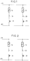
- Figure 1 illustrates very schematically such a command. As visible in this figure, it includes two control coils, a 1A to open the circuit breaker when energized, the other 1B to close the circuit breaker when powered, each connected in series with an end switch 2A, 2B and a local control push button 3A, 3B.
- Each switch 2A, 2B is linked to the mechanical movement of the circuit breaker. In position of the circuit breaker, one of the switches like 2A is closed and the other 2B is open. If the button 3A is pressed, the coil 1A is energized since the switch 2A is closed, which controls for example a solenoid valve and the circuit breaker sets in motion - a pole of the circuit breaker moves in its open position.
- FIG. 1 very schematically illustrates the control in the open position of the circuit breaker.
- To close the circuit breaker press the button 3B which excites coil 1B.
- the circuit breaker starts to move and comes to the closing.
- the switch 2B opens while the switch 2A closes and we found with the command in the state shown in Figure 1.
- the limit switches associated with the moving parts of the circuit breaker are very important.
- the coils of ordered To speed up the movement of these circuit breakers, the coils of ordered. But in return, we must have a time of over-excitation of very short control coils and so we only need the end switches of stroke of the control linked to the movement of the circuit breaker change state (open or closed) very quickly.
- circuit breaker failures are due to a malfunction of the auxiliary switches. in particular limit switches.
- the circuit breaker remains closed for a relatively long time.
- the limit switches tend to oxidize and thereby exhibiting an abnormally high contact resistance. It follows a malfunction of the circuit breaker in the presence of a short circuit and serious consequences for the maintenance of the electrical network in which is mounted this circuit breaker.
- FIG. 3 illustrates a diagram of such a command.
- each control coil is connected in series with a static limit switch 2A 'and 2B'.
- These static switches are controlled from a microcontroller 4 which receives representative signals the position of the circuit breaker and produced by position sensors 5A and 5B, the type magnetic sensors for example, which allows testing at any time the operating status of the static switches, whatever the position of the circuit breaker.
- the object of the invention is to propose a static switch at the end of race with high availability and completely testable at any time whatever the position of the circuit breaker.
- Another object of the invention is to propose an order for circuit breaker including such a switch protected against short-circuiting one or two control coils.
- the invention relates to a static switch at the end of travel for a circuit breaker control, characterized in that it comprises two transistors connected in series in a supply circuit of a coil circuit breaker control, and selectively controlled to close or open this supply circuit, a detection means mounted as a bypass at the terminals of first and second transistors to detect a conduction state or not conduction of both of said first and second transistors for the purposes of perform a test of their proper functioning and, a third transistor mounted in series with the detection means in order to carry out a good test operation of the detection means.
- the invention extends to a circuit breaker control including such a static limit switch and a protection system the static switch against a short-circuiting of the coil ordered.
- this protection system comprising a protection coil connected in series between the control coil and the switch, inductance well lower than the inductance of the control coil, and a circuit mounted at protective coil terminals capable of detecting that the voltage level at terminals of this protective coil is greater than a threshold corresponding to the short-circuiting the control coil and forcing the opening of a switch transistor to put it in a non-conduction state so to open the power supply circuit of the control coil.
- Figure 1 very schematically illustrates a circuit breaker control in a closed position.
- Figure 2 illustrates the circuit breaker control of Figure 1 in position circuit breaker opening.
- Figure 3 illustrates circuit breaker control with switches limit switches and a micro-controller.
- Figure 4 illustrates a first embodiment of a switch static limit switch according to the invention.
- Figure 5 illustrates a second embodiment of a switch static limit switch according to the invention.
- Figure 6 illustrates a third embodiment of a switch static limit switch according to the invention.
- Figure 7 illustrates the static limit switch in Figure 4 with a protection system against short-circuiting of a coil ordered.
- a static limit switch for control circuit breaker like switch 2A ', but with a high level of availability and completely testable, includes two transistors T1, T2 connected in series in the electrical circuit supplying a control coil, in the case of example the coil 1A, which on receipt of respective electrical signals C1 and C2 conducts or does not conduct current in this circuit.
- the switch also includes, in the embodiment of Figure 4, two sensors voltage D1, D2 mounted respectively in shunt at the terminals of the transistors T1 and T2 and which respectively provide verification signals V1 and V2 to the microcontroller 4 representative of the closed or open state of the transistors T1 and T2. It should be understood that these verification signals V1 and V2 are produced in response to control signals C1 and C2 and are used for implementation a self-diagnostic sequence of the switch by the microcontroller 4 when the circuit breaker is in standby state.
- the static limit switch 2A comprises a third transistor T3 connected in series with the two detectors D1 and D2 for cut off, when it is open the supply of these.
- both signals C1 and C2 at a certain voltage level are applied simultaneously on transistors T1 and T2 to make them conductive so that the coil 1A control unit is powered or to make them non-conductive so that cut the power supply to the control coil 1A.
- the structure of the static limit switch with the transistor auxiliary T3 and detectors D1 and D2 allows in addition, as will appear thereafter. to carry out a test sequence to guarantee 100% the switch availability.
- the test is carried out through a program executed by the microcontroller 4. This test can be triggered periodically.
- C1 +, C2 +, C3 + symbolize control signals which force the transistors T1, T2, T3 respectively to go into a conduction state (closed position) and C1-, C2-, C3- symbolize inactive control signals in response to which the transistors T1, T2, T3 respectively remain in the state of non-conduction (open position).
- V1 +, V2 + symbolize signals of verification V1 and V2 respectively representative of a voltage presence at the terminals respectively of transistors T1 and T2 and V1-, V2- symbolize verification signals Vi and V2 respectively representative of the absence of voltage at the terminals of transistors T1 and T2 respectively.
- detectors D1 and D2 are subjected to half the voltage + TV and produce the signals V1 + and V2 + respectively.
- the microcontroller 4 sends a control signal C1 + to the transistor T1
- the latter becomes saturated, the voltage across it disappears and therefore the detector D1 is subjected to a zero voltage and produces the signal V1-.
- Detector D2 is him subjected to a voltage + TV and produces the signal V2 +. Therefore, in this arrangement it is necessary that each detector D1 or D2 encode the signal V1 or V2 with the same logic value when it detects the presence of a + TV voltage and when it detects the presence of + TV / 2 voltage.
- auxiliary transistor T3 gives the switch static according to the invention 100% testability since any failure, either of an element of the control chain C1, C2, C3, or of an element of the verification chain D1, D2, T3, or one of the circuit switching elements main 1A, T1, T2 can be detected by the microcontroller 4.
- the detectors D1 and D2 are advantageously constituted by the association of a constant current source, connected in series with a photocoupler: this arrangement allows encoding correct signals V1 and V2 in the required voltage ranges, on the one hand, and on the other hand, allows the coded information to be transmitted to the microcontroller 4 via optical fibers, thus ensuring galvanic isolation of these informations.
- the same arrangement is advantageous for the transmission of commands C1, C2 and C3.
- FIG. 6 shows yet another embodiment of the static switch according to the invention in which, compared to that shown on FIG. 5, the transistor T2 is replaced by a pair of thyristors T2 ′ and T2 "and of an auxiliary MOS transistor T1 controlled respectively by signals of control C2 'and C2 ". one of the thyristors being used for the opening and the other for closing the coil supply circuit.
- This arrangement allows to switch strong powers.
- the interruption of the supply circuit of the control coil is carried out first via the thyristors and then by transistor T1.
- closing the supply circuit of the coil is carried out first via the transistor T1 then by through the thyristors.
- the transistor T1 opens and closes without current and allows the periodic test of the static switch by a sequence close to those described above.
- FIG. 7 part of a circuit breaker control is shown with a static switch 2A 'according to the invention mounted in series in the circuit supply of the control coil 1A for example and which is protected against a connection fault during maintenance of the circuit breaker, the switching directly on the voltage supplying the control coil 1A, that is to say when the control coil 1A is short-circuited.
- the coil 1A is supplied for example at a voltage + TV of 140 to 280 V and typically has the following characteristics: 0.1H and 100 ⁇ . As indicated above, a short circuit of the coil 1A on the switch 2A ' when the power supply of coil 1A is connected, by a abrupt rise in voltage and current to their maximum value within transistors T1 and T2 of switch 2A '. It is therefore necessary to detect the arrival of this short circuit and cut the power supply line of the front switch destruction of transistors.
- a similar protection circuit must be provided for the switch 2B '.
- This protection circuit first comprises a protection coil 10 connected in series between the control coil 1A and the static switch 2A '.
- This protection circuit first comprises a protection coil 10 connected in series between the control coil 1A and the static switch 2A '.
- the coil 10 which is seen apply all the voltage + TV when switching on the power supply. Therefore, there will have little or no voltage across the transistors T1 and T2.
- the protection coil 10 is produced using a ferrite core by example which has the advantage of having a magnetic permeability relative very stable pet high for weak coercive fields, this relative permeability suddenly passing to 1 at saturation.
- the reel of protection must be dimensioned so as not to saturate for the current to be cut by the switch. It therefore limits the current in the switch to a value weak in the first micro-seconds following the establishment of the short circuit.
- Detection of a short-circuiting of the control coil 1A is made by electronics 11 mounted across the protection coil 10.
- This electronics includes as visible in FIG. 7 an RC circuit having typically a time constant of around 10 ⁇ s.
- This RC circuit filters the high frequency signals generated during switching by the capacitors noise from the coils.
- the signal produced by the RC circuit is clipped by a Zener Z diode to produce a logic signal which attacks a bi-stable rocker BS memorizing the successive states of the control coil 1A.
- the electronics 11 are galvanically isolated from the coil of protection 10 if this constitutes the primary of a transformer, the secondary being made up of a winding of a few turns to reduce the tension to measure electronically at a few volts at the time of the short circuit.
- a bi-stable rocker BS is interposed between the command Ci and the transistor T1 and between the command C2 and the transistor T2 to open transistors T1 and T2 simultaneously in the event of detection of a high voltage corresponding to a short circuit at the terminals of the protection coil 10.
- the short circuit state of the control coil 1A is produced on an output A of one of the flip-flops BS which can be connected to the microcontroller 4.
- this protection circuit 11 of the transistors of the switch static according to the invention operates in the very first micro-seconds succeeding the short circuit, and therefore the transistors T1 and T2 then open that the current passing through them has a low value, generally lower than their nominal current of the order of 2.5A.
Landscapes
- Electronic Switches (AREA)
- Driving Mechanisms And Operating Circuits Of Arc-Extinguishing High-Tension Switches (AREA)
- Keying Circuit Devices (AREA)
- Emergency Protection Circuit Devices (AREA)
Applications Claiming Priority (2)
| Application Number | Priority Date | Filing Date | Title |
|---|---|---|---|
| FR9713768A FR2770679B1 (fr) | 1997-11-03 | 1997-11-03 | Interrupteur statique de fin de course pour commande de disjoncteur |
| FR9713768 | 1997-11-03 |
Publications (2)
| Publication Number | Publication Date |
|---|---|
| EP0913938A1 true EP0913938A1 (de) | 1999-05-06 |
| EP0913938B1 EP0913938B1 (de) | 2004-01-02 |
Family
ID=9512950
Family Applications (1)
| Application Number | Title | Priority Date | Filing Date |
|---|---|---|---|
| EP98402675A Expired - Lifetime EP0913938B1 (de) | 1997-11-03 | 1998-10-27 | Statischer Endschalter zur Betätigung eines Leistungsschalters |
Country Status (4)
| Country | Link |
|---|---|
| EP (1) | EP0913938B1 (de) |
| AT (1) | ATE257292T1 (de) |
| DE (1) | DE69820837T2 (de) |
| FR (1) | FR2770679B1 (de) |
Cited By (2)
| Publication number | Priority date | Publication date | Assignee | Title |
|---|---|---|---|---|
| EP2045683A1 (de) | 2007-10-05 | 2009-04-08 | Phoenix Contact GmbH & Co. KG | Vorrichtung und Verfahren zur Überprüfung von im Lastkreis einer sicherheitstechnischen Ausgangsschaltung redundant angeschalteten Aktoren |
| ES2548916R1 (es) * | 2012-09-19 | 2015-12-01 | Schweitzer Engineering Laboratories, Inc. | Contacto de alta velocidad capaz de detectar, indicar y evitar maniobras incorrectas debido a un fallo interno |
Families Citing this family (1)
| Publication number | Priority date | Publication date | Assignee | Title |
|---|---|---|---|---|
| DE102006030448B4 (de) * | 2006-06-29 | 2022-08-18 | Phoenix Contact Gmbh & Co. Kg | Sichere Ausgangsschaltung mit einem einkanaligen Peripherieanschluss für den Ausgang eines Bus-Teilnehmers |
Citations (4)
| Publication number | Priority date | Publication date | Assignee | Title |
|---|---|---|---|---|
| DE2407989A1 (de) * | 1974-02-20 | 1975-08-28 | Festo Maschf Stoll G | Arbeitszylinder fuer pneumatische oder hydraulische druckmedien |
| EP0574300A1 (de) * | 1992-06-09 | 1993-12-15 | Gec Alsthom T Et D Sa | Steuerungs- und Selbstüberwachungssystem, insbesondere für ein multipolares Gerät wie einen Hochspannungsschalter |
| EP0609158A1 (de) * | 1993-01-29 | 1994-08-03 | Schneider Electric Sa | Sicherheitsleistungsschnittstelle |
| EP0797010A2 (de) * | 1996-03-21 | 1997-09-24 | Nikko Electric Industry Co., Ltd. | Hydraulische Krafteinheit |
-
1997
- 1997-11-03 FR FR9713768A patent/FR2770679B1/fr not_active Expired - Fee Related
-
1998
- 1998-10-27 EP EP98402675A patent/EP0913938B1/de not_active Expired - Lifetime
- 1998-10-27 DE DE69820837T patent/DE69820837T2/de not_active Expired - Lifetime
- 1998-10-27 AT AT98402675T patent/ATE257292T1/de not_active IP Right Cessation
Patent Citations (4)
| Publication number | Priority date | Publication date | Assignee | Title |
|---|---|---|---|---|
| DE2407989A1 (de) * | 1974-02-20 | 1975-08-28 | Festo Maschf Stoll G | Arbeitszylinder fuer pneumatische oder hydraulische druckmedien |
| EP0574300A1 (de) * | 1992-06-09 | 1993-12-15 | Gec Alsthom T Et D Sa | Steuerungs- und Selbstüberwachungssystem, insbesondere für ein multipolares Gerät wie einen Hochspannungsschalter |
| EP0609158A1 (de) * | 1993-01-29 | 1994-08-03 | Schneider Electric Sa | Sicherheitsleistungsschnittstelle |
| EP0797010A2 (de) * | 1996-03-21 | 1997-09-24 | Nikko Electric Industry Co., Ltd. | Hydraulische Krafteinheit |
Cited By (3)
| Publication number | Priority date | Publication date | Assignee | Title |
|---|---|---|---|---|
| EP2045683A1 (de) | 2007-10-05 | 2009-04-08 | Phoenix Contact GmbH & Co. KG | Vorrichtung und Verfahren zur Überprüfung von im Lastkreis einer sicherheitstechnischen Ausgangsschaltung redundant angeschalteten Aktoren |
| US8138765B2 (en) | 2007-10-05 | 2012-03-20 | Phoenix Contact Gmbh & Co. Kg | Device and method for actuator monitoring of a safety-related load circuit connected with two channels |
| ES2548916R1 (es) * | 2012-09-19 | 2015-12-01 | Schweitzer Engineering Laboratories, Inc. | Contacto de alta velocidad capaz de detectar, indicar y evitar maniobras incorrectas debido a un fallo interno |
Also Published As
| Publication number | Publication date |
|---|---|
| DE69820837T2 (de) | 2004-11-04 |
| DE69820837D1 (de) | 2004-02-05 |
| EP0913938B1 (de) | 2004-01-02 |
| FR2770679A1 (fr) | 1999-05-07 |
| FR2770679B1 (fr) | 1999-12-31 |
| ATE257292T1 (de) | 2004-01-15 |
Similar Documents
| Publication | Publication Date | Title |
|---|---|---|
| EP1009006B1 (de) | Standardeinrichtung zur Steuerung eines Elektromagneten zum Öffnen oder Schliessen eines Schutzschalters | |
| FR2568425A1 (fr) | Circuit de coupure de courant en cas de defaut a la terre, avec protection contre l'interruption des conducteurs de neutre et de terre. | |
| FR2738664A1 (fr) | Dispositif hybride utilisant l'effet miller pour la protection des contacts electriques contre la formation d'arcs | |
| WO1996028872A1 (fr) | Appareil electrique de protection differentielle a circuit test | |
| EP0019507B1 (de) | Verbesserung kapazitiver Spannungstransformatoren mit elektronischem Ausgang | |
| FR2798506A1 (fr) | Actionneur electromagnetique muni de deux ressorts de rappel | |
| EP0204624B1 (de) | Einrichtung zur Überwachung des Zustands eines elektrischen Schalters und Anwendung in einem elektrischen Relais | |
| EP2899343B1 (de) | Vorrichtung zur Aufhebung der magnetischen Remanenz für elektromagnetische Schlösser | |
| EP0913938B1 (de) | Statischer Endschalter zur Betätigung eines Leistungsschalters | |
| CA2250348A1 (fr) | Dispositif de commande pour appareil contacteur-disjoncteur | |
| FR2755532A1 (fr) | Transformateur de courant, declencheur et disjoncteur comportant un tel transformateur | |
| FR2601811A1 (fr) | Circuit de commande pour la bobine excitatrice d'un electro-aimant | |
| FR2540685A1 (fr) | Interface pour relier un systeme informatique a un dispositif actionneur | |
| FR2747864A1 (fr) | Relais statique avec detection d'etat | |
| EP0150524A1 (de) | Anordnung für eine zeitlich definierte Leitungsunterbrechung durch eine Fernsprechteilnehmerstelle | |
| FR2735275A1 (fr) | Dispositif de verrouillage electrique de securite | |
| FR2792766A1 (fr) | Dispositif de detection pour commutation de charges electriques | |
| EP1320164A1 (de) | Differentialauslöser mit Prüfkreis | |
| EP4139946B1 (de) | Leitungsschutzschalter mit elektronischer auslösesteuerung | |
| EP0163349B1 (de) | Speiseschaltung für einen elektromagnetischen Kontaktgeber | |
| FR2989512A1 (fr) | Ensemble de commande d'une coupure d'une ligne en cas de surintensite dans cette ligne et disjoncteur de protection contre une surintensite dans une ligne | |
| FR2758411A1 (fr) | Appareil contacteur-disjoncteur | |
| WO2020240097A1 (fr) | Appareil de protection de ligne (l) electrique pour détecter un défaut de fuite, de court-circuit, de surintensité et d'arc | |
| EP1629598B1 (de) | Statische sichere ausgabestufe | |
| EP0813283B1 (de) | Gegen unbeabsichtigtes Auslösen immunisiertes Differentialschutz |
Legal Events
| Date | Code | Title | Description |
|---|---|---|---|
| PUAI | Public reference made under article 153(3) epc to a published international application that has entered the european phase |
Free format text: ORIGINAL CODE: 0009012 |
|
| AK | Designated contracting states |
Kind code of ref document: A1 Designated state(s): AT CH DE ES GB IT LI SE |
|
| AX | Request for extension of the european patent |
Free format text: AL;LT;LV;MK;RO;SI |
|
| 17P | Request for examination filed |
Effective date: 19991108 |
|
| AKX | Designation fees paid |
Free format text: AT CH DE ES GB IT LI SE |
|
| GRAH | Despatch of communication of intention to grant a patent |
Free format text: ORIGINAL CODE: EPIDOS IGRA |
|
| GRAS | Grant fee paid |
Free format text: ORIGINAL CODE: EPIDOSNIGR3 |
|
| GRAA | (expected) grant |
Free format text: ORIGINAL CODE: 0009210 |
|
| RAP1 | Party data changed (applicant data changed or rights of an application transferred) |
Owner name: ALSTOM T & D SA |
|
| AK | Designated contracting states |
Kind code of ref document: B1 Designated state(s): AT CH DE ES GB IT LI SE |
|
| REG | Reference to a national code |
Ref country code: GB Ref legal event code: FG4D Free format text: NOT ENGLISH |
|
| REG | Reference to a national code |
Ref country code: CH Ref legal event code: EP |
|
| REF | Corresponds to: |
Ref document number: 69820837 Country of ref document: DE Date of ref document: 20040205 Kind code of ref document: P |
|
| REG | Reference to a national code |
Ref country code: SE Ref legal event code: TRGR |
|
| PG25 | Lapsed in a contracting state [announced via postgrant information from national office to epo] |
Ref country code: ES Free format text: LAPSE BECAUSE OF FAILURE TO SUBMIT A TRANSLATION OF THE DESCRIPTION OR TO PAY THE FEE WITHIN THE PRESCRIBED TIME-LIMIT Effective date: 20040413 |
|
| GBT | Gb: translation of ep patent filed (gb section 77(6)(a)/1977) |
Effective date: 20040324 |
|
| PGFP | Annual fee paid to national office [announced via postgrant information from national office to epo] |
Ref country code: AT Payment date: 20041013 Year of fee payment: 7 |
|
| PLBE | No opposition filed within time limit |
Free format text: ORIGINAL CODE: 0009261 |
|
| STAA | Information on the status of an ep patent application or granted ep patent |
Free format text: STATUS: NO OPPOSITION FILED WITHIN TIME LIMIT |
|
| 26N | No opposition filed |
Effective date: 20041005 |
|
| REG | Reference to a national code |
Ref country code: CH Ref legal event code: PFA Owner name: AREVA T & D SA Free format text: ALSTOM T & D SA#25 AVENUE KLEBER#75116 PARIS (FR) -TRANSFER TO- AREVA T & D SA#1, PLACE DE LA COUPOLE TOUR AREVA#92084 PARIS LA DEFENSE (FR) |
|
| PG25 | Lapsed in a contracting state [announced via postgrant information from national office to epo] |
Ref country code: AT Free format text: LAPSE BECAUSE OF NON-PAYMENT OF DUE FEES Effective date: 20051027 |
|
| REG | Reference to a national code |
Ref country code: DE Ref legal event code: R082 Ref document number: 69820837 Country of ref document: DE Representative=s name: GRUENECKER, KINKELDEY, STOCKMAIR & SCHWANHAEUS, DE |
|
| REG | Reference to a national code |
Ref country code: DE Ref legal event code: R082 Ref document number: 69820837 Country of ref document: DE Representative=s name: GRUENECKER PATENT- UND RECHTSANWAELTE PARTG MB, DE Effective date: 20121211 Ref country code: DE Ref legal event code: R082 Ref document number: 69820837 Country of ref document: DE Representative=s name: GRUENECKER, KINKELDEY, STOCKMAIR & SCHWANHAEUS, DE Effective date: 20121211 Ref country code: DE Ref legal event code: R081 Ref document number: 69820837 Country of ref document: DE Owner name: ALSTOM GRID SAS, FR Free format text: FORMER OWNER: AREVA T&D SA, PARIS, FR Effective date: 20121211 Ref country code: DE Ref legal event code: R081 Ref document number: 69820837 Country of ref document: DE Owner name: ALSTOM TECHNOLOGY LTD., CH Free format text: FORMER OWNER: AREVA T&D SA, PARIS, FR Effective date: 20121211 |
|
| REG | Reference to a national code |
Ref country code: DE Ref legal event code: R082 Ref document number: 69820837 Country of ref document: DE Representative=s name: GRUENECKER, KINKELDEY, STOCKMAIR & SCHWANHAEUS, DE |
|
| REG | Reference to a national code |
Ref country code: DE Ref legal event code: R082 Ref document number: 69820837 Country of ref document: DE Representative=s name: GRUENECKER PATENT- UND RECHTSANWAELTE PARTG MB, DE Effective date: 20130610 Ref country code: DE Ref legal event code: R082 Ref document number: 69820837 Country of ref document: DE Representative=s name: GRUENECKER, KINKELDEY, STOCKMAIR & SCHWANHAEUS, DE Effective date: 20130610 Ref country code: DE Ref legal event code: R081 Ref document number: 69820837 Country of ref document: DE Owner name: ALSTOM TECHNOLOGY LTD., CH Free format text: FORMER OWNER: ALSTOM GRID SAS, PARIS, FR Effective date: 20130610 |
|
| REG | Reference to a national code |
Ref country code: CH Ref legal event code: PUE Owner name: ALSTOM TECHNOLOGY LTD, CH Free format text: FORMER OWNER: AREVA T AND D SA, FR |
|
| REG | Reference to a national code |
Ref country code: GB Ref legal event code: 732E Free format text: REGISTERED BETWEEN 20130815 AND 20130821 |
|
| PGFP | Annual fee paid to national office [announced via postgrant information from national office to epo] |
Ref country code: GB Payment date: 20131010 Year of fee payment: 16 |
|
| GBPC | Gb: european patent ceased through non-payment of renewal fee |
Effective date: 20141027 |
|
| PG25 | Lapsed in a contracting state [announced via postgrant information from national office to epo] |
Ref country code: GB Free format text: LAPSE BECAUSE OF NON-PAYMENT OF DUE FEES Effective date: 20141027 |
|
| PGFP | Annual fee paid to national office [announced via postgrant information from national office to epo] |
Ref country code: IT Payment date: 20151014 Year of fee payment: 18 Ref country code: CH Payment date: 20151007 Year of fee payment: 18 Ref country code: DE Payment date: 20151014 Year of fee payment: 18 |
|
| PGFP | Annual fee paid to national office [announced via postgrant information from national office to epo] |
Ref country code: SE Payment date: 20151014 Year of fee payment: 18 |
|
| REG | Reference to a national code |
Ref country code: DE Ref legal event code: R119 Ref document number: 69820837 Country of ref document: DE |
|
| REG | Reference to a national code |
Ref country code: CH Ref legal event code: PL |
|
| PG25 | Lapsed in a contracting state [announced via postgrant information from national office to epo] |
Ref country code: LI Free format text: LAPSE BECAUSE OF NON-PAYMENT OF DUE FEES Effective date: 20161031 Ref country code: DE Free format text: LAPSE BECAUSE OF NON-PAYMENT OF DUE FEES Effective date: 20170503 Ref country code: CH Free format text: LAPSE BECAUSE OF NON-PAYMENT OF DUE FEES Effective date: 20161031 |
|
| PG25 | Lapsed in a contracting state [announced via postgrant information from national office to epo] |
Ref country code: SE Free format text: LAPSE BECAUSE OF NON-PAYMENT OF DUE FEES Effective date: 20161028 |
|
| PG25 | Lapsed in a contracting state [announced via postgrant information from national office to epo] |
Ref country code: IT Free format text: LAPSE BECAUSE OF NON-PAYMENT OF DUE FEES Effective date: 20161027 |