EP0914904A2 - Polieraufschlämmungspender - Google Patents
Polieraufschlämmungspender Download PDFInfo
- Publication number
- EP0914904A2 EP0914904A2 EP98309026A EP98309026A EP0914904A2 EP 0914904 A2 EP0914904 A2 EP 0914904A2 EP 98309026 A EP98309026 A EP 98309026A EP 98309026 A EP98309026 A EP 98309026A EP 0914904 A2 EP0914904 A2 EP 0914904A2
- Authority
- EP
- European Patent Office
- Prior art keywords
- slurry
- housing
- dispenser
- slurry dispenser
- wheel assembly
- Prior art date
- Legal status (The legal status is an assumption and is not a legal conclusion. Google has not performed a legal analysis and makes no representation as to the accuracy of the status listed.)
- Withdrawn
Links
Images



Classifications
-
- B—PERFORMING OPERATIONS; TRANSPORTING
- B24—GRINDING; POLISHING
- B24B—MACHINES, DEVICES, OR PROCESSES FOR GRINDING OR POLISHING; DRESSING OR CONDITIONING OF ABRADING SURFACES; FEEDING OF GRINDING, POLISHING, OR LAPPING AGENTS
- B24B37/00—Lapping machines or devices; Accessories
- B24B37/04—Lapping machines or devices; Accessories designed for working plane surfaces
-
- B—PERFORMING OPERATIONS; TRANSPORTING
- B24—GRINDING; POLISHING
- B24B—MACHINES, DEVICES, OR PROCESSES FOR GRINDING OR POLISHING; DRESSING OR CONDITIONING OF ABRADING SURFACES; FEEDING OF GRINDING, POLISHING, OR LAPPING AGENTS
- B24B57/00—Devices for feeding, applying, grading or recovering grinding, polishing or lapping agents
- B24B57/02—Devices for feeding, applying, grading or recovering grinding, polishing or lapping agents for feeding of fluid, sprayed, pulverised, or liquefied grinding, polishing or lapping agents
-
- H—ELECTRICITY
- H10—SEMICONDUCTOR DEVICES; ELECTRIC SOLID-STATE DEVICES NOT OTHERWISE PROVIDED FOR
- H10P—GENERIC PROCESSES OR APPARATUS FOR THE MANUFACTURE OR TREATMENT OF DEVICES COVERED BY CLASS H10
- H10P50/00—Etching of wafers, substrates or parts of devices
Definitions
- the present invention relates to dispensing a liquid.
- the present invention relates to dispensing slurry in a chemical-mechanical polishing (CMP) application.
- CMP chemical-mechanical polishing
- CMP techniques are used to create the planarity required in multi-level interconnect structures.
- an interlayer dielectric e.g., silicon dioxide
- an interlayer dielectric e.g., silicon dioxide
- a polishing process which uses an alkaline or acidic slurry with fine abrasive.
- an alkaline or acidic slurry includes fine silicon dioxide particles (e.g., average diameter of 70 nm) suspended in deionized water having an adjusted pH of approximately 11.
- the alkalinity can be provided by potassium hydroxide (KOH) and ammonium hydroxide (NH 3 OH).
- KOH potassium hydroxide
- NH 3 OH ammonium hydroxide
- the semiconductor wafer to be polished is held under slight pressure by a polishing head against a polishing pad.
- the polishing pad is typically made of a polyurethrane material.
- the polishing head moves the semiconductor wafer according to a predetermined motion pattern.
- the polishing pad can be mounted on a platform which moves relative to the semiconductor wafer. The motion of the semiconductor wafer relative to the polishing pad and the mechanical and chemical actions of the slurry, together provide a polishing action for planarizing the surface of the wafer.
- the slurry has a high content of water, the slurry is not only an abrasive, but also acts as a coolant which maintains the surface of the wafer to an acceptable temperature.
- the slurry is typically sprayed onto the surface of the polishing pad by appropriately positioned nozzles linked by a slurry supply line, and delivered to the surface of the polishing pad at 50 to 500 cc per minute using a peristalic pump.
- deposits from the slurry can clog the nozzles, leading to uneven and inadequate delivery.
- uneven and inadequate slurry delivery can result in poor polishing uniformity and even severe damage to the wafer due to excessive heat.
- even when nozzles are in good working condition it is difficult to control the amount of slurry that is dispensed.
- a slurry dispenser which dispenses slurry from a rotating wheel is provided.
- the slurry dispenser includes: (a) a housing having an opening; (b) a reservoir provided inside the housing for holding the slurry; (c) a rotating mechanism, such as a motor, and (d) a wheel assembly provided within the housing and engaged to rotate with said rotational mechanism.
- the wheel assembly includes a conical member inserted into the slurry reservoir and a disk portion.
- a stream of slurry is forced up a side wall of the conical member of the wheel assembly, so that the slurry is dispensed as a spray by the disk through the opening of the housing.
- the spray is created by a centrifugal force resulting from the rotation.
- a variable speed DC motor is used, the amount of slurry dispensed by the slurry dispenser can be controlled by an applied voltage to the motor.
- the housing, the wheels and any surface that comes into contact with the slurry can be constructed from a synthetic material (e.g., polycarbonate, polypropylene, polyvinylidene fluoride (PVDF), or any material with a teflon coating on exposed surfaces) which is chemically inert with respect to the slurry.
- a synthetic material e.g., polycarbonate, polypropylene, polyvinylidene fluoride (PVDF), or any material with a teflon coating on exposed surfaces
- PVDF polyvinylidene fluoride
- the housing of the slurry dispenser includes wall portions in the proximity of the opening, such that the slurry spray is restricted to a predetermined angle.
- An inlet is provided in the slurry dispenser for attaching a slurry supply line to maintain a continuous supply of slurry into the slurry reservoir of the slurry dispenser.
- a self-cleaning slurry dispenser which dispenses slurry from two counter-rotating wheels is also provided.
- the slurry dispenser includes: (a) a housing having two openings; (b) two reservoirs provided inside the housing for holding the slurry; (c) two rotating mechanisms, and (d) two wheels provided within the housing and engaged to rotate with said rotating mechanisms.
- the rotating mechanisms turn the wheels in opposite directions, providing an overlapping spray of slurry.
- the shape of the openings in the housing restricts the slurry spray to a predetermined angle.
- the slurry dispenser includes a sliding door operated by an air cylinder and an inlet for cleaning water such that when the sliding door is closed the housing can be washed without operator intervention and without cross contamination between the interior and the exterior of the housing.
- the slurry dispensers of the present invention allow even distribution of slurry across the polishing pad and fine control of the amount of slurry dispensed, so that waste of slurry is minimized. Furthermore, a self-cleaning slurry dispenser is provided.
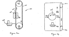
- FIGS 1a and 1b show, respectively, schematic front and side views of a CMP apparatus 100, including a slurry dispenser 104, in accordance with the present invention.
- Figure 2a shows an assembled side view of slurry dispenser 104.
- Figure 2b shows an "exploded" side view of slurry dispenser 104.
- Figure 3a shows a front view of slurry dispenser 104.
- Figure 3b illustrates the operation of slurry dispenser 104.
- Figure 4 illustrates the operation of slurry dispenser 104 using a vertical sectional view of slurry dispenser 104.
- Figure 5 shows a front isometric view of slurry dispenser 124.
- Figure 6a shows a back isometric view of slurry dispenser 124.
- Figure 6b shows an "exploded" back view of slurry dispenser 124.
- Figure 7 shows wheel 250.
- Figure 8 shows a top view of wheel housing with the wheels removed to reveal the reservoirs 248.
- Figure 9 illustrates the operation of slurry dispenser 124 using a view from the top of the interior of wheel housing 240.
- Figures 10 and 1b show, respectively, vertical and horizontal sectional views of slurry dispenser 500, in accordance with the present invention.
- the present invention provides a slurry dispenser free of the problems of the prior art described in the previous section.
- like elements in the figures are provided like reference numerals.
- FIGS la and 1b show CMP apparatus 100 in side and front views, respectively.
- CMP apparatus 100 includes a continuous polishing belt 101 configured to polish one or more vertically held semiconductor wafers, such as wafer 107.
- Wafer 107 is held vertically by a polishing head 105, which presses wafer 107 against a polishing pad attached to a vertically mounted polishing belt 101.
- Polishing belt 101 is kept in continuous motion by rotating pulleys 102 and 103 at a selected polishing speed (e.g., 10 meters per second).
- a support assembly 106 provides a backward pressure to hold wafer 107 at a preselected pressure (e.g., 5 psi) against polishing belt 101.
- Polishing head 105 rotates in a predetermined direction indicated by reference numeral 109 and is optionally moved back and forth across the polishing pad surface in straight lines indicated by reference numerals 107a and 107b. While Figure 1 shows only one side of the polishing belt assembly being used for wafer polishing, polishing heads and accompanying mechanisms can be provided on both sides of the polishing belt assembly of CMP apparatus 100 to increase the total wafer throughput.
- the present invention provides a slurry dispenser 104, which is positioned at a short distance upstream (relative to polishing belt 101's direction of travel) from polishing head 105.
- Slurry dispenser 104 sprays a fine stream of slurry from a rapidly rotating wheel.
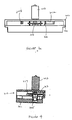
- Figure 2a provides an assembled side view of slurry dispenser 104.
- slurry dispenser 104 includes (a) a lower housing 201, including a slurry reservoir 205, (b) an upper housing 202, fastened to lower housing 201 by, for example, set screws, and (c) a variable speed motor 203.
- a component wheel assembly is enclosed between lower and upper housings 201 and 202.
- Upper housing 202 includes a slurry inlet 204, which is connected during operation to a slurry supply line (not shown) to provide slurry dispenser 104 a continuous supply of slurry.
- a peristolic pump can be used to provide the slurry in the supply line.
- upper and lower housings 202 and 201, and the component wheel assembly can be constructed out of polycarbonate, polypropylene, polyvinylidene fluoride (PVDF), any material with a teflon coating on exposed surfaces, or any other material inert to the slurry (e.g. a hard plastic).
- Motor 203 is preferably a DC motor which speed can be varied by varying the magnitude of an applied voltage.
- Upper housing 202 has an opening at the front (i.e., opening 310 shown in Figures 3a, 3b and 4 and described below), so that a spray of slurry can be provided through that opening.
- FIG. 2a shows an "exploded" side view of slurry dispenser 104.
- dispenser 104 in addition to motor 203, and upper and lower housings 201 and 202 (including slurry inlet 204 and slurry reservoir 205), dispenser 104 includes a wheel assembly 210, which has at least these members: (a) a linkage member 212, for engaging a rotating shaft 211 of motor 203, such that, during operation, wheel assembly 210 turns at the speed of motor 203, (b)a wheel or disk portion 213, including a groove 217 between its upper and lower surfaces, and (c) a conical member 214, attached to the lower surface of disk portion 213.
- Figure 2b also shows a set of through holes 216, through which set screws can be provided to fasten upper housing 202 to lower housing 201, engaging corresponding threaded holes in upper housing 202.
- Conical member 214 is inserted into opening 215 in lower housing 201. Opening 215 opens into slurry reservoir 205.
- a front view of slurry dispenser 104 is provided in Figure 3a, looking from the direction of front opening 310 in upper housing 202.
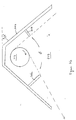
- two partial walls 301a and 301b are provided from the ceiling of upper housing 202. Partial walls 301a and 301b are provided to restrict the angle of the slurry spray from slurry dispenser 104.
- Figure 3b is a view of slurry dispenser 104 viewed from the ceiling of upper housing 202 and Figure 4 is a vertical sectional view of slurry dispenser 104.
- motor 203 turns wheel assembly 210 at a predetermined speed (e.g., 2000 to 3000 revolutions per minute).
- the desired operational speed of the motor is primarily determined by the amount of slurry required to be dispensed. Generally, a higher speed would dispense a greater amount of slurry. The actual speed required can be determined empirically.
- a stream of slurry is forced to creep up from slurry reservoir 205 along a side wall of conical member 214, due to the boundary layer created at the surface of conical member 214.
- This stream of slurry flow continues over the lower surface of disk portion 213 into groove 217.
- the centrifugal force of spinning wheel assembly 210 spray the slurry from groove 217 out of slurry dispenser 104 through opening 310 of upper housing 202.
- the sharp edges of disk portion 213, formed by the walls of groove 217, serve to restrict the spray to a thin layer in the vertical direction.
- the sloping sidewalls of conical member 214 are inclined 100 degrees from disk portion 213.
- walls 301a and 301b restrict the spray of slurry horizontally to the predetermined angle ⁇ shown.
- the magnitude of this angle, hence the length of walls 301a and 301b is determined empirically. Slurry that flows out of slurry dispenser 104 (e.g., slurry caught by the walls of the housings) can be collected and recycled to avoid waste.
- a slurry dispenser using two wheels is provided.
- Slurry dispenser 124 sprays a fine stream of slurry from a pair of rapidly counter-rotating wheels.
- Figure 5 provides an isometric view of the front of slurry dispenser 124.
- slurry dispenser 124 includes a front face 220 with openings 225 to the wheel housing 240 positioned behind the front face. Openings in wheel housing 240 align with the openings 225 in front face 220.
- the interior of wheel housing 240 contains two wheels 250, positioned above slurry reservoir slots 248 in the bottom face of the housing interior.
- Wheel housing 240 is connected to slurry inlet lines 340, which are connected during operation to slurry supply lines (not shown) to provide slurry dispenser 124 a continuous supply of slurry.
- a peristolic pump can be used to provide the slurry in the supply lines.
- a pair of variable speed motors 320 is positioned above wheel housing 240. Motors 320 are preferably DC motors. Motors 320 have a rotating shaft extending downward which fits into a slot 251 on the top of wheels 250, as illustrated in Figure 7.
- the bottom portion of wheels 250 is a conical portion 252.
- a disk portion 253 is positioned above the conical portion.
- slurry reservoir slots 248 at the bottom of wheel housing 240 are shown in Figure 8, which provides a top view of the wheel housing with the wheels removed.
- wheels 250 are placed such that the bottom point of the conical portion 252 is positioned at the center crossing points 249 of slurry reservoir slots 248.
- the design of slurry reservoir slots 248 advantageously minimizes the use of slurry.
- Figure 9 is a view of slurry dispenser 124 viewed from the ceiling of the interior of wheel housing 240.
- motors 203 turns wheels 250 in opposite directions 610 at a predetermined speed (e.g., 3000 to 6000 revolutions per minute) .
- a predetermined speed e.g. 3000 to 6000 revolutions per minute
- This provides an overlapping spray of slurry as indicated by slurry distribution arrows 620.
- the desired operational speed of the motor is primarily determined by the amount of slurry required to be dispensed and the desired distribution pattern. Generally, a higher speed would dispense a greater amount of slurry and provide greater overlap in the center of the distribution.
- a higher speed also results in a smaller droplet size, while a larger droplet size is desired to reduce misting.
- the preferred speed can be determined empirically as a tradeoff between flow rate and droplet size.
- a typical rate of supplying slurry through slurry supply lines 340 is approximately 450 ml/min.
- a stream of slurry is forced to creep up from slurry reservoir slots 248 along a side wall of the conical portion 252 of wheels 250, due to the boundary layer created at the surface of the conical portion.
- This stream of slurry flow continues over the lower surface of the disk portion 253 of wheels 250.
- the centrifugal force of spinning wheel 250 sprays the slurry out of slurry dispenser 104 through openings of wheel housing 240.
- the sharp edges of the disk portion of wheels 250 serve to restrict the spray to a thin layer in the vertical direction.
- the sloping sidewalls of conical portion 252 are inclined approximately 120 degrees from disk portion 253.
- the shape of opening 225 in front face 220 and the corresponding shape of the openings in wheel housing 240 determine the horizontal width of the slurry distribution.
- Wheel housing 240 and wheels 250 can be constructed out of polypropylene, polyvinylidene fluoride (PVDF), Kynar, any material with a teflon coating on exposed surfaces, or any other material inert to the slurry (e.g. a hard plastic). Fittings are typically teflon. Drains and supply lines, discussed below, are typically constructed of teflon or PVDF. All the corners of the interior of wheel housing 240 are rounded for ease of cleaning of slurry dispenser 124, as described below.
- Slurry dispenser 124 also includes a sliding door 230, which can be closed to permit washing of the interior of wheel housing 240.
- Sliding door 230 is operated by air cylinder 335 enclosed in air cylinder housing 235, shown in Figures 6a and 6b.
- Water for cleaning is supplied from water inlet lines 343.
- Wheel housing 240 is drained through slurry drain lines 242 which are connected to slurry drain valves 243. During typical operation, wheel housing 240 is washed between polishing of each wafer without operator intervention.
- Sliding door 230 also includes an attached pair of gutters 332.
- Gutters 332 are constructed of plastic with vinyl hinges. When sliding door 230 is closed, gutters 332 are folded inside and are washed by the water supplied from water inlet lines 343. When sliding door 230 is open, gutters 332 extend horizontally over openings 225 in front face 220, as shown in Figure 5, and protect the interior of wheel housing 240 from any liquid flowing down front face 220. During typical operation of slurry dispenser 124, water flows down front face 220. Sliding door 230 and gutter 332 advantageously allow the interior and exterior of wheel housing 240 to be washed without cross contamination. That is, slurry from inside wheel housing 240 is prevented from being washed onto the polishing pad attached to polishing belt 101, and exterior washing is prevented from diluting slurry inside wheel housing 240.
- a third embodiment of the present invention is suitable for use with a polishing apparatus in which the polishing belt is vertically mounted but travels in a horizontal direction.
- a polishing apparatus in which the polishing belt is vertically mounted but travels in a horizontal direction.
- rotating CMP apparatus 100 90 degrees in the plane of polishing pad 101.
- a rotating wheel in a slurry dispenser for such a polishing apparatus unlike the rotating wheel in slurry dispenser 104 of Figures la and 1b (which rotates in a horizontal plane), rotates in a vertical plane.
- the reservoir from which slurry are drawn cannot be provided in the same way as reservoir 205 of Figure 4.
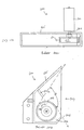
- Figures 10a and 10b show, respectively, vertical and horizontal sections through a slurry dispenser 500 suitable for implementing this third embodiment of the present invention.
- slurry dispenser 500 sprays a stream of slurry from an opening 507 on the side of housing 505.
- a component wheel assembly 503, which is housed within housing 505, is rotated by a shaft 504 coupled to a variable speed motor 502 located outside of housing 505.
- component wheel assembly 503 is partially immersed in a slurry reservoir 506 located at the bottom of housing 505, such that, when component wheel assembly 503 is rotated by shaft 504 in the direction indicated by reference numeral 503, slurry is carried by rotating component wheel assembly 503 and sprayed out of opening 507 of housing 505 by the centrifugal force.
- Partial wall 501a and side wall 501b of reservoir 506 serve to restrict the angle ⁇ of spray in substantially the same manner as partial walls 301a and 301b in slurry dispenser 104 of Figures 3a and 3b.
Landscapes
- Engineering & Computer Science (AREA)
- Mechanical Engineering (AREA)
- Mechanical Treatment Of Semiconductor (AREA)
- Finish Polishing, Edge Sharpening, And Grinding By Specific Grinding Devices (AREA)
- Feeding, Discharge, Calcimining, Fusing, And Gas-Generation Devices (AREA)
- Grinding-Machine Dressing And Accessory Apparatuses (AREA)
Applications Claiming Priority (4)
| Application Number | Priority Date | Filing Date | Title |
|---|---|---|---|
| US965067 | 1997-11-05 | ||
| US08/965,067 US5964413A (en) | 1997-11-05 | 1997-11-05 | Apparatus for dispensing slurry |
| US09/113,727 US6098901A (en) | 1997-11-05 | 1998-07-10 | Apparatus for dispensing slurry |
| US113727 | 1998-07-10 |
Publications (2)
| Publication Number | Publication Date |
|---|---|
| EP0914904A2 true EP0914904A2 (de) | 1999-05-12 |
| EP0914904A3 EP0914904A3 (de) | 2002-07-10 |
Family
ID=26811399
Family Applications (1)
| Application Number | Title | Priority Date | Filing Date |
|---|---|---|---|
| EP98309026A Withdrawn EP0914904A3 (de) | 1997-11-05 | 1998-11-04 | Polieraufschlämmungspender |
Country Status (6)
| Country | Link |
|---|---|
| US (1) | US6098901A (de) |
| EP (1) | EP0914904A3 (de) |
| JP (1) | JPH11216667A (de) |
| KR (1) | KR19990045034A (de) |
| CN (1) | CN1092544C (de) |
| TW (1) | TW380082B (de) |
Families Citing this family (6)
| Publication number | Priority date | Publication date | Assignee | Title |
|---|---|---|---|---|
| US8439723B2 (en) | 2008-08-11 | 2013-05-14 | Applied Materials, Inc. | Chemical mechanical polisher with heater and method |
| US20100041316A1 (en) * | 2008-08-14 | 2010-02-18 | Yulin Wang | Method for an improved chemical mechanical polishing system |
| US8414357B2 (en) | 2008-08-22 | 2013-04-09 | Applied Materials, Inc. | Chemical mechanical polisher having movable slurry dispensers and method |
| CN102380818A (zh) * | 2010-09-01 | 2012-03-21 | 无锡华润上华半导体有限公司 | 化学机械研磨方法和研磨设备 |
| KR102214510B1 (ko) | 2016-01-18 | 2021-02-09 | 삼성전자 주식회사 | 기판 씨닝 장치, 이를 이용한 기판의 씨닝 방법, 및 반도체 패키지의 제조 방법 |
| US20240383096A1 (en) * | 2023-05-16 | 2024-11-21 | Taiwan Semiconductor Manufacturing Co., Ltd. | Polish Apparatus and Methods for Use |
Family Cites Families (10)
| Publication number | Priority date | Publication date | Assignee | Title |
|---|---|---|---|---|
| US30963A (en) * | 1860-12-18 | Improvement in cultivators | ||
| US1535147A (en) * | 1920-06-09 | 1925-04-28 | Hydro Vacuum Elevator Company | Apparatus for lifting water, grain, or the like |
| US1488356A (en) * | 1921-05-10 | 1924-03-25 | Joseph Gemayel | Atomizer burner |
| US2537833A (en) * | 1946-09-12 | 1951-01-09 | Joos Bernhard | Apparatus for nebulizing liquids |
| US2783088A (en) * | 1953-11-09 | 1957-02-26 | Thomas P Butler | Minnow box aerator pump |
| US3346192A (en) * | 1963-12-18 | 1967-10-10 | Hege Hermann | Atomizing apparatus |
| DK124566B (da) | 1968-11-05 | 1972-10-30 | Niro Atomizer As | Forstøverhjul med slidfaste sintrede bøsninger. |
| GB1310912A (en) * | 1969-05-28 | 1973-03-21 | Ici Ltd | Spray device |
| US4553700A (en) * | 1984-03-19 | 1985-11-19 | Polaris Home Systems, Inc. | Centrifugal sprayer having hollow cone feeder |
| US5203506A (en) * | 1991-12-16 | 1993-04-20 | Product Development (Z.G.S.) Ltd. | Liquid pump and nebulizer constructed therewith |
-
1998
- 1998-07-10 US US09/113,727 patent/US6098901A/en not_active Expired - Lifetime
- 1998-11-04 JP JP31273298A patent/JPH11216667A/ja active Pending
- 1998-11-04 EP EP98309026A patent/EP0914904A3/de not_active Withdrawn
- 1998-11-05 CN CN98123943A patent/CN1092544C/zh not_active Expired - Fee Related
- 1998-11-05 KR KR1019980047309A patent/KR19990045034A/ko not_active Withdrawn
- 1998-11-19 TW TW087118375A patent/TW380082B/zh not_active IP Right Cessation
Also Published As
| Publication number | Publication date |
|---|---|
| JPH11216667A (ja) | 1999-08-10 |
| CN1223194A (zh) | 1999-07-21 |
| KR19990045034A (ko) | 1999-06-25 |
| EP0914904A3 (de) | 2002-07-10 |
| US6098901A (en) | 2000-08-08 |
| TW380082B (en) | 2000-01-21 |
| CN1092544C (zh) | 2002-10-16 |
Similar Documents
| Publication | Publication Date | Title |
|---|---|---|
| US5846336A (en) | Apparatus and method for conditioning a planarizing substrate used in mechanical and chemical-mechanical planarization of semiconductor wafers | |
| US5964413A (en) | Apparatus for dispensing slurry | |
| US6179693B1 (en) | In-situ/self-propelled polishing pad conditioner and cleaner | |
| US7997958B2 (en) | Apparatuses and methods for conditioning polishing pads used in polishing micro-device workpieces | |
| JP4693203B2 (ja) | ポリシングスラリーを供給するキャリヤヘッド | |
| US6022807A (en) | Method for fabricating an integrated circuit | |
| US5725417A (en) | Method and apparatus for conditioning polishing pads used in mechanical and chemical-mechanical planarization of substrates | |
| US6833046B2 (en) | Planarizing machines and methods for mechanical and/or chemical-mechanical planarization of microelectronic-device substrate assemblies | |
| US6283840B1 (en) | Cleaning and slurry distribution system assembly for use in chemical mechanical polishing apparatus | |
| US6722943B2 (en) | Planarizing machines and methods for dispensing planarizing solutions in the processing of microelectronic workpieces | |
| US6331136B1 (en) | CMP pad conditioner arrangement and method therefor | |
| US7021999B2 (en) | Rinse apparatus and method for wafer polisher | |
| US6302771B1 (en) | CMP pad conditioner arrangement and method therefor | |
| JPH09186118A (ja) | ケミカルメカニカルポリシングシステムのスラリ分散の装置及び方法 | |
| EP0914904A2 (de) | Polieraufschlämmungspender | |
| TW414968B (en) | Pad cleaning system of semiconductor device fabrication facility and cleaning method thereby | |
| US6896600B1 (en) | Liquid dispense manifold for chemical-mechanical polisher | |
| JP3240247B2 (ja) | 半導体装置の製造方法及び研磨装置 | |
| US6482290B1 (en) | Sweeping slurry dispenser for chemical mechanical polishing | |
| JP3708740B2 (ja) | 研磨装置および研磨方法 | |
| KR100445634B1 (ko) | 반도체 웨이퍼의 평탄화 설비 | |
| US12459080B2 (en) | Cleaning system for polishing liquid delivery arm | |
| US6929533B2 (en) | Methods for enhancing within-wafer CMP uniformity | |
| KR100567891B1 (ko) | 화학적 기계적 연마장치의 컨디셔너 | |
| US20260061557A1 (en) | Slurry delivery method |
Legal Events
| Date | Code | Title | Description |
|---|---|---|---|
| PUAI | Public reference made under article 153(3) epc to a published international application that has entered the european phase |
Free format text: ORIGINAL CODE: 0009012 |
|
| AK | Designated contracting states |
Kind code of ref document: A2 Designated state(s): AT BE CH CY DE DK ES FI FR GB GR IE IT LI LU MC NL PT SE |
|
| AX | Request for extension of the european patent |
Free format text: AL;LT;LV;MK;RO;SI |
|
| PUAL | Search report despatched |
Free format text: ORIGINAL CODE: 0009013 |
|
| RIC1 | Information provided on ipc code assigned before grant |
Free format text: 7B 24B 37/04 A, 7B 24B 57/02 B, 7B 05B 3/08 B, 7H 01L 21/304 - |
|
| AK | Designated contracting states |
Kind code of ref document: A3 Designated state(s): AT BE CH CY DE DK ES FI FR GB GR IE IT LI LU MC NL PT SE |
|
| AX | Request for extension of the european patent |
Free format text: AL;LT;LV;MK;RO;SI |
|
| STAA | Information on the status of an ep patent application or granted ep patent |
Free format text: STATUS: THE APPLICATION IS DEEMED TO BE WITHDRAWN |
|
| 18D | Application deemed to be withdrawn |
Effective date: 20020531 |