EP0914953B1 - Système de nettoyage d'interconnexion électrique pour cartouches à jet d'encre - Google Patents
Système de nettoyage d'interconnexion électrique pour cartouches à jet d'encre Download PDFInfo
- Publication number
- EP0914953B1 EP0914953B1 EP98308581A EP98308581A EP0914953B1 EP 0914953 B1 EP0914953 B1 EP 0914953B1 EP 98308581 A EP98308581 A EP 98308581A EP 98308581 A EP98308581 A EP 98308581A EP 0914953 B1 EP0914953 B1 EP 0914953B1
- Authority
- EP
- European Patent Office
- Prior art keywords
- cartridge
- wiper
- printing
- carriage
- ink
- Prior art date
- Legal status (The legal status is an assumption and is not a legal conclusion. Google has not performed a legal analysis and makes no representation as to the accuracy of the status listed.)
- Expired - Lifetime
Links
- 238000004140 cleaning Methods 0.000 title claims description 54
- 238000007639 printing Methods 0.000 claims description 39
- 230000007246 mechanism Effects 0.000 claims description 28
- 238000000034 method Methods 0.000 claims description 15
- 238000007641 inkjet printing Methods 0.000 claims description 13
- 230000009471 action Effects 0.000 claims description 5
- 230000004044 response Effects 0.000 claims description 5
- 238000009825 accumulation Methods 0.000 claims description 2
- 239000000976 ink Substances 0.000 description 119
- 238000009434 installation Methods 0.000 description 11
- 239000000123 paper Substances 0.000 description 11
- 239000002904 solvent Substances 0.000 description 11
- 229920001223 polyethylene glycol Polymers 0.000 description 9
- 239000000463 material Substances 0.000 description 8
- 239000004020 conductor Substances 0.000 description 7
- 239000001042 pigment based ink Substances 0.000 description 6
- 239000000443 aerosol Substances 0.000 description 5
- 230000008569 process Effects 0.000 description 5
- MTHSVFCYNBDYFN-UHFFFAOYSA-N diethylene glycol Chemical compound OCCOCCO MTHSVFCYNBDYFN-UHFFFAOYSA-N 0.000 description 4
- 239000001041 dye based ink Substances 0.000 description 4
- 238000010304 firing Methods 0.000 description 4
- 238000003491 array Methods 0.000 description 3
- 230000008901 benefit Effects 0.000 description 3
- 239000003086 colorant Substances 0.000 description 3
- 238000013461 design Methods 0.000 description 3
- 238000001035 drying Methods 0.000 description 3
- 230000006870 function Effects 0.000 description 3
- 238000003780 insertion Methods 0.000 description 3
- 230000037431 insertion Effects 0.000 description 3
- 230000003287 optical effect Effects 0.000 description 3
- -1 transparencies Substances 0.000 description 3
- PEDCQBHIVMGVHV-UHFFFAOYSA-N Glycerine Chemical compound OCC(O)CO PEDCQBHIVMGVHV-UHFFFAOYSA-N 0.000 description 2
- 239000002202 Polyethylene glycol Substances 0.000 description 2
- 230000002745 absorbent Effects 0.000 description 2
- 239000002250 absorbent Substances 0.000 description 2
- 238000013459 approach Methods 0.000 description 2
- 150000001875 compounds Chemical class 0.000 description 2
- 238000010276 construction Methods 0.000 description 2
- 230000008878 coupling Effects 0.000 description 2
- 238000010168 coupling process Methods 0.000 description 2
- 238000005859 coupling reaction Methods 0.000 description 2
- 239000000428 dust Substances 0.000 description 2
- 229920001971 elastomer Polymers 0.000 description 2
- 239000000806 elastomer Substances 0.000 description 2
- 239000013536 elastomeric material Substances 0.000 description 2
- 239000004744 fabric Substances 0.000 description 2
- 239000012530 fluid Substances 0.000 description 2
- 239000007788 liquid Substances 0.000 description 2
- 239000000049 pigment Substances 0.000 description 2
- 239000004033 plastic Substances 0.000 description 2
- 229920003023 plastic Polymers 0.000 description 2
- 239000007787 solid Substances 0.000 description 2
- 238000003860 storage Methods 0.000 description 2
- 239000000758 substrate Substances 0.000 description 2
- 238000009834 vaporization Methods 0.000 description 2
- 230000008016 vaporization Effects 0.000 description 2
- 229920002799 BoPET Polymers 0.000 description 1
- 229920002943 EPDM rubber Polymers 0.000 description 1
- VGGSQFUCUMXWEO-UHFFFAOYSA-N Ethene Chemical compound C=C VGGSQFUCUMXWEO-UHFFFAOYSA-N 0.000 description 1
- 239000005977 Ethylene Substances 0.000 description 1
- 239000005041 Mylar™ Substances 0.000 description 1
- 229920000459 Nitrile rubber Polymers 0.000 description 1
- 239000004743 Polypropylene Substances 0.000 description 1
- 230000004913 activation Effects 0.000 description 1
- 230000003044 adaptive effect Effects 0.000 description 1
- 230000004888 barrier function Effects 0.000 description 1
- 235000013405 beer Nutrition 0.000 description 1
- 235000013361 beverage Nutrition 0.000 description 1
- 239000011111 cardboard Substances 0.000 description 1
- 230000008859 change Effects 0.000 description 1
- 239000011248 coating agent Substances 0.000 description 1
- 238000000576 coating method Methods 0.000 description 1
- 239000002131 composite material Substances 0.000 description 1
- 239000000356 contaminant Substances 0.000 description 1
- 238000011109 contamination Methods 0.000 description 1
- 238000000151 deposition Methods 0.000 description 1
- 150000001993 dienes Chemical class 0.000 description 1
- 210000005069 ears Anatomy 0.000 description 1
- 238000005516 engineering process Methods 0.000 description 1
- LYCAIKOWRPUZTN-UHFFFAOYSA-N ethylene glycol Substances OCCO LYCAIKOWRPUZTN-UHFFFAOYSA-N 0.000 description 1
- 239000000835 fiber Substances 0.000 description 1
- 239000002657 fibrous material Substances 0.000 description 1
- 238000007667 floating Methods 0.000 description 1
- 239000011521 glass Substances 0.000 description 1
- 235000011187 glycerol Nutrition 0.000 description 1
- 230000036541 health Effects 0.000 description 1
- 238000010438 heat treatment Methods 0.000 description 1
- 239000003906 humectant Substances 0.000 description 1
- 230000000977 initiatory effect Effects 0.000 description 1
- 239000000314 lubricant Substances 0.000 description 1
- 238000012423 maintenance Methods 0.000 description 1
- 238000004519 manufacturing process Methods 0.000 description 1
- 238000012986 modification Methods 0.000 description 1
- 230000004048 modification Effects 0.000 description 1
- 239000000178 monomer Substances 0.000 description 1
- 239000011087 paperboard Substances 0.000 description 1
- 239000012188 paraffin wax Substances 0.000 description 1
- 229920001155 polypropylene Polymers 0.000 description 1
- 230000037452 priming Effects 0.000 description 1
- 230000002035 prolonged effect Effects 0.000 description 1
- 238000005086 pumping Methods 0.000 description 1
- 238000011160 research Methods 0.000 description 1
- 238000007789 sealing Methods 0.000 description 1
- 238000004904 shortening Methods 0.000 description 1
- 229910001220 stainless steel Inorganic materials 0.000 description 1
- 239000010935 stainless steel Substances 0.000 description 1
- 229910001256 stainless steel alloy Inorganic materials 0.000 description 1
- 238000012546 transfer Methods 0.000 description 1
- 230000000007 visual effect Effects 0.000 description 1
- 239000002699 waste material Substances 0.000 description 1
Images


Classifications
-
- B—PERFORMING OPERATIONS; TRANSPORTING
- B41—PRINTING; LINING MACHINES; TYPEWRITERS; STAMPS
- B41J—TYPEWRITERS; SELECTIVE PRINTING MECHANISMS, i.e. MECHANISMS PRINTING OTHERWISE THAN FROM A FORME; CORRECTION OF TYPOGRAPHICAL ERRORS
- B41J2/00—Typewriters or selective printing mechanisms characterised by the printing or marking process for which they are designed
- B41J2/005—Typewriters or selective printing mechanisms characterised by the printing or marking process for which they are designed characterised by bringing liquid or particles selectively into contact with a printing material
- B41J2/01—Ink jet
- B41J2/135—Nozzles
- B41J2/165—Prevention or detection of nozzle clogging, e.g. cleaning, capping or moistening for nozzles
- B41J2/16517—Cleaning of print head nozzles
- B41J2/16535—Cleaning of print head nozzles using wiping constructions
- B41J2/16544—Constructions for the positioning of wipers
- B41J2/16547—Constructions for the positioning of wipers the wipers and caps or spittoons being on the same movable support
-
- B—PERFORMING OPERATIONS; TRANSPORTING
- B41—PRINTING; LINING MACHINES; TYPEWRITERS; STAMPS
- B41J—TYPEWRITERS; SELECTIVE PRINTING MECHANISMS, i.e. MECHANISMS PRINTING OTHERWISE THAN FROM A FORME; CORRECTION OF TYPOGRAPHICAL ERRORS
- B41J2/00—Typewriters or selective printing mechanisms characterised by the printing or marking process for which they are designed
- B41J2/005—Typewriters or selective printing mechanisms characterised by the printing or marking process for which they are designed characterised by bringing liquid or particles selectively into contact with a printing material
- B41J2/01—Ink jet
- B41J2/135—Nozzles
- B41J2/165—Prevention or detection of nozzle clogging, e.g. cleaning, capping or moistening for nozzles
- B41J2/16517—Cleaning of print head nozzles
- B41J2/16535—Cleaning of print head nozzles using wiping constructions
- B41J2/16541—Means to remove deposits from wipers or scrapers
Definitions
- the present invention relates generally to inkjet printing mechanisms, and more particularly to an electrical interconnect cleaning system that cleans ink residue from a portion of an inkjet cartridge upon removal from the printing mechanism to prevent short circuiting of the interconnect conductors across the conductive ink residue.
- Inkjet printing mechanisms use cartridges, often called “pens,” which eject drops of liquid colorant, referred to generally herein as “ink,” onto a page.
- pens which eject drops of liquid colorant, referred to generally herein as "ink,” onto a page.
- Each pen has a printhead formed with very small nozzles through which the ink drops are fired.
- the printhead is propelled back and forth across the page, ejecting drops of ink in a desired pattern as it moves.
- the particular ink ejection mechanism within the printhead may take on a variety of different forms known to those skilled in the art, such as those using piezo-electric or thermal printhead technology. For instance, two earlier thermal ink ejection mechanisms are shown in U.S. Patent Nos. 5,278,584 and 4,683,481.
- a barrier layer containing ink channels and vaporization chambers is located between a nozzle orifice plate and a substrate layer.
- This substrate layer typically contains linear arrays of heater elements, such as resistors, which are energized to heat ink within the vaporization chambers.
- resistors Upon heating, an ink droplet is ejected from a nozzle associated with the energized resistor.
- a "service station” mechanism is supported by the printer chassis so the printhead can be moved over the station for maintenance.
- the service stations usually include a capping system which substantially seals the printhead nozzles from contaminants and drying.
- Some caps are also designed to facilitate priming, such as by being connected to a pumping unit that draws a vacuum on the printhead.
- clogs in the printhead are periodically cleared by firing a number of drops of ink through each of the nozzles in a process known as "spitting,” with the waste ink being collected in a "spittoon" reservoir portion of the service station.
- elastomeric wiper that wipes the printhead surface to remove ink residue, as well as any paper dust or other debris that has collected on the printhead.
- the wiping action is usually achieved through relative motion of the printhead and wiper, for instance by moving the printhead across the wiper, by moving the wiper across the printhead, or by moving both the printhead and the wiper.
- pigment-based inks have been developed. These pigment-based inks have a higher solid content than the earlier dye-based inks, which results in a higher optical density for the new inks. Both types of ink dry quickly, which allows inkjet printing mechanisms to form high quality images on readily available and economical plain paper, as well as on recently developed specialty coated papers, transparencies, fabric and other media.
- the permanent or semi-permanent nature of the printheads requires special considerations for servicing, particularly when wiping ink residue from the printheads, which must be done without any appreciable wear that could decrease printhead life.
- an ink solvent a polyethylene glycol (“PEG”) compound is stored in a porous medium having an applicator portion that applies the solvent to the printhead wiper. The wiper moves across the applicator to collect PEG, which is then wiped across the printhead to dissolve accumulated ink residue and to deposit a non-stick coating of PEG on the printhead face to retard further collection of ink residue.
- PEG polyethylene glycol
- the wiper then moves across a rigid plastic scraper to remove dissolved ink residue and dirtied PEG from the wiper before beginning the next wiping stroke.
- the PEG fluid also acts as a lubricant, so the rubbing action of the wiper does not unnecessarily wear the printhead.
- ink aerosol During printing and spitting, some small ink droplets may become airborne within the printer, forming what is known as "ink aerosol.”
- this ink aerosol often lands in undesirable locations on the inkjet cartridge that are not normally cleaned by the printhead service station. For example, this ink aerosol may collect along a portion of the cartridge exterior next to the electrical interconnect that sends the firing signals to the printhead. Moreover, the process of wiping the printhead often deposits ink on this portion of the cartridge adjacent the electrical interconnect. Beyond leaving the pen dirty with ink residue, unfortunately, many inkjet inks are also electrically conductive, so any ink smeared on the conductors of the electrical interconnect has the potential for causing a short circuit between the conductors.
- Ink residue deposited on the pen next to the electrical interconnect may be smeared on the interconnect conductors when the pen is removed, and then further smeared across the interconnect when a new pen is installed increasing the chances for a short circuit to occur.
- inkjet pens used in an off-axis system require special installation to align straight fluid transfer needles for insertion between the printer carriage and the printhead, so a portion of this installation must inherently have a linear motion.
- This inky interconnect problem is exacerbated in an off-axis system because the "mini" cartridges that carry the printheads are replaced only occasionally during the useful life of the printer, so conceivably, this residue may build up over a period of years, in contrast to a replaceable cartridge system, which requires replacement of the cartridge when empty.
- EP-A-0 709 204, EP-A-0 597 677 and JP-A-9 150 521 7 describe arrangements for removing accumulated ink residue from a non-printing exterior portion of an inkjet cartridge, wherein the portion lies immediately adjacent to, and in the same plane as, the printing portion.
- a cleaning system for removing accumulated ink residue from a non-printing exterior portion of an inkjet cartridge as defined in claim 1.
- the invention extends to an inkjet printing mechanism incorporating such a cleaning system.
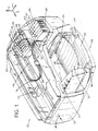
- FIG. 1 illustrates an embodiment of an inkjet printing mechanism, here shown as an "off-axis" inkjet printer 20, constructed in accordance with the present invention, which may be used for printing for business reports, correspondence, desktop publishing, and the like, in an industrial, office, home or other environment.
- inkjet printing mechanisms are commercially available.
- some of the printing mechanisms that may embody the present invention include plotters, portable printing units, copiers, cameras, video printers, and facsimile machines, to name a few, as well as various combination devices, such as a combination facsimile/printer.
- the concepts of the present invention are illustrated in the environment of an inkjet printer 20.
- the typical inkjet printer 20 includes a frame or chassis 22 surrounded by a housing, casing or enclosure 24, typically of a plastic material. Sheets of print media are fed through a printzone 25 by a media handling system 26.
- the print media may be any type of suitable sheet material, such as paper, card-stock, transparencies, photographic paper, fabric, mylar, and the like, but for convenience, the illustrated embodiment is described using paper as the print medium.
- the media handling system 26 has a feed tray 28 for storing sheets of paper before printing.
- a series of conventional paper drive rollers driven by a stepper motor and drive gear assembly may be used to move the print media from the input supply tray 28, through the printzone 25, and after printing, onto a pair of extended output drying wing members 30, shown in a retracted or rest position in FIG. 1.
- the wings 30 momentarily hold a newly printed sheet above any previously printed sheets still drying in an output tray portion 32, then the wings 30 retract to the sides to drop the newly printed sheet into the output tray 32.
- the media handling system 26 may include a series of adjustment mechanisms for accommodating different sizes of print media, including letter, legal, A-4, envelopes, etc., such as a sliding length adjustment lever 34, a sliding width adjustment lever 36, and an envelope feed port 38.
- the printer 20 also has a printer controller, illustrated schematically as a microprocessor 40, that receives instructions from a host device, typically a computer, such as a personal computer (not shown).
- the printer controller 40 may also operate in response to user inputs provided through a key pad 42 located on the exterior of the casing 24.
- a monitor coupled to the computer host may be used to display visual information to an operator, such as the printer status or a particular program being run on the host computer.
- personal computers, their input devices, such as a keyboard and/or a mouse device, and monitors are all well known to those skilled in the art.
- a carriage guide rod 44 is supported by the chassis 22 to slideably support an off-axis inkjet pen carriage system 45 for travel back and forth across the printzone 25 along a scanning axis 46.
- the carriage 45 is also propelled along guide rod 44 into a servicing region, as indicated generally by arrow 48, located within the interior of the housing 24.
- a conventional carriage drive gear and DC (direct current) motor assembly may be coupled to drive an endless belt (not shown), which may be secured in a conventional manner to the carriage 45, with the DC motor operating in response to control signals received from the controller 40 to incrementally advance the carriage 45 along guide rod 44 in response to rotation of the DC motor.
- a conventional encoder strip may extend along the length of the printzone 25 and over the service station area 48, with a conventional optical encoder reader being mounted on the back surface of printhead carriage 45 to read positional information provided by the encoder strip.
- the manner of providing positional feedback information via an encoder strip reader may be accomplished in a variety of different ways known to those skilled in the art.
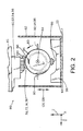
- the media sheet 34 receives ink from an inkjet cartridge, such as a black ink cartridge 50 and three monochrome color ink cartridges 52, 54 and 56, shown schematically in FIG. 2.
- the cartridges 50-56 are also often called "pens" by those in the art.
- the black ink pen 50 is illustrated herein as containing a pigment-based ink. While the illustrated color pens 52-56 may contain pigment-based inks, for the purposes of illustration, color pens 52-56 are described as each containing a dye-based ink of the colors cyan, magenta and yellow, respectively. It is apparent that other types of inks may also be used in pens 50-56, such as paraffin-based inks, as well as hybrid or composite inks having both dye and pigment characteristics.
- the illustrated pens 50-56 each include small reservoirs for storing a supply of ink in what is known as an "off-axis" ink delivery system, which is in contrast to a replaceable cartridge system where each pen has a reservoir that carries the entire ink supply as the printhead reciprocates over the printzone 25 along the scan axis 46.
- the replaceable cartridge system may be considered as an "on-axis” system, whereas systems which store the main ink supply at a stationary location remote from the printzone scanning axis are called “off-axis" systems.
- ink of each color for each printhead is delivered via a conduit or tubing system 58 from a group of main stationary reservoirs 60, 62, 64 and 66 to the on-board reservoirs of pens 50, 52, 54 and 56, respectively.
- the stationary or main reservoirs 60-66 are replaceable ink supplies stored in a receptacle 68 supported by the printer chassis 22.
- Each of pens 50, 52, 54 and 56 have printheads 70, 72, 74 and 76, respectively, which selectively eject ink to from an image on a sheet of media in the printzone 25.
- the printheads 70, 72, 74 and 76 each have an orifice plate with a plurality of nozzles formed therethrough in a manner well known to those skilled in the art.
- the nozzles of each printhead 70-76 are typically formed in at least one, but typically two linear arrays along the orifice plate.
- the term "linear” as used herein may be interpreted as “nearly linear” or substantially linear, and may include nozzle arrangements slightly offset from one another, for example, in a zigzag arrangement.
- Each linear array is typically aligned in a longitudinal direction perpendicular to the scanning axis 46, with the length of each array determining the maximum image swath for a single pass of the printhead.
- FIG. 2 illustrates one form of a dual-blade wiping service station 80 constructed in accordance with the present invention.
- the service station 80 includes a frame 82 which is supported by the printer chassis 22 in the servicing region 48 within the printer casing 24.
- the service station 80 includes a moveable platform supported by the service station frame 82.
- the servicing platform is shown as a rotary member supported by bearings or bushings (not shown) at the service station frame 82 for rotation, as illustrated by arrow 83, about an axis 84, which in the illustrated embodiment is parallel with printhead scanning axis 46.
- the illustrated rotary member comprises a tumbler body 85 which may have a drive gear 86 that is driven by a conventional service station motor and drive gear assembly (not shown).
- the tumbler 85 carries a series of servicing components, such as a capping assembly 88, into position for servicing the printheads 70-76.
- the capping assembly 88 preferably includes four discrete caps for sealing each of the printheads 70-76, although only a single capping unit is visible in the view of FIG. 2.
- the tumbler 85 may also be mounted to the service station frame 82 for movement in a vertical direction, as indicated by the double-headed arrow in FIG. 2, to facilitate capping.
- the capping assembly 88 may be mounted to the tumbler 85 to move upwardly away from tumbler 85 when moved into contact with the pens 50-56 or the carriage 45, for instance, using the capping strategy first sold by the present assignee, Hewlett-Packard Company of Palo Alto, California, in the models 850C and 855C DeskJet® inkjet printers.
- each of the wipers, 90-96 is constructed of a flexible, resilient, non-abrasive, elastomeric material, such as nitrile rubber, or more preferably, ethylene polypropylene diene monomer (EPDM), or other comparable materials known in the art.
- EPDM ethylene polypropylene diene monomer
- a suitable durometer that is, the relative hardness of the elastomer, may be selected from the range of 35-80 on the Shore A scale, or more preferably within the range of 60-80, or even more preferably at a durometer of 70 +/-5, which is a standard manufacturing tolerance.
- the black wiper 90 By placing the black wiper 90 along a different radial location on tumbler 85 than the radial on which the color wipers 92-96 are located, here, with the black and color wipers being shown 180° apart for the purposes of illustration, advantageously allows different wiping schemes to be employed for cleaning the black printhead 70 and for cleaning the color printheads 72-76.
- the color pens 52-56 carrying dye-based inks may be wiped using a faster wiping speed than required for wiping the black pen 50 which dispenses a black pigment-based ink.
- service station 80 which places the black wiper 90 and the color wipers 92-96 at different locations around the periphery of the tumbler 85, thus allowing wiping to be optimized for both the black printhead 70 and for the color printheads 72-76.
- the service station 80 includes a solvent dispensing system 98, mounted along the lower portion of the service station frame 82 in location where the wipers 90-96 can be coated with the solvent prior to wiping the printheads 70-76.
- the solvent dispensing system 98 also has a wiper cleaner portion to remove ink residue and any remaining solvent from the wipers after cleaning the printheads in a wiping cycle.
- the inkjet ink solvent used in system 98 may be a hygroscopic material, such as polyethylene glycol (“PEG”), lipponic-ethylene glycol (“LEG”), diethylene glycol (“DEG”), glycerin or other materials known to those skilled in the art as having similar properties.
- hygroscopic materials are liquid or gelatinous compounds that function as humectants, absorbing moisture from the air so they will not readily dry out during extended periods of time.
- the preferred ink solvent used in system 98 is PEG.
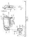
- FIG. 3 illustrates several details of the manner in which the pens 50-56 are installed within the carriage 45.
- the black pen 50 is shown, and the concepts illustrated herein are typical to pens 52, 54, and 56.
- the pen 50 includes an electrical interconnect 100 located along a rearward facing portion of the cartridge.
- the electrical interconnect 100 comprises a flexible strip which has a series of conductive contact pads located to be in electrical contact with a series of matching contact pads on a flex strip 102 mounted along an interior portion of the carriage 45.
- the carriage flex 102 is mounted above a pusher member 104, which is biased by a spring 105 to push the carriage flex strip 102 into contact with the pen flex 100, as illustrated by arrow 106 in FIG. 3.
- the pen flex 100 carries the electrical signals received from the carriage flex 102 to the firing resistors which heat the ink to eject droplets from nozzles 108 of printhead 70.
- the nozzles 108 are arranged as two substantially linear arrays which are perpendicular to the scan axis 46 when pen 50 is installed in carriage 45.
- the pen 50 has a straight, hollow inlet needle 110, located along a forward portion of the pen 50.
- the needle 110 is guarded by a shroud 112 to prevent an operator's fingers from inadvertently coming in contact with the needle.
- the carriage 45 also supports an inlet valve 114, which has an elastomeric septum 115 defining a preformed slit 116 therethrough.
- the valve 114 also has a flanged inlet port 118, to which a black ink tube 58' is coupled to receive black ink from the main reservoir 60.
- the black ink tube 58' is part of the tube assembly 58 in FIG. 1 that delivers ink from each of the main reservoirs 60-66 to the respective pens 50-56.
- the act of wiping the printhead 70 with wiper 90 also deposits ink on this nose portion 122 in two different ways.
- the first type of deposit known as “flicked ink,” occurs when wiping the printhead 70 by moving the wiper toward the rear of the printer 20, that is, to the right or negative Y direction in FIG. 3.
- the end tip of flexed wiper 90 clears the edge of the printhead 70, the elastomeric nature of the wiper tries to return to an upright rest position, but instead over-compensates, first by flexing to the far right, then unfortunately by swinging back to the left, eventually dampening out to an upright rest position.
- wiper scrape occurs when wiping the printhead 70 in the opposite direction toward the front of printer 20, that is, to the left or positive Y direction in FIG. 3.
- wiper 90 actually contacts the nose 122 because there is a mandatory interference fit between the wiper and the printhead face, which is required to flex the wiper into wiping contact with the printhead.
- the wiper scrapes any ink residue on the front surface of the blade directly onto the nose 122.
- the inlet needle 110 on the pen 50 is rigidly mounted within the shroud to pierce the septum 115 along slit 116 during pen installation.
- the shroud 112 is sized to surround the valve 114. While the valve 114 is preferably constructed to tilt slightly with respect to the carriage 45, it is apparent from this construction that insertion of needle 110 into septum 115, as well as removal therefrom, must use a substantially linear motion as indicated by arrow 123 in FIG. 3.
- pen installation/removal for the inlet valve 114 at the front of the cartridge must be in a substantially vertical direction 123, then installation/removal at the rear of the cartridge where the electrical interconnect is located must also be vertical, as illustrated by arrow 124 in FIG. 3.
- pens 50-56 may be replaced because, while the desire is to have a permanent system for printheads 70-76, they may be more of a semi-permanent nature, or a user may wish to switch to different types of ink, requiring the pens 50-56 to be removed from carriage 45.
- these off-axis pens 50-56 reside within printer 20 for an extended period of time, which exposes the cartridge nose 122 for a long time to accumulate a significant amount of ink residue 120.
- FIGS. 4-6 a service station based, active electrical interconnect cleaning system 125 constructed in accordance with the present invention is illustrated.
- the service station 80 includes an L-shaped interconnect wiper member 130 extending from the tumbler 85 to terminate in a wiping arm 132.
- FIG. 4 we see the tumbler 85 has been moved toward the printhead, as indicated by arrow 126.
- FIG. 5 shows the next step of this active interconnect cleaning process, where the tumbler 85 has been rotated, as indicated by arrow 83, so the wiper 130 contacts the pen interconnect flex 100 to the point where the arm portion 132 is slightly flexed, to ensure an active wiping contact and engagement with the flex 100.
- FIG. 6 shows the next portion of this active interconnect cleaning operation, where the tumbler 85 is retracted away from the printhead 70, here being lowered as indicated by arrow 128, to allow arm 132 to scrape the ink residue 120 from the vertical nose portion 122 of the flex 100. It is apparent that in transitioning from the position of FIG. 5 to FIG. 6, there may also be some rotation of the tumbler 85, in the direction indicated by arrow 83, but in the preferred embodiment the motion is generally linear, moving the tumbler 85 and the wiper arm 130 downwardly and away from carriage 45 to clean this vertical portion of the interconnect 100.
- FIGS. 4-6 The manner of initiating the active wiping sequence of FIGS. 4-6 may be easily implemented by incorporating features in to printer 20 which are currently available on a variety of commercial inkjet printers, such as the DeskJet® inkjet printers sold in the 500, 600, and 800 models series, all of which currently use replaceable cartridges. Nonetheless, these commercially available inkjet printers are provided with an interlock switch on the pen access door, which a user must open to change cartridges, and such a conventional system is included on printer 20.
- inkjet printers such as the DeskJet® inkjet printers sold in the 500, 600, and 800 models series, all of which currently use replaceable cartridges. Nonetheless, these commercially available inkjet printers are provided with an interlock switch on the pen access door, which a user must open to change cartridges, and such a conventional system is included on printer 20.
- the design philosophy has been to move the carriage away from the servicing region 48, so upon installation of a fresh pen a user does not have to overcome the forces of the printhead capping assembly.
- This system assures that the pens are installed tightly against their alignment datums in the carriage without interference from the printhead caps.
- These pen alignment datums such as ears 134 in FIG. 3, mate against matching carriage alignment datums to align the pen with the carriage in the X, Y and Z directions, as well as with respect to the ⁇ X , ⁇ Y and ⁇ Z rotational degrees of freedom about these axes, to ensure accurate dot placement on the media.
- This pen access scheme used to ensure proper alignment of the pens may advantageously be used in the active wiping system 125 of FIGS. 4-6.
- the printer controller 40 Upon activation of the pen access door interlock switch, which may be an optical, electrical, magnetic or some other form of switching mechanism, the printer controller 40 initiates the operation of FIGS. 4-6 to clean the interconnect nose portion 100 of pens 50-56, before moving the carriage 45 to the pen access position.
- the pen servicing routine and the operation of controller 40, to implement the active interconnect cleaning system of FIGS. 4-6.
- controller 40 then moves carriage 45 to the pen access position for pen removal and installation.
- each of these commercially available printers mentioned above as having such an interlock system also have various systems to defeat pen removal in an unpowered state, so if the power cord to the printer is disconnected, the pens cannot be removed.
- the design philosophy behind this process is to ensure that the pen datums are seated tightly against their associated carriage alignment datums, without any potential interference from the service station, and particularly from the capping mechanism of the service station.
- a final reason for such a pen access interlock system is also to prevent any inadvertent damage to the service station components during installation of new pens.
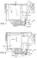
- FIGS. 7-10 illustrate one embodiment of a carriage based, passive electrical interconnect cleaning system 135, constructed in accordance with the present invention to remove ink residue 120 from the nose portion 122 of cartridges 50-56.
- the carriage 45 is modified to include passive wiper arms 140, 142, 144 and 146 for cleaning ink residue 120 from cartridges 50, 52, 54 and 56, respectively.
- the wiper members 140, 142, 144 and 146 prevent the ink residue 120 from being smeared across the associated carriage interconnects 102, 102', 102" and 102"', respectively.
- each wiper member 140-146 includes a spring arm 148 that supports a wiper head 150, preferably attached to a spatula-shaped bottom portion 152 of the spring arm 148.
- the spring arm 148 is preferably constructed of a spring stainless steel, such as of a AISI 301 stainless steel alloy, half-hard rolled, such as from stock which is about 0.20mm (0.008 inches) thick.
- the wiper head 150 is preferably onsert molded to the spring arm 148, using techniques known to those skilled in the art.
- the wiper head 150 is preferably constructed of an elastomeric material as described above with respect to the printhead wipers 90-96, and most preferably of an EPDM elastomer having a durometer of 40-70, or more preferably of 50 +/- 5 on the Shore A scale.
- the wiper head 150 may be constructed of an absorbent, fibrous material, such as a of a blotter paper or a hard pressed cardboard which is bonded to the spring arms 140-146.
- One suitable absorbent wiper head 150 may be constructed from the same paperboard stock used to make beer coasters which are distributed in taverns to be placed under a customer's beverage glass.
- the spring arm 148 is constructed and installed in the carriage 45 to provide a biasing force to urge the wiper head 150 in a direction toward the pen interconnects 102-102''', as illustrated in FIG. 9 by arrow 154.
- This spring biasing provided by arm 148 toward the cartridges 50-56 advantageously pushes the wiper head 150 into contact with the lower nose portion 122 of the pen interconnects 100, as shown in FIG. 7.
- the passive electrical interconnect cleaner 135 of FIGS. 7-10 removes the accumulated ink residue 120 from the nose portion 122 of pens 50-56, as illustrated in detail with respect to FIG. 7 and 8.
- FIG. 8 shows in dashed lines the initial printing position of cartridge 50, representative of all of the cartridges 50-56, with the cartridge 50 being removed as indicated by arrow 156 vertically, for the reasons described above with respect to FIG. 3.
- the wiping member 140 is shown with arm 148 pushing the wiper head 150 into contact with the pen flex 100, removing the ink residue 120 thereon from the vertical surface of flex 100, as shown in FIG. 8.
- the cartridge 50 may be removed from carriage 45 without smearing or depositing any of this ink residue 120 along the carriage interconnect 102.
- no ink residue gets deposited upon the carriage interconnect 102, so upon insertion of a fresh cartridge, there is no shorting out of the contact pads of interconnects 100, 102 by ink residue.
- the residue 120 does not become deposited upon the carriage interconnect 102.
- the passive interconnect cleaner system 135 of FIG. 7-10 avoids shorting out of the contact pads of interconnects 100, 102.
- an active system 125 and a passive system 135 for cleaning ink residue 120 from an exterior portion of inkjet cartridges 50-56, and here, the nose portion 122 of the electrical interconnect 100, to prevent ink residue 120 from smearing onto critical components of the printer/carriage interface, here, the electrical interconnects 100 and 102.
- the passive cleaning system 135 of FIGS. 7-10 may be preferred for some implementations over the active cleaning system 125 of FIGS. 4-6, simply because the service station servicing algorithms for maintaining the health of printheads 70-76 need not be further complicated by the additional step of cleaning the interconnect with wiper member 130.
- the passive system 135 imposes no additional burden on the controller 40, and imposes no additional delay of any sort before allowing a user to remove the pens 50-56 from carriage 45.
- both the active cleaner system 125 and the passive cleaner system 135 advantageously clean ink residue 120 from cartridges 50-56 without requiring any user intervention beyond the normal operation of pen removal.
- these cleaning systems 125 and 135 are very reliable because there is no chance for a user to forget to perform these functions while changing pens.
- the active cleaning system 125 advantageously uses the functional abilities inherent in service station 80 for servicing printheads 70-76, and just adds four extra cleaner members 130 to the tumbler 85, one for each of the pens 50-56.
- to activate the sequence of FIGS. 4-6 already installed features within commercial inkjet printers, and within printer 20, are used. That is, the notification to the controller 40 that a user wishes to replace a cartridge is used to initialize the cleaning sequence.
- the passive system advantageously uses the spring arm 148 to push the flex circuit 100 toward the main body of the pens 50-56, which further ensures that the nose portion 122 of the flex strip 100 will not inadvertently contact any other printer components while traversing the printzone 25.
- the spatula based bottom portion 152 of the spring arm 148 advantageously shields the majority of the nose portion 122 of the pen flex 100 from having ink residue initially deposited thereon.
- the narrow "handle" portion of arms 140-146 above the spatula end 148 advantageously lowers the spring force exerted by the arms to prevent inadvertent damage to the pen flex strips 100, and to minimize the effort required to seat the pens on their alignment datums in the carriage.
- both the active and passive electrical interconnect cleaner systems 125 and 135 advantageously provide the consumer with a more reliable inkjet printer 20, with a prolonged life, even through interchanges of the semi-permanent printhead cartridges 50-56. Furthermore, it is apparent that while the systems 125, 135 have been illustrated with respect to an off-axis inkjet printer 20, the systems may be readily adaptive for use on a replaceable cartridge inkjet printer to remove ink residue from a critical exterior portion of the replaceable cartridges.
Landscapes
- Ink Jet (AREA)
Claims (12)
- Système de nettoyage (125 ; 135) destiné à enlever un résidu d'encre accumulé (120) d'une portion extérieure non imprimante d'une cartouche à jet d'encre (50, 52, 54, 56) dans un mécanisme d'impression à jet d'encre (20), la portion extérieure non imprimante se trouvant dans un plan qui est de façon générale transversal à un plan défini par une surface d'impression de la cartouche d'impression (50, 52, 54, 56), le système de nettoyage comprenant :une raclette (130 ; 140, 142, 144, 146) ; etun élément de support (85 ; 45) qui supporte la raclette (130 ; 140, 142, 144, 146) dans une position appropriée pour enlever le résidu d'encre accumulé (120) de la portion extérieure non imprimante de la cartouche (50, 52, 54, 56) par un mouvement relatif de la raclette (130 ; 140, 142, 144, 146) et de la cartouche (50, 52, 54, 56).
- Système de nettoyage selon la revendication 1, dans lequel :les deux plans précités sont sensiblement perpendiculaires entre eux.
- Système de nettoyage selon la revendication 1 ou la revendication 2, dans lequel :l'élément de support comprend une plate-forme mobile (85) qui supporte la raclette (130); etledit mouvement relatif est réalisé par la plate-forme (85) qui met la raclette (130) en contact de raclage avec la portion extérieure non imprimante de la cartouche (50, 52, 54, 56) pour racler le résidu d'encre (120) de cette portion.
- Système de nettoyage selon la revendication 1 ou la revendication 2, dans lequel :l'élément de support comprend un chariot (45) qui porte la cartouche (50, 52, 54, 56) ; etledit mouvement relatif se produit lorsqu'on retire la cartouche (50, 52, 54, 56) du chariot (45).
- Système de nettoyage selon la revendication 4, dans lequel :la raclette (140, 142, 144, 146) comprend un bras (148) sollicité par ressort qui a une extrémité proximale supportée par le chariot (45) et une extrémité distale (152) ;la raclette comprend une tête de raclette (150) supportée par l'extrémité distale du bras (148) sollicité par ressort ; etle bras (148) sollicité par ressort presse la tête de raclette (150) en contact de raclage avec ladite portion extérieure non imprimante de la cartouche (50, 52, 54, 56) lorsqu'on retire la cartouche (50, 52, 54, 56) du chariot (45).
- Système de nettoyage selon une quelconque des revendications précédentes, dans lequel la portion extérieure non imprimante de la cartouche (50, 52, 54, 56) comprend une portion d'une interconnexion électrique (100).
- Système de nettoyage selon la revendication 5, dans lequel :la portion extérieure non imprimante de la cartouche (50, 52, 54, 56) comprend une portion d'une interconnexion électrique (100) ; etl'extrémité distale (152) du bras (148) sollicité par ressort a une forme qui protège une autre portion de l'interconnexion électrique (100) de l'accumulation de résidu d'encre.
- Mécanisme d'impression à jet d'encre (20), comprenant :une cartouche à jet d'encre (50, 52, 54, 56) ayant une tête d'impression (70, 72, 74, 76) qui éjecte de l'encre hors de cette cartouche pour imprimer, et une portion extérieure non imprimante qui accumule un résidu d'encre sur elle ; etun système de nettoyage selon une quelconque des revendications précédentes.
- Procédé de nettoyage d'un résidu d'encre accumulé (120) d'une portion extérieure non imprimante d'une cartouche à jet d'encre (50, 52, 54, 56) dans un mécanisme d'impression à jet d'encre (20), la portion extérieure non imprimante se trouvant dans un plan qui est de façon générale transversal à un plan défini par une surface imprimante de la cartouche à jet d'encre (50, 52, 54, 56), le procédé comprenant les étapes consistant à :prévoir une raclette (130 ; 140, 142, 144, 146) supportée par un élément de support (85 ; 45) ; eten réponse à une action effectuée par l'utilisateur pour retirer la cartouche (50, 52, 54, 56) du mécanisme d'impression (20), enlever le résidu d'encre accumulé (120) de la portion extérieure non imprimante de la cartouche à jet d'encre (50, 52, 54, 56) par un mouvement relatif de la raclette (130 ; 140, 142, 144, 146) et de la cartouche (50, 52, 54, 56).
- Procédé selon la revendication 9, dans lequel les deux plans précités sont sensiblement perpendiculaires entre eux.
- Procédé selon la revendication 9 ou la revendication 10, dans lequel :l'étape consistant à prévoir consiste à prévoir l'élément de support sous la forme d'une plate-forme mobile (85) ; etl'étape d'enlèvement consiste à mettre la raclette (130) avec la plate-forme (85) en contact de raclage avec la portion extérieure non imprimante de la cartouche à jet d'encre (50, 52, 54, 56) pour racler le résidu d'encre (120) de cette portion.
- Procédé selon la revendication 9 ou la revendication 10, dans lequel :l'étape consistant à prévoir consiste à prévoir la raclette (140, 142, 144, 146) sous la forme d'une tête de raclette (150) supportée par un bras (48) sollicité par ressort, qui est supporté par un chariot (45) qui porte la cartouche (50, 52, 54, 56) ; etl'étape d'enlèvement consiste à retirer la cartouche (50, 52, 54, 56) du chariot (45) tout en pressant la tête de raclette (150) avec le bras (148) sollicité par ressort, en contact de raclage avec la portion extérieure non imprimante de la cartouche à jet d'encre (50, 52, 54, 56) pour racler le résidu d'encre (120) de cette portion.
Applications Claiming Priority (2)
| Application Number | Priority Date | Filing Date | Title |
|---|---|---|---|
| US96105097A | 1997-10-30 | 1997-10-30 | |
| US961050 | 1997-10-30 |
Publications (2)
| Publication Number | Publication Date |
|---|---|
| EP0914953A1 EP0914953A1 (fr) | 1999-05-12 |
| EP0914953B1 true EP0914953B1 (fr) | 2002-05-08 |
Family
ID=25503998
Family Applications (1)
| Application Number | Title | Priority Date | Filing Date |
|---|---|---|---|
| EP98308581A Expired - Lifetime EP0914953B1 (fr) | 1997-10-30 | 1998-10-20 | Système de nettoyage d'interconnexion électrique pour cartouches à jet d'encre |
Country Status (3)
| Country | Link |
|---|---|
| US (1) | US6575553B1 (fr) |
| EP (1) | EP0914953B1 (fr) |
| DE (1) | DE69805266T2 (fr) |
Families Citing this family (17)
| Publication number | Priority date | Publication date | Assignee | Title |
|---|---|---|---|---|
| US7456393B2 (en) * | 2003-04-10 | 2008-11-25 | Ge Homeland Protection, Inc. | Device for testing surfaces of articles for traces of explosives and/or drugs |
| US20050045205A1 (en) * | 2003-08-29 | 2005-03-03 | Stach Steven R. | Apparatus and method for cleaning printed circuit boards |
| US7066572B2 (en) * | 2003-11-03 | 2006-06-27 | Hewlett-Packard Development Company, L.P. | Printing system |
| JP4812078B2 (ja) * | 2004-12-28 | 2011-11-09 | キヤノン株式会社 | インクジェット記録装置 |
| JP4849978B2 (ja) * | 2006-07-07 | 2012-01-11 | 株式会社リコー | インクジェットプリンタのヘッドクリーニング装置及びインクジェットプリンタ |
| US20100059084A1 (en) * | 2008-09-10 | 2010-03-11 | Austin American Technology Corporation | Cleaning and testing ionic cleanliness of electronic assemblies |
| JP5384153B2 (ja) * | 2009-03-17 | 2014-01-08 | ローランドディー.ジー.株式会社 | インクジェット式記録装置 |
| JP5317780B2 (ja) * | 2009-03-17 | 2013-10-16 | ローランドディー.ジー.株式会社 | インクジェット式記録装置 |
| US8348414B2 (en) * | 2009-07-30 | 2013-01-08 | Roland Dg Corporation | Ink jet recording apparatus equipped with cutting head and ultraviolet light irradiation device |
| US8562104B2 (en) * | 2010-05-17 | 2013-10-22 | Zamtec Ltd | Maintenance system having cleanable wiper for printhead |
| ITVI20120278A1 (it) | 2012-10-22 | 2014-04-23 | New System Srl | Gruppo di stampa del tipo perfezionato e dispositivo di stampa a getto d'inchiostro comprendente il suddetto gruppo di stampa |
| CN105531120B (zh) | 2013-09-17 | 2019-04-19 | 惠普发展公司,有限责任合伙企业 | 清洁垫 |
| WO2015088545A1 (fr) * | 2013-12-13 | 2015-06-18 | Hewlett-Packard Development Company, L.P. | Protection remplaçable pour tête d'impression |
| WO2017074415A1 (fr) | 2015-10-30 | 2017-05-04 | Hewlett-Packard Development Company, L.P. | Ensemble charnière |
| JP6578915B2 (ja) * | 2015-12-02 | 2019-09-25 | ブラザー工業株式会社 | メンテナンス部材 |
| JP6686546B2 (ja) * | 2016-03-07 | 2020-04-22 | セイコーエプソン株式会社 | 液体噴射装置 |
| TWI711487B (zh) * | 2017-04-21 | 2020-12-01 | 三緯國際立體列印科技股份有限公司 | 噴頭清潔模組 |
Family Cites Families (13)
| Publication number | Priority date | Publication date | Assignee | Title |
|---|---|---|---|---|
| JP2944767B2 (ja) | 1991-02-06 | 1999-09-06 | キヤノン株式会社 | インクジェット記録装置 |
| JP2872431B2 (ja) | 1991-04-22 | 1999-03-17 | キヤノン株式会社 | インクジェット記録装置 |
| US5396271A (en) * | 1992-11-12 | 1995-03-07 | Xerox Corporation | Wiper blade cleaning system for non-coplanar nozzle faces of ink jet printheads |
| US5598194A (en) | 1993-04-30 | 1997-01-28 | Hewlett-Packard Company | Wiping structure for cleaning electrical contacts for a printer and ink cartridge |
| US5559539A (en) | 1993-10-12 | 1996-09-24 | Dataproducts Corporation | Ink jet recording apparatus having self aligning print head cleaning system and method of operating the print head cleaning system |
| US5706038A (en) * | 1994-10-28 | 1998-01-06 | Hewlett-Packard Company | Wet wiping system for inkjet printheads |
| DE69631741T2 (de) * | 1995-07-31 | 2005-03-17 | Hewlett-Packard Co. (N.D.Ges.D.Staates Delaware), Palo Alto | Instandsetzungsstelle mit translatorischer Bewegung für Farbstrahldruckköpfe |
| JPH09150521A (ja) * | 1995-11-29 | 1997-06-10 | Funai Electric Co Ltd | 印字ヘッド清掃用ワイパー |
| US5736997A (en) | 1996-04-29 | 1998-04-07 | Lexmark International, Inc. | Thermal ink jet printhead driver overcurrent protection scheme |
| US5936647A (en) * | 1996-10-31 | 1999-08-10 | Hewlett-Packard Company | Flexible frame onsert capping of inkjet printheads |
| US5907335A (en) | 1996-11-13 | 1999-05-25 | Hewlett-Packard Company | Wet wiping printhead cleaning system using a non-contact technique for applying a printhead treatment fluid |
| US6132037A (en) | 1997-09-03 | 2000-10-17 | Bartolome; Jordi | Storage container for inkjet cartridges having cleaning means and a method for storing inkjet cartridges |
| US6155667A (en) * | 1999-01-08 | 2000-12-05 | Hewlett-Packard Company | Replaceable snout wiper for inkjet cartridges |
-
1998
- 1998-10-20 EP EP98308581A patent/EP0914953B1/fr not_active Expired - Lifetime
- 1998-10-20 DE DE69805266T patent/DE69805266T2/de not_active Expired - Fee Related
-
2000
- 2000-04-28 US US09/560,430 patent/US6575553B1/en not_active Expired - Fee Related
Also Published As
| Publication number | Publication date |
|---|---|
| US6575553B1 (en) | 2003-06-10 |
| EP0914953A1 (fr) | 1999-05-12 |
| DE69805266T2 (de) | 2002-08-29 |
| DE69805266D1 (de) | 2002-06-13 |
Similar Documents
| Publication | Publication Date | Title |
|---|---|---|
| EP0913263B1 (fr) | Dispositif escamotable pour nettoyer les balais de têtes d'impression à jet d'encre | |
| EP1018429B1 (fr) | Système de capuchon remplaçable pour têtes d'impression à jet d'encre | |
| US6601943B2 (en) | Indexing scraper cleaning system for inkjet printheads | |
| US6155667A (en) | Replaceable snout wiper for inkjet cartridges | |
| US6481822B2 (en) | Independent servicing of multiple inkjet printheads | |
| EP1095775B1 (fr) | Raclette double pour balai d'essuyage pour imprimantes utilisant des encres incompatibles | |
| US20020191043A1 (en) | Sliced sponge scraper system for inkjet wipers | |
| US6575553B1 (en) | Inkjet residue cleaning system for inkjet cartridges | |
| EP1018431B1 (fr) | Dispositif d'application de solvant d'encre remplaçable pour imprimantes à jet d'encre | |
| US6050671A (en) | Stalagmite dissolving spittoon system for inkjet printheads | |
| US6644778B2 (en) | Stalagmite dissolving spittoon system for inkjet printheads | |
| US6561619B1 (en) | Flipping wiper scraper system for inkjet printheads | |
| EP1078765B1 (fr) | Bout de balai entaillé pour le nettoyage de têtes d'impression à jet d'encre | |
| US6409303B1 (en) | Two-stage scraper system for inkjet wipers | |
| EP1018430A1 (fr) | Système d'application de solvant d'encre pour imprimante à jet d'encre | |
| US6318837B1 (en) | Bristled scraper cleaning system for inkjet printheads | |
| EP0913262A1 (fr) | Système de nettoyage avec balais d'essuyage larges et étroits pour têtes d'impression par jet d'encre | |
| US6402291B1 (en) | Composite wiper for inkjet printheads | |
| EP1033253B1 (fr) | Système de protection contre l'encre, pour imprimante à jet d'encre | |
| EP1029683A1 (fr) | Nettoyage indépendant pour plusieurs têtes d'impression à jet d'encre |
Legal Events
| Date | Code | Title | Description |
|---|---|---|---|
| PUAI | Public reference made under article 153(3) epc to a published international application that has entered the european phase |
Free format text: ORIGINAL CODE: 0009012 |
|
| AK | Designated contracting states |
Kind code of ref document: A1 Designated state(s): DE GB |
|
| AX | Request for extension of the european patent |
Free format text: AL;LT;LV;MK;RO;SI |
|
| 17P | Request for examination filed |
Effective date: 19990705 |
|
| AKX | Designation fees paid |
Free format text: DE GB |
|
| 17Q | First examination report despatched |
Effective date: 20000801 |
|
| RAP1 | Party data changed (applicant data changed or rights of an application transferred) |
Owner name: HEWLETT-PACKARD COMPANY, A DELAWARE CORPORATION |
|
| GRAG | Despatch of communication of intention to grant |
Free format text: ORIGINAL CODE: EPIDOS AGRA |
|
| GRAG | Despatch of communication of intention to grant |
Free format text: ORIGINAL CODE: EPIDOS AGRA |
|
| GRAH | Despatch of communication of intention to grant a patent |
Free format text: ORIGINAL CODE: EPIDOS IGRA |
|
| GRAH | Despatch of communication of intention to grant a patent |
Free format text: ORIGINAL CODE: EPIDOS IGRA |
|
| REG | Reference to a national code |
Ref country code: GB Ref legal event code: IF02 |
|
| GRAA | (expected) grant |
Free format text: ORIGINAL CODE: 0009210 |
|
| AK | Designated contracting states |
Kind code of ref document: B1 Designated state(s): DE GB |
|
| REF | Corresponds to: |
Ref document number: 69805266 Country of ref document: DE Date of ref document: 20020613 |
|
| PLBE | No opposition filed within time limit |
Free format text: ORIGINAL CODE: 0009261 |
|
| STAA | Information on the status of an ep patent application or granted ep patent |
Free format text: STATUS: NO OPPOSITION FILED WITHIN TIME LIMIT |
|
| 26N | No opposition filed |
Effective date: 20030211 |
|
| PGFP | Annual fee paid to national office [announced via postgrant information from national office to epo] |
Ref country code: DE Payment date: 20071130 Year of fee payment: 10 |
|
| PG25 | Lapsed in a contracting state [announced via postgrant information from national office to epo] |
Ref country code: DE Free format text: LAPSE BECAUSE OF NON-PAYMENT OF DUE FEES Effective date: 20090501 |
|
| REG | Reference to a national code |
Ref country code: GB Ref legal event code: 732E Free format text: REGISTERED BETWEEN 20120329 AND 20120404 |
|
| PGFP | Annual fee paid to national office [announced via postgrant information from national office to epo] |
Ref country code: GB Payment date: 20130923 Year of fee payment: 16 |
|
| GBPC | Gb: european patent ceased through non-payment of renewal fee |
Effective date: 20141020 |
|
| PG25 | Lapsed in a contracting state [announced via postgrant information from national office to epo] |
Ref country code: GB Free format text: LAPSE BECAUSE OF NON-PAYMENT OF DUE FEES Effective date: 20141020 |