EP0915047A1 - Maschine für die Handhabung von Rollen, insbesondere für Papierproduktionslinien - Google Patents
Maschine für die Handhabung von Rollen, insbesondere für Papierproduktionslinien Download PDFInfo
- Publication number
- EP0915047A1 EP0915047A1 EP98111964A EP98111964A EP0915047A1 EP 0915047 A1 EP0915047 A1 EP 0915047A1 EP 98111964 A EP98111964 A EP 98111964A EP 98111964 A EP98111964 A EP 98111964A EP 0915047 A1 EP0915047 A1 EP 0915047A1
- Authority
- EP
- European Patent Office
- Prior art keywords
- arms
- reel
- machine
- driving apparatus
- arm
- Prior art date
- Legal status (The legal status is an assumption and is not a legal conclusion. Google has not performed a legal analysis and makes no representation as to the accuracy of the status listed.)
- Granted
Links
- 239000000463 material Substances 0.000 title claims abstract description 13
- 238000004519 manufacturing process Methods 0.000 title claims abstract description 10
- 239000000123 paper Substances 0.000 description 15
- 238000006073 displacement reaction Methods 0.000 description 7
- 230000020347 spindle assembly Effects 0.000 description 5
- 230000000712 assembly Effects 0.000 description 4
- 238000000429 assembly Methods 0.000 description 4
- 230000000875 corresponding effect Effects 0.000 description 3
- 238000000926 separation method Methods 0.000 description 2
- 238000004804 winding Methods 0.000 description 2
- 230000008602 contraction Effects 0.000 description 1
- 230000002596 correlated effect Effects 0.000 description 1
- 230000007547 defect Effects 0.000 description 1
- 238000010586 diagram Methods 0.000 description 1
- 238000009434 installation Methods 0.000 description 1
- 230000007257 malfunction Effects 0.000 description 1
- 238000000034 method Methods 0.000 description 1
- 230000010355 oscillation Effects 0.000 description 1
- 239000011087 paperboard Substances 0.000 description 1
- 230000003245 working effect Effects 0.000 description 1
Images


Classifications
-
- B—PERFORMING OPERATIONS; TRANSPORTING
- B65—CONVEYING; PACKING; STORING; HANDLING THIN OR FILAMENTARY MATERIAL
- B65H—HANDLING THIN OR FILAMENTARY MATERIAL, e.g. SHEETS, WEBS, CABLES
- B65H19/00—Changing the web roll
- B65H19/10—Changing the web roll in unwinding mechanisms or in connection with unwinding operations
- B65H19/12—Lifting, transporting, or inserting the web roll; Removing empty core
- B65H19/126—Lifting, transporting, or inserting the web roll; Removing empty core with both-ends supporting arrangements
-
- B—PERFORMING OPERATIONS; TRANSPORTING
- B65—CONVEYING; PACKING; STORING; HANDLING THIN OR FILAMENTARY MATERIAL
- B65H—HANDLING THIN OR FILAMENTARY MATERIAL, e.g. SHEETS, WEBS, CABLES
- B65H19/00—Changing the web roll
- B65H19/22—Changing the web roll in winding mechanisms or in connection with winding operations
- B65H19/30—Lifting, transporting, or removing the web roll; Inserting core
-
- B—PERFORMING OPERATIONS; TRANSPORTING
- B65—CONVEYING; PACKING; STORING; HANDLING THIN OR FILAMENTARY MATERIAL
- B65H—HANDLING THIN OR FILAMENTARY MATERIAL, e.g. SHEETS, WEBS, CABLES
- B65H2301/00—Handling processes for sheets or webs
- B65H2301/40—Type of handling process
- B65H2301/41—Winding, unwinding
- B65H2301/417—Handling or changing web rolls
- B65H2301/4171—Handling web roll
- B65H2301/4172—Handling web roll by circumferential portion, e.g. rolling on circumference
-
- B—PERFORMING OPERATIONS; TRANSPORTING
- B65—CONVEYING; PACKING; STORING; HANDLING THIN OR FILAMENTARY MATERIAL
- B65H—HANDLING THIN OR FILAMENTARY MATERIAL, e.g. SHEETS, WEBS, CABLES
- B65H2301/00—Handling processes for sheets or webs
- B65H2301/40—Type of handling process
- B65H2301/41—Winding, unwinding
- B65H2301/417—Handling or changing web rolls
- B65H2301/4171—Handling web roll
- B65H2301/4173—Handling web roll by central portion, e.g. gripping central portion
-
- B—PERFORMING OPERATIONS; TRANSPORTING
- B65—CONVEYING; PACKING; STORING; HANDLING THIN OR FILAMENTARY MATERIAL
- B65H—HANDLING THIN OR FILAMENTARY MATERIAL, e.g. SHEETS, WEBS, CABLES
- B65H2405/00—Parts for holding the handled material
- B65H2405/40—Holders, supports for rolls
- B65H2405/42—Supports for rolls fully removable from the handling machine
- B65H2405/422—Trolley, cart, i.e. support movable on floor
Definitions
- the present invention relates to a machine for reel handling, in particular for paper material production lines, of the type comprising at least one pair of handling arms to be positioned at the opposite end faces of a reel and movable between a lowered loading or unloading position and a raised work position, as described in the preamble of Claim 1.
- paper or paperboard reels are required to be moved from lowered positions corresponding to the positions of the carriages usually sliding on rails on which said reels are disposed, to raised work positions, and vice versa from the last-mentioned positions to the former.
- reel-handling operations apparatuses of various kinds can be used, which are for example either of general use and of the moving type such as elevators, or in the form of specific and dedicated apparatuses such as handler arms oscillatably connected to a base structure.
- the handler arms generally consist of levers emerging from a base structure and spaced apart from each other by a distance proportional to the longitudinal sizes of the reels to be lifted or lowered.
- These handler arms have free ends provided with grasping means capable of engaging the hollow cores of the reels on opposite sides and therefore these arms are such movable that they get closed clamp-wise on the end faces of the reels or they open for release.
- the hollow cores of the reels to be gripped are required to be exactly in alignment with the grasping means supported by the handler arms, to enable said arms to close clamp-wise.
- the handler arms are provided with a rotatory motion about a horizontal axis and therefore the grasping means describes a trajectory in the form of an arc of a circle capable of intercepting the hollow core of a reel placed on a carriage only if this core is at a predetermined fixed height, corresponding to a reel of standard and constant diameter.
- the technical task of the present invention is to devise a reel handling machine capable of substantially obviating the above drawbacks.
- Another important aim of the invention is to devise a flexible and adjustable machine capable of enabling the most appropriate positioning of a reel to be achieved, when said reel has been raised and is being unwound, so that possible imprecisions of the same are compensated for, without however introducing uncertainty or imprecision elements in the reel positioning.
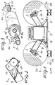
- the machine in accordance with the invent ion has been generally identified by reference numeral 1 . It comprises, as shown in Figs. 2 and 4, a base structure 2 alongside which there are rails 2a on which preferably power-driven carriages 2b run.
- the base structure 2 defines at least a pivot axis 4 which is substantially horizontal or parallel to the rest surface of the machine 1, along which a shaft 4a of great length or two shafts 4a coaxial with each other are disposed.
- Linked to the base structure 2 is at least one pair of handler arms 3 , merely referred to as arms 3 in the following. Two pairs of arms 3 are shown in the figures and each pair is independent of the other pair.
- Arms 3 of each pair are disposed in side by side relationship and spaced apart from each other and they are simultaneously movable with at least two movements: a rotatory movement around the shaft 4a coaxial with the horizontal pivot axis 4, and a translational movement along shaft 4a and the pivot axis 4.
- Said translational movement is provided to enable the arms 3 of each arm pair to move close to or away from each other, in order to conform the distance between said arms to the axial sizes of a reel 5 to be submitted to movement.
- Said reel 5 (Fig. 3) externally has a cylindrical surface and two end faces 5a which are substantially flat and parallel to each other, and internally has a cylindrical and hollow core 5b , coaxial with a central axis 6 . Intersection between the central axis 6 and the two end faces 5a defines two centres identified by 5c .
- each reel 5 is loaded or unloaded always in an extended position, that is with its central axis 6 substantially horizontal, onto and from a respective carriage 2b guided by rails 2a. Therefore in the loading or unloading positions the central axis 6, seen in plan view, always lies centrally over rails 2a and a respective carriage 2b, independently of the diameter of reel 5.
- the rotatory movement enables displacement of each arm 3 between lowered loading/unloading positions of a reel 5 and one or more raised work positions, to be used for the intended operations to which reel 5 is to be submitted.
- Movements of arms 3 are controlled by a driving apparatus 7 , described in the following.
- Arms 3 are integral with grasping means consisting of heads 8 projecting from arms 3 and adapted to be fitted into the core 5b when arms 3 are close to each other.
- heads 8 are provided with a spindle assembly 8a to be fitted in core 5b, a flange assembly 8b supporting the spindle assembly 8a, and a control unit 8c .
- the control unit 8c controls rotation of the two above mentioned assemblies and therefore of the whole reel 5, by means of a clutch device preventing accidental rotations of reel 5.
- the spindle and flange assemblies 8a and 8b are integral with each other and oscillatable along a short stroke towards arm 3, when the flange assembly 8b is submitted to the pressure of an edge of core 5b. This oscillation movement actuates a contrivance inside the spindle assembly 8a causing expansion of keys 8d placed on the spindle assembly itself, so as to lock core 5b from the inside.
- the spindle and flange assemblies 8a and 8b embody an expanding spindle, known per se.
- Arms 3 are defined by a plurality of mutually movable rigid portions, which portions are in particular mutually movable in order to be able to continuously vary the position of each arm 3 between a contracted setting, defining the minimum length of arm 3, and an extended setting defining the maximum length of arm 3.
- each arm 3 comprises a rigid first portion 9 hinged on the pivot axis 4, and a rigid second portion 10 connected to the first portion 9 and terminating at a head 8.
- each arm is in engagement with each other (Figs. 5, 6) in a telescopic manner or in the form of an open kinematic chain (Figs. 1, 2, 4) through connections adapted to enable said contracted and extended settings and the intermediate settings.
- the second portion 10 is provided to have (Figs. 5, 6) a connection defined by a stem 10a of the second portion 10 itself, which is axially slidable relative to the first portion 9.
- connection between portions 9, 10 is provided to be made (Figs. 1, 2, 4) by a pivot pin or hinging axis 11 parallel to the pivot axis 4.
- Sizes of portions 9 and 10 and the maximum and minimum distances between heads 8 and the pivot axis 4 are such selected that each head 8 is allowed to be positioned at any point of a substantially rectilinear and vertical grasping stretch 12 (Fig. 4), which is coincident with the positions of the centres 5c of reels 5 of differentiated diameter disposed on carriage 2b.
- each arm 3 in said contracted setting has such a length that its head 8 can be disposed at a distance from its pivot axis 4 equal to or lower than the distance between a median line of a carriage 2b and the pivot axis 4 itself.
- each arm 3 has such a length that its head 8 is disposed at a distance from its pivot axis 4 which is greater or much greater than the distance between a median line of a carriage 2b and the pivot axis 4 itself.
- the driving apparatus 7 comprises elements known per se, not shown, such as operating screws for example, that make arms 3 slide along shaft 4a.
- the driving apparatus 7 comprises a control centre 13 , to be made in a manner known per se and suitably computerized, to which a fluid-operated circuit 14 is interlocked.
- the fluid-operated circuit 14 comprises several members: at least one pump 15 connected to a feeding source 15a , a plurality of sets of distributors 16 , and a plurality of fluid-operated actuators.
- the rod of the first cylinder 17 is in engagement with a bent tailpiece 9a of the first portion 9 so as to create an arm conveniently spaced away from the pivot axis 4 in order to reduce the force to be exerted by cylinder 17, the obtained torque being the same.
- the control centre 13 is programmed for coordinating the angular position of each first portion 9, rotating about the pivot axis 4 and therefore shifting the hinging axis 11 along a trajectory in the form of an arc of a circle 19 , with the position of each second portion 10 rotating about the hinging axis 11.
- This coordination is adapted to position heads 8 close to the grasping stretch 12, along which at different heights the centres 5c of reels 5 on carriage 2b arrange themselves.
- the driving apparatus 7 remains substantially the same and the second fluid-operated cylinder 18 intervenes making the second portion 10 project to a greater or less extent so as to place head 8 on the grasping stretch 12.
- the toothed wheel is prevented from translation by means of brackets 29 and is screwed down and engaged with an axially movable operating screw 30 which is integral at the end with the second portion 10 of arm 3.
- sensor means 20 is provided which is for example defined by photoelectric elements capable of detecting the geometric features of a reel 5 placed on carriage 2b and adapted to supply the control centre 13 with a corresponding signal.
- control centre 13 Based on this signal, the control centre 13 operates setting of arms 3 and disposes heads 8 along the grasping stretch 12 and in line with the central axis 6.
- a photoelectric cell placed on the second rigid portion 10 of arm 3, alongside the respective head 8, on the side thereof which is the first to come close to a reel 5 placed on a carriage 2b.
- the photoelectric cell signals where the outer cylindrical edge of reel 3 is placed. This placement is univocally correlated with the reel diameter and therefore the control centre 13 is capable of positioning heads 8.
- the sensor means 20 can be disposed axially relative to heads 8 or at another position.
- control centre 13 may advantageously be adapted to intervene separately on each of the arms 3 of each arm pair, since each arm 3 is associated with its own set of distributors 16, and since the driving apparatus 7, and in particular the control centre 13, includes offsetting commands denoted by numbers 13a and 13b .
- each of the two arms or only one of them can be offset as regards its position, in particular angularly, relative to the other arm, so as to lose parallelism therewith.
- displacement takes place with reference to the raised work position and in the direction shown in Fig. 8, that is in the direction bringing the central axis 6 of a raised reel 5 in a work position to oscillate angularly in a plane 21 which is substantially horizontal, or substantially parallel to the unrolling plane of the paper material or the like.
- each time the offsetting command 13a is operated it imposes a one-degree displacement to a given arm 3 in the paper unrolling direction, whereas command 13b acts in the opposite way, on the same arm 3.
- the driving apparatus 7 also comprises a sensor apparatus 22 placed on arms 3 or immediately downstream of reel 5 at a work position and adapted to detect the tractive efforts exerted on the paper or similar material at the reel 5 edges.
- the sensor apparatus 22 comprises an auxiliary roller 23 at which paper carries out a deviation, so as to exert pressure thereon, and sensors or load cells 24 capable of detecting pressures at the ends of this auxiliary roller 23.
- Fig. 8 there are shown and denoted by 25 normal conveyor and guide rollers for the paper material or the like unrolled from reel 5.
- All arms are first oriented upwardly and, in each arm pair, arms are at the maximum mutual distance so that a power-driven carriage 2b, on which a reel 5 rests, can be freely inserted between them.
- first the first and second portions 9 and 10 are maintained in a contracted setting, as shown in solid line in Figs. 4 and 5, i.e. a setting in which the second portions 10 are bent or placed over the first ones.
- the contracted setting is abandoned as arms 3 begin rotating to bring heads 8 at once close to the vertical grasping stretch 12 and then run along it; preferably the contracted setting which is less bulky, may be also abandoned only when, due to rotation of arms 3, the sensor means 20 detects the presence of reel 5.
- arms 3 move close to each other closing the reel clamp-wise, while inserting the spindle assemblies 8a into cores 5b.
- the flange assemblies 8b are squashed towards arms 3 causing a consequent expansion of keys 8d and locking of reel 5.
- arms 3 move upwardly and dispose said reel at a raised work position, where the control units 8c adjust and control rotation thereof.
- This displacement is carried out based on empiric controls, by watching how the reel unwinding takes place for example, or on the basis of tensioning data detected by the sensor apparatus 22.
- the sensor apparatus 22 can also directly operate an angular adjustment of one arm 3 and the central axis 6 to obtain displacement of the latter, so that the reel edges have the same tensioning.
- arms 3 For the unloading cycle, descent of arms 3 is operated until they lay down reel 5 on carriage 2b, if part of the reel 3 is to be returned, or until the end of their stroke if the core 5b alone is to be unloaded. Then arms 3 are moved away and lifted until they reach said starting position.
- Carriage 2b can be started while the machine is waiting for the beginning of a new loading cycle.
- the invention achieves important advantages.
- the machine lends itself to handle reels of any diameter without requiring manual interventions.
- the machine is also particularly flexible and adapted to compensate, also in an automatic manner, for reel winding irregularities or irregularities in the base weight of the paper or similar material wound on the reels.
Landscapes
- Replacement Of Web Rolls (AREA)
Applications Claiming Priority (2)
| Application Number | Priority Date | Filing Date | Title |
|---|---|---|---|
| IT97MI002398A IT1295872B1 (it) | 1997-10-24 | 1997-10-24 | Macchina per la manipolazione di bobine in particolare per linee di produzione di materiali cartacei |
| ITMI972398 | 1997-10-24 |
Publications (2)
| Publication Number | Publication Date |
|---|---|
| EP0915047A1 true EP0915047A1 (de) | 1999-05-12 |
| EP0915047B1 EP0915047B1 (de) | 2002-01-09 |
Family
ID=11378101
Family Applications (1)
| Application Number | Title | Priority Date | Filing Date |
|---|---|---|---|
| EP98111964A Expired - Lifetime EP0915047B1 (de) | 1997-10-24 | 1998-06-29 | Maschine für die Handhabung von Rollen, insbesondere für Papierproduktionslinien |
Country Status (5)
| Country | Link |
|---|---|
| EP (1) | EP0915047B1 (de) |
| AT (1) | ATE211712T1 (de) |
| DE (1) | DE69803427T2 (de) |
| ES (1) | ES2171281T3 (de) |
| IT (1) | IT1295872B1 (de) |
Cited By (1)
| Publication number | Priority date | Publication date | Assignee | Title |
|---|---|---|---|---|
| WO2022224161A1 (en) * | 2021-04-21 | 2022-10-27 | A.Celli Nonwovens S.P.A. | Machine for controlling the shape of a reel of web product |
Families Citing this family (1)
| Publication number | Priority date | Publication date | Assignee | Title |
|---|---|---|---|---|
| DE102017115918A1 (de) | 2017-07-14 | 2019-01-17 | Sprick Gmbh Bielefelder Papier- Und Wellpappenwerke & Co. | Vorrichtung zum manuellen oder maschinellen Erzeugen eines schlauchartigen Verpackungsmaterials und Packstation |
Citations (6)
| Publication number | Priority date | Publication date | Assignee | Title |
|---|---|---|---|---|
| US2346948A (en) * | 1942-02-04 | 1944-04-18 | F X Hooper Company | Roll lift stand |
| US3321147A (en) * | 1965-08-24 | 1967-05-23 | Merrill D Martin | Pick-up roll stand |
| FR1558672A (de) * | 1967-03-01 | 1969-02-28 | ||
| GB2217690A (en) * | 1988-04-16 | 1989-11-01 | Isowa Industry Co | Web feeding device |
| DE9302115U1 (de) * | 1993-02-15 | 1993-05-13 | Cichon, Erwin, 3250 Hameln | Winkelvorrichtung mit Rollenwechseleinrichtung für aufzuwickelndes bandförmiges Wickelgut |
| JPH06305615A (ja) * | 1993-04-23 | 1994-11-01 | Nissan Tekushisu Kk | 織機の布巻ロール交換装置 |
-
1997
- 1997-10-24 IT IT97MI002398A patent/IT1295872B1/it active IP Right Grant
-
1998
- 1998-06-29 AT AT98111964T patent/ATE211712T1/de not_active IP Right Cessation
- 1998-06-29 EP EP98111964A patent/EP0915047B1/de not_active Expired - Lifetime
- 1998-06-29 ES ES98111964T patent/ES2171281T3/es not_active Expired - Lifetime
- 1998-06-29 DE DE69803427T patent/DE69803427T2/de not_active Expired - Fee Related
Patent Citations (6)
| Publication number | Priority date | Publication date | Assignee | Title |
|---|---|---|---|---|
| US2346948A (en) * | 1942-02-04 | 1944-04-18 | F X Hooper Company | Roll lift stand |
| US3321147A (en) * | 1965-08-24 | 1967-05-23 | Merrill D Martin | Pick-up roll stand |
| FR1558672A (de) * | 1967-03-01 | 1969-02-28 | ||
| GB2217690A (en) * | 1988-04-16 | 1989-11-01 | Isowa Industry Co | Web feeding device |
| DE9302115U1 (de) * | 1993-02-15 | 1993-05-13 | Cichon, Erwin, 3250 Hameln | Winkelvorrichtung mit Rollenwechseleinrichtung für aufzuwickelndes bandförmiges Wickelgut |
| JPH06305615A (ja) * | 1993-04-23 | 1994-11-01 | Nissan Tekushisu Kk | 織機の布巻ロール交換装置 |
Non-Patent Citations (1)
| Title |
|---|
| PATENT ABSTRACTS OF JAPAN vol. 095, no. 002 31 March 1995 (1995-03-31) * |
Cited By (2)
| Publication number | Priority date | Publication date | Assignee | Title |
|---|---|---|---|---|
| WO2022224161A1 (en) * | 2021-04-21 | 2022-10-27 | A.Celli Nonwovens S.P.A. | Machine for controlling the shape of a reel of web product |
| US12560424B2 (en) | 2021-04-21 | 2026-02-24 | A.Celli Nonwovens S.P.A. | Machine for controlling the shape of a reel of web product |
Also Published As
| Publication number | Publication date |
|---|---|
| ATE211712T1 (de) | 2002-01-15 |
| IT1295872B1 (it) | 1999-05-28 |
| DE69803427T2 (de) | 2002-08-22 |
| ES2171281T3 (es) | 2002-09-01 |
| EP0915047B1 (de) | 2002-01-09 |
| DE69803427D1 (de) | 2002-02-28 |
| ITMI972398A1 (it) | 1999-04-24 |
Similar Documents
| Publication | Publication Date | Title |
|---|---|---|
| US4099712A (en) | Automatic sheet handling apparatus | |
| CA2161264C (en) | A method and apparatus for reeling a wound web roll | |
| US4723884A (en) | Apparatus for unloading individual reels from a carrier member | |
| CN101428715B (zh) | 用于缠绕卷材的开卷装置 | |
| EP0281790A1 (de) | Einrichtung zum kontinuierlichen Auf- oder Abwickeln von Flächengebilden zu bzw. ab einem Wickel | |
| US4513922A (en) | Automatic machine for coiling down cable | |
| US5988558A (en) | Veneer reeling apparatus | |
| EP0915047B1 (de) | Maschine für die Handhabung von Rollen, insbesondere für Papierproduktionslinien | |
| US4625493A (en) | Apparatus for wrapping the end surface of cylindrical object | |
| CN219688870U (zh) | 自动卷板送料装置 | |
| CN219238715U (zh) | 一种纸业复卷传动装置 | |
| US4025009A (en) | Blanket or sheet winding apparatus | |
| KR102632217B1 (ko) | 권취재의 권취 장치 및 권취 장치의 제어 방법 | |
| US12515447B2 (en) | Assembly for producing a corrugated cardboard web laminated on one side | |
| EP0958221B1 (de) | Belastungswalzenanordnüng. | |
| IT9003529A1 (it) | Dispositivo per il caricamento di bobine in una macchina confezionatrice | |
| JP3269327B2 (ja) | 巻取機 | |
| KR100963174B1 (ko) | 스트립 권취장치 | |
| CN220904254U (zh) | 瓦楞纸箱用双片式钉箱机 | |
| CN115072031B (zh) | 一种打包绳送绳系统 | |
| CN117884484B (zh) | 一种高强板三合一伺服送料系统 | |
| JPH07285709A (ja) | 給紙部の巻取紙装着装置 | |
| KR100988453B1 (ko) | 권취장치용 권취곡률보정수단 | |
| CN222729183U (zh) | 一种可张力自适应的纱线卷绕装置 | |
| CN120698021B (zh) | 一种中空玻璃包角流水线 |
Legal Events
| Date | Code | Title | Description |
|---|---|---|---|
| PUAI | Public reference made under article 153(3) epc to a published international application that has entered the european phase |
Free format text: ORIGINAL CODE: 0009012 |
|
| AK | Designated contracting states |
Kind code of ref document: A1 Designated state(s): AT BE CH DE DK ES FR GB GR IE LI NL PT |
|
| AX | Request for extension of the european patent |
Free format text: AL;LT;LV;MK;RO;SI |
|
| AKX | Designation fees paid | ||
| REG | Reference to a national code |
Ref country code: DE Ref legal event code: 8566 |
|
| 17P | Request for examination filed |
Effective date: 20000126 |
|
| RBV | Designated contracting states (corrected) |
Designated state(s): AT BE CH DE DK ES FR GB GR IE LI NL PT |
|
| 17Q | First examination report despatched |
Effective date: 20001002 |
|
| GRAG | Despatch of communication of intention to grant |
Free format text: ORIGINAL CODE: EPIDOS AGRA |
|
| GRAG | Despatch of communication of intention to grant |
Free format text: ORIGINAL CODE: EPIDOS AGRA |
|
| GRAG | Despatch of communication of intention to grant |
Free format text: ORIGINAL CODE: EPIDOS AGRA |
|
| GRAH | Despatch of communication of intention to grant a patent |
Free format text: ORIGINAL CODE: EPIDOS IGRA |
|
| GRAH | Despatch of communication of intention to grant a patent |
Free format text: ORIGINAL CODE: EPIDOS IGRA |
|
| GRAA | (expected) grant |
Free format text: ORIGINAL CODE: 0009210 |
|
| REG | Reference to a national code |
Ref country code: GB Ref legal event code: IF02 |
|
| AK | Designated contracting states |
Kind code of ref document: B1 Designated state(s): AT BE CH DE DK ES FR GB GR IE LI NL PT |
|
| REF | Corresponds to: |
Ref document number: 211712 Country of ref document: AT Date of ref document: 20020115 Kind code of ref document: T |
|
| REG | Reference to a national code |
Ref country code: CH Ref legal event code: EP |
|
| REG | Reference to a national code |
Ref country code: IE Ref legal event code: FG4D |
|
| REF | Corresponds to: |
Ref document number: 69803427 Country of ref document: DE Date of ref document: 20020228 |
|
| PG25 | Lapsed in a contracting state [announced via postgrant information from national office to epo] |
Ref country code: PT Free format text: LAPSE BECAUSE OF FAILURE TO SUBMIT A TRANSLATION OF THE DESCRIPTION OR TO PAY THE FEE WITHIN THE PRESCRIBED TIME-LIMIT Effective date: 20020409 Ref country code: DK Free format text: LAPSE BECAUSE OF FAILURE TO SUBMIT A TRANSLATION OF THE DESCRIPTION OR TO PAY THE FEE WITHIN THE PRESCRIBED TIME-LIMIT Effective date: 20020409 |
|
| REG | Reference to a national code |
Ref country code: CH Ref legal event code: NV Representative=s name: BOVARD AG PATENTANWAELTE |
|
| PGFP | Annual fee paid to national office [announced via postgrant information from national office to epo] |
Ref country code: FR Payment date: 20020610 Year of fee payment: 5 |
|
| PGFP | Annual fee paid to national office [announced via postgrant information from national office to epo] |
Ref country code: GR Payment date: 20020611 Year of fee payment: 5 |
|
| PGFP | Annual fee paid to national office [announced via postgrant information from national office to epo] |
Ref country code: GB Payment date: 20020612 Year of fee payment: 5 |
|
| PGFP | Annual fee paid to national office [announced via postgrant information from national office to epo] |
Ref country code: ES Payment date: 20020614 Year of fee payment: 5 |
|
| PGFP | Annual fee paid to national office [announced via postgrant information from national office to epo] |
Ref country code: IE Payment date: 20020617 Year of fee payment: 5 |
|
| ET | Fr: translation filed | ||
| PGFP | Annual fee paid to national office [announced via postgrant information from national office to epo] |
Ref country code: CH Payment date: 20020628 Year of fee payment: 5 Ref country code: BE Payment date: 20020628 Year of fee payment: 5 Ref country code: NL Payment date: 20020628 Year of fee payment: 5 |
|
| PGFP | Annual fee paid to national office [announced via postgrant information from national office to epo] |
Ref country code: AT Payment date: 20020630 Year of fee payment: 5 |
|
| PGFP | Annual fee paid to national office [announced via postgrant information from national office to epo] |
Ref country code: DE Payment date: 20020729 Year of fee payment: 5 |
|
| REG | Reference to a national code |
Ref country code: ES Ref legal event code: FG2A Ref document number: 2171281 Country of ref document: ES Kind code of ref document: T3 |
|
| REG | Reference to a national code |
Ref country code: GR Ref legal event code: EP Ref document number: 20020401344 Country of ref document: GR |
|
| PLBE | No opposition filed within time limit |
Free format text: ORIGINAL CODE: 0009261 |
|
| STAA | Information on the status of an ep patent application or granted ep patent |
Free format text: STATUS: NO OPPOSITION FILED WITHIN TIME LIMIT |
|
| 26N | No opposition filed | ||
| PG25 | Lapsed in a contracting state [announced via postgrant information from national office to epo] |
Ref country code: GB Free format text: LAPSE BECAUSE OF NON-PAYMENT OF DUE FEES Effective date: 20030629 Ref country code: AT Free format text: LAPSE BECAUSE OF NON-PAYMENT OF DUE FEES Effective date: 20030629 |
|
| PG25 | Lapsed in a contracting state [announced via postgrant information from national office to epo] |
Ref country code: LI Free format text: LAPSE BECAUSE OF NON-PAYMENT OF DUE FEES Effective date: 20030630 Ref country code: IE Free format text: LAPSE BECAUSE OF NON-PAYMENT OF DUE FEES Effective date: 20030630 Ref country code: ES Free format text: LAPSE BECAUSE OF NON-PAYMENT OF DUE FEES Effective date: 20030630 Ref country code: CH Free format text: LAPSE BECAUSE OF NON-PAYMENT OF DUE FEES Effective date: 20030630 Ref country code: BE Free format text: LAPSE BECAUSE OF NON-PAYMENT OF DUE FEES Effective date: 20030630 |
|
| BERE | Be: lapsed |
Owner name: *VATINIO MASSENZANA S.R.L. Effective date: 20030630 |
|
| PG25 | Lapsed in a contracting state [announced via postgrant information from national office to epo] |
Ref country code: NL Free format text: LAPSE BECAUSE OF NON-PAYMENT OF DUE FEES Effective date: 20040101 Ref country code: DE Free format text: LAPSE BECAUSE OF NON-PAYMENT OF DUE FEES Effective date: 20040101 |
|
| PG25 | Lapsed in a contracting state [announced via postgrant information from national office to epo] |
Ref country code: GR Free format text: LAPSE BECAUSE OF NON-PAYMENT OF DUE FEES Effective date: 20040107 |
|
| REG | Reference to a national code |
Ref country code: CH Ref legal event code: PL |
|
| GBPC | Gb: european patent ceased through non-payment of renewal fee |
Effective date: 20030629 |
|
| PG25 | Lapsed in a contracting state [announced via postgrant information from national office to epo] |
Ref country code: FR Free format text: LAPSE BECAUSE OF NON-PAYMENT OF DUE FEES Effective date: 20040227 |
|
| NLV4 | Nl: lapsed or anulled due to non-payment of the annual fee |
Effective date: 20040101 |
|
| REG | Reference to a national code |
Ref country code: FR Ref legal event code: ST |
|
| REG | Reference to a national code |
Ref country code: IE Ref legal event code: MM4A |
|
| REG | Reference to a national code |
Ref country code: ES Ref legal event code: FD2A Effective date: 20030630 |