EP0915070A2 - Procédé de fabrication d'un corps moulé céramifié et renforcé par fibres de carbone et l'utilisation d'un tel corps moulé - Google Patents
Procédé de fabrication d'un corps moulé céramifié et renforcé par fibres de carbone et l'utilisation d'un tel corps moulé Download PDFInfo
- Publication number
- EP0915070A2 EP0915070A2 EP98119179A EP98119179A EP0915070A2 EP 0915070 A2 EP0915070 A2 EP 0915070A2 EP 98119179 A EP98119179 A EP 98119179A EP 98119179 A EP98119179 A EP 98119179A EP 0915070 A2 EP0915070 A2 EP 0915070A2
- Authority
- EP
- European Patent Office
- Prior art keywords
- pyrolysis
- temperature
- carried out
- heating
- green body
- Prior art date
- Legal status (The legal status is an assumption and is not a legal conclusion. Google has not performed a legal analysis and makes no representation as to the accuracy of the status listed.)
- Granted
Links
Images


Classifications
-
- C—CHEMISTRY; METALLURGY
- C04—CEMENTS; CONCRETE; ARTIFICIAL STONE; CERAMICS; REFRACTORIES
- C04B—LIME, MAGNESIA; SLAG; CEMENTS; COMPOSITIONS THEREOF, e.g. MORTARS, CONCRETE OR LIKE BUILDING MATERIALS; ARTIFICIAL STONE; CERAMICS; REFRACTORIES; TREATMENT OF NATURAL STONE
- C04B35/00—Shaped ceramic products characterised by their composition; Ceramics compositions; Processing powders of inorganic compounds preparatory to the manufacturing of ceramic products
- C04B35/515—Shaped ceramic products characterised by their composition; Ceramics compositions; Processing powders of inorganic compounds preparatory to the manufacturing of ceramic products based on non-oxide ceramics
- C04B35/56—Shaped ceramic products characterised by their composition; Ceramics compositions; Processing powders of inorganic compounds preparatory to the manufacturing of ceramic products based on non-oxide ceramics based on carbides or oxycarbides
- C04B35/565—Shaped ceramic products characterised by their composition; Ceramics compositions; Processing powders of inorganic compounds preparatory to the manufacturing of ceramic products based on non-oxide ceramics based on carbides or oxycarbides based on silicon carbide
- C04B35/573—Shaped ceramic products characterised by their composition; Ceramics compositions; Processing powders of inorganic compounds preparatory to the manufacturing of ceramic products based on non-oxide ceramics based on carbides or oxycarbides based on silicon carbide obtained by reaction sintering or recrystallisation
-
- C—CHEMISTRY; METALLURGY
- C04—CEMENTS; CONCRETE; ARTIFICIAL STONE; CERAMICS; REFRACTORIES
- C04B—LIME, MAGNESIA; SLAG; CEMENTS; COMPOSITIONS THEREOF, e.g. MORTARS, CONCRETE OR LIKE BUILDING MATERIALS; ARTIFICIAL STONE; CERAMICS; REFRACTORIES; TREATMENT OF NATURAL STONE
- C04B35/00—Shaped ceramic products characterised by their composition; Ceramics compositions; Processing powders of inorganic compounds preparatory to the manufacturing of ceramic products
- C04B35/71—Ceramic products containing macroscopic reinforcing agents
- C04B35/78—Ceramic products containing macroscopic reinforcing agents containing non-metallic materials
- C04B35/80—Fibres, filaments, whiskers, platelets, or the like
-
- F—MECHANICAL ENGINEERING; LIGHTING; HEATING; WEAPONS; BLASTING
- F16—ENGINEERING ELEMENTS AND UNITS; GENERAL MEASURES FOR PRODUCING AND MAINTAINING EFFECTIVE FUNCTIONING OF MACHINES OR INSTALLATIONS; THERMAL INSULATION IN GENERAL
- F16D—COUPLINGS FOR TRANSMITTING ROTATION; CLUTCHES; BRAKES
- F16D69/00—Friction linings; Attachment thereof; Selection of coacting friction substances or surfaces
- F16D69/02—Composition of linings ; Methods of manufacturing
- F16D69/023—Composite materials containing carbon and carbon fibres or fibres made of carbonizable material
Definitions
- the present invention relates to a method for producing a carbon fiber reinforced, ceramized molded body, in which in a carbon fibers containing, porous preform of the molded body polymer resin, in particular a Phenol-based polymer resin, infiltrated and cured, the green body thus obtained subjected to pyrolysis to convert the polymer resin into carbon is and in this then silicon, preferably in the liquid phase, at a temperature of at least 1400 ° C is infiltrated with carbon to silicon carbide responds.
- the invention relates to the use of a according to the invention Process produced molded body.
- the problem underlying the present invention is the object of a method of the type mentioned in such a way that the molded body after the infiltration of silicon has a free silicon content of less than 2% based on the mass of the molded body and its porosity is less than 5% is based on the total volume of the molded body.
- the above object is achieved in that before pyrolysis the preform infiltrated with polymer resin to a heat treatment temperature is heated, which is 20 ° C to 70 ° C above the temperature at which the polymer resin cures that the heat treatment temperature for a period of at least 1 Maintain an hour and then the green body to room temperature with a Cooling rate of at least 30 ° C / h is cooled that during the pyrolysis of Green body of a mechanical increasing with increasing thickness of the green body Pressure load, in particular surface pressure, is subjected, and that after completion of the pyrolysis of the green body with cooling rates in the range of 30 ° C / h to 300 ° C / h is cooled to room temperature.
- This pretreatment of the preform before infiltration of the silicon in particular through the defined heat treatment and the pressure load or surface pressure during pyrolysis, and through the defined cooling of the green body after pyrolysis to room temperature porosities in the form of translaminar Cracks or channels created.
- This will ensure that after infiltration of silicon in this pore structure and after siliconizing the proportion of free Silicon, based on the mass of the molded body, is less than 2% and the Porosity does not exceed 5% based on the total volume.
- This small percentage Free silicon ensures that the molded body has high thermal loads withstands up to the melting point range of silicon and beyond pass.
- the defined heat treatment reduces tensions degraded in the preform of the molded body and thus the risk of warping and delamination reduced during the subsequent pyrolysis to be performed.
- the heat treatment during the siliconization leads to one temperature of ⁇ 1800 ° C for a period of at least 3 hours or at a Temperature from> 1800 ° C to about 2100 ° C for a period of less than 3 Hours of low porosity and low free silicon contents.
- the process according to the invention also has the advantage that for production Long or continuous fibers made of carbon can be used for the shaped body. Such long or continuous fibers in turn lead to a shaped body, the one has high mechanical strength. For example, the bending strength in the area of 50 MPa or even higher. Also distinguished by the procedure Manufactured moldings due to a low warpage and a high degree of shape fidelity in all process steps. This means that the resulting molded body already approximated with the final shape during the individual production steps Dimensions can be dimensioned. This also applies to green body production and pyrolysis because the shrinkage is low. So there is no addition of powders necessary to reduce shrinkage or porosity.
- the green body is only made of two starting materials consists; on the one hand the fiber structure and on the other hand a matrix of liquid polymer, i.e. powder additions to the matrix are avoided or not necessary, which has advantages in terms of production technology in that during production and infiltration of the fiber frameworks a quick infiltration is possible and large components are producible, because of the non-existent powder, flushing out such powder is not given.
- Shaped bodies according to the invention can furthermore with fiber contents that are up to 70 volume% based on the Total volume of the molded body. Such high levels of carbon fiber lead to high strength of the end body with a low Shrinkage during the individual manufacturing steps.
- the procedure also allows a locally different material structure by adjusting the fiber orientation and / or the fiber content, which means cheap, material-appropriate force transmission into the component made from the molded body, depending on the requirements, possible are.
- a tissue preform For an even penetration, for example of a tissue preform
- the polymer resin over a fabric cut edge (i.e. an edge that is perpendicular or is transverse to the fabric layers) parallel to the fabric layers and over the entire
- the thickness of the preform injected into the preform can be in a corresponding Recording be introduced so that the tissue cut edges free remain, over which the polymer resin is then injected in a defined manner.
- a polymer resin is particularly suitable Phenol of the resol type dissolved with water or alcohol (e.g. ethanol), although one that is dissolved in water is preferable.
- a phenolic resin is inexpensive and requires, especially due to its solubility in water, no environmental measures, which are otherwise with other volatile solvents would be required.
- the heat treatment of the resin infiltrated Preform carried out in an air atmosphere at ambient pressure.
- the heat treatment leads to the formation of defined ones Crack structures that segment the matrix, i.e. the training of translaminars Affect matrix channels during pyrolysis. This is done, for example, by that a later (after the pyrolysis) micro-crack pattern to a certain extent already exists before pyrolysis, which creates the risk of large-scale Defects, such as delamination, are significantly reduced. With that the Construction of a microstructure with gap widths between 5 ⁇ m and 25 ⁇ m for the subsequent one Siliconization favors.
- the reduction of stresses that arise in the preform of the molded body can for the preform be carried out gently in that to achieve the Heat treatment temperature the heat treatment in stages with different Heating rates is carried out. These heating rates from room temperature to on heat treatment temperature are in the range of 30 ° C / h to 300 ° C / h.
- Such plates should preferably abut the green body from two opposite sides. It has been shown that in a laminate structure with two-dimensional fabric layers, only a pressure load perpendicular to the fabric planes is required. Furthermore, it was found that the necessary surface pressure increases with increasing component thickness.
- Pyrolysis should preferably be carried out under inert gas or at a pressure of ⁇ 1 mbar be performed; this ensures that the green body is oxidized avoided and a high carbon yield of the polymer resin is achieved. If Inert gas is used, nitrogen should preferably be used, the Purity is at least 99.96%. In addition, purge gas rates of the shielding gas when using protective gas of up to 30 l / min per cubic meter of furnace volume can be set to ensure easy and safe removal of the released Ensure gases during pyrolysis.
- pyrolysis is used according to the method with heating and cooling rates in the range from 30 ° C / h to 300 ° C / h, preferably with heating and Cooling rates of 100 ° C / h carried out.
- the second heating level with a heating rate in the range of 5 ° C / h to 300 ° C / h until at least 70% of the conversion of the polymer resin into carbon takes place is
- a substantially constant temperature should be used be maintained throughout the infiltration.
- the length of time during which the temperature necessary for infiltration is to be maintained depends strongly on the selected temperature, the higher the temperature Time required for infiltration decreases. If a temperature during infiltration is set to less than 1800 ° C, this temperature should at least Be maintained for 3 hours. However, is used for silicon infiltration a temperature in the range from 1800 ° C to approximately 2100 ° C should be selected, for which this temperature is maintained, less than three hours be.
- the silicon is fed across the layer structure of the laminate structure.
- a silicon should be used that Contains impurities of less than 9 ppm.
- each graphite tub with a release agent Mistake. It is preferably a suspension which is an aqueous solution contains boron nitride powder and an adhesion promoter. This release agent Boron nitride powder and coupling agent is applied to the surfaces of the tub and remains after removing the infiltrated molded body from the tub on the Bath areas. Such a release agent also does not affect the molded body in its structure or otherwise.
- the shrinkage which moreover is very small, can be defined and reproducibly set, it is possible between the pyrolysis of the green body and its subsequent siliconization dimensioning taking into account simple dimensional changes, whereby this dimensional change is about 2% based on the dimensions of the pyrolyzed Green body is to achieve the desired gauge blocks.
- a finishing touch of the ceramicized shaped body is, if at all, only to a small extent required because of the dimensional allowance when processing the pyrolyzed Green body, the dimensional change that occurs during siliconization is less than 2%. Due to the dimensional accuracy that can be achieved with the method according to the invention is, if at all, only minor postprocessing steps are necessary to complete the to maintain or achieve the desired dimensions.
- protective layers that form during the siliconization remain and can be used as functional surfaces. If the post-processing is too strong otherwise, most or all of these protective layers would be removed become.
- Such protective layers that are obtained can in particular can be used as corrosion and oxidation protection layers, which is special advantageous when producing brake letters according to the procedure according to the invention is.
- the preform is produced as follows:
- the polymer resin to be infiltrated is placed in an amount of 1200 g in a resin chamber brought in.
- the resin chamber as well as the tissue chamber are at infiltration temperature heated from 70 ° C and at the same time by applying negative pressure -0.3 bar degassed.
- the resin is then infiltrated via a connecting channel into the preform made of carbon fiber fabrics.
- the infiltration takes place vertically Direction while increasing the differential pressure between the resin and fabric chambers in several steps from 0.3 to 2 bar.
- the resin is evenly over the cut edge the fabric layers, i.e. the face of the preform, infiltrated.
- the green body thus produced is then subjected to a heat treatment in an air atmosphere subjected to ambient pressure.
- the heat treatment cycle is in Figure 1, the temperature versus time in a graph shows, shown.
- room temperature is first heated up 18 ° C with a heating rate of 30 ° C / h (thus for a duration of approx. 5 hours).
- this temperature is maintained for one hour; for components with a particularly large wall thickness (greater than 10 mm) there are holding times to be observed for up to 8 hours.
- This is followed by cooling under a defined one Cooling rate, which is about 30 ° C / h until room temperature is reached.
- the total time of the heat treatment is approximately 11 hours.
- the green body is dimensioned to dimensions of 288 mm x 288 mm x 15.6 mm Trimmed diamond saw. After this mechanical intermediate processing takes place drying the green body at 110 ° C for 2 hours.
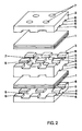
- two green bodies 1, as described above, are interposed between grooved graphite plates 2, 3 and 4, the graphite plates 2 and 4 being grooved only on the side facing the green body 1, while the graphite plate 3 has a grooved surface on the top and bottom.
- the grooves 5 are designed in two mutually perpendicular directions in such a way that elevations 6 are formed in each case, which form the contact surfaces for the green body 1.
- the grooves 5 serve to remove gases occurring during the pyrolysis.
- additional holes 7 can also be provided.
- the mass of the upper graphite plate 2 was 10 kg
- the mass of the middle graphite plate 3 was also 10 kg.
- the pyrolysis cycle is maintained under a nitrogen purge while maintaining a Rate started from 30 l / min.
- a temperature profile is set in the furnace, as shown in Figure 3.
- the individual durations of the Heating sections can be seen directly in FIG. 3, the lower one (in Parenthesized range of numbers shows the possible range of variation during the upper value represents the preferred heating rate).
- the second heating level is so long carried out until a conversion of at least 70% of the polymer resin into carbon has taken place (in the example shown, this time period is approximately 39 Hours).
- the third heating phase there is a rapid heating from 570 ° C to 900 ° C, whereby 900 ° C represents the maximum pyrolysis temperature.
- the heating rate is about 100 ° C / h.
- time periods reference is again made to FIG. 3.
- rapid cooling from 900 ° C to room temperature with a cooling rate of 100 ° C / h, if necessary with forced cooling.
- the green body is now removed from the oven and a test is carried out in relation to it for porosity, density and larger defects (e.g. blowholes or delamination). Under Flaws cannot be determined if the parameters specified above are observed. If such delamination nevertheless occurs due to any irregularities Should this occur, this component is discarded.
- porosity, density and larger defects e.g. blowholes or delamination.
- the pyrolyzed green bodies taken from the oven, each have external dimensions of 288 mm x 288 mm x 14.3 mm.
- silicon becomes liquid in the pyrolyzed green body infiltrates.
- silicon in vapor form in the crack structure infiltrate the green body is also possible.
- the liquid silicon is infiltrated in a graphite trough with a diameter of 420 mm.
- the graphite trough is first coated with a boron nitride suspension, which is applied with a brush. Then the area of the green body (288 mm x 288 mm) is marked in the center of the coated graphite trough. 480 g of silicon granulate are then applied to this marked area in a uniformly thick layer. Then the pyrolyzed green body is placed on the surface covered with granules, whereupon a further 240 g of silicon granules are applied evenly to the green body.
- 720 g of silicon granulate are uniformly introduced into the graphite trough, which corresponds to 45 mass percent of the pyrolyzed green body.
- the granules have a grain size of up to 15 mm and an impurity of less than 9 ppm.
- the graphite trough is then covered with a graphite cover, which is also coated with boron nitride suspension. After the furnace has been closed, the air inside the graphite trough is extracted and flushed with nitrogen. A pressure of 10 -2 mbar is then set and maintained in the furnace chamber.
- heating to 900 ° C takes place in a first heating stage a heating rate of about 100 ° C / h. This first heating period will last for about 9 Hours. Then the heating rate is reduced to 60 ° C / h until then a temperature of 1650 ° C is reached, which is above the melting temperature of silicon. This temperature of 1650 ° C is then held for 4 hours, so that it is ensured that the liquid silicon from the top and the Bottom is infiltrated into the green body by capillary action. This is followed by a Cooling down at a cooling rate of around 100 ° C / h to room temperature.
- the component After Reaching a temperature of 50 ° C is flushed with nitrogen with adjustment of atmospheric pressure. The component is removed and shows an external dimension of 286 mm x 286 mm x 14 mm. The component then undergoes a quality control with regard to delamination, residual porosity and density by means of ultrasound and / or X-ray inspection.
- components are designed so that they are manufactured to final dimensions, for example brake discs or brake pads.
- the surface can be finished to a small extent using diamond saws, Drills or grinders.
Landscapes
- Chemical & Material Sciences (AREA)
- Engineering & Computer Science (AREA)
- Ceramic Engineering (AREA)
- Materials Engineering (AREA)
- Chemical Kinetics & Catalysis (AREA)
- Manufacturing & Machinery (AREA)
- Structural Engineering (AREA)
- Organic Chemistry (AREA)
- General Engineering & Computer Science (AREA)
- Composite Materials (AREA)
- Mechanical Engineering (AREA)
- Ceramic Products (AREA)
Applications Claiming Priority (2)
| Application Number | Priority Date | Filing Date | Title |
|---|---|---|---|
| DE19749462 | 1997-11-10 | ||
| DE19749462A DE19749462C1 (de) | 1997-11-10 | 1997-11-10 | Verfahren zur Herstellung eines mit Kohlenstoff-Fasern verstärkten, keramisierten Formkörpers und Verwendung eines solchen Formkörpers |
Publications (4)
| Publication Number | Publication Date |
|---|---|
| EP0915070A2 true EP0915070A2 (fr) | 1999-05-12 |
| EP0915070A3 EP0915070A3 (fr) | 1999-09-15 |
| EP0915070B1 EP0915070B1 (fr) | 2003-02-19 |
| EP0915070B8 EP0915070B8 (fr) | 2003-06-25 |
Family
ID=7848072
Family Applications (1)
| Application Number | Title | Priority Date | Filing Date |
|---|---|---|---|
| EP98119179A Expired - Lifetime EP0915070B8 (fr) | 1997-11-10 | 1998-10-10 | Procédé de fabrication d'un corps moulé céramifié et renforcé par fibres de carbone et l'utilisation d'un tel corps moulé |
Country Status (2)
| Country | Link |
|---|---|
| EP (1) | EP0915070B8 (fr) |
| DE (2) | DE19749462C1 (fr) |
Cited By (6)
| Publication number | Priority date | Publication date | Assignee | Title |
|---|---|---|---|---|
| EP1457769A3 (fr) * | 2003-03-03 | 2005-03-30 | TMD Friction Europe GmbH | Procédé de fabrication des garnitures de frein ou d'embayage |
| DE102010003212A1 (de) | 2009-04-01 | 2011-01-13 | Krenkel, Walter, Prof.Dr. | Verfahren zur Herstellung eines Bauteils aus einem Faserverbundwerkstoff |
| WO2011120598A1 (fr) | 2010-03-30 | 2011-10-06 | Rec Wafer Norway As | Procédé pour la production de lingots de silicium de qualité convenant pour la fabrication de semi-conducteurs, creusets réutilisables et leur procédé de fabrication |
| WO2012143867A1 (fr) | 2011-04-19 | 2012-10-26 | Rec Wafer Pte. Ltd. | Aménagement pour fabriquer des lingots de silicium cristallin |
| WO2012143385A1 (fr) | 2011-04-19 | 2012-10-26 | Rec Wafer Pte. Ltd. | Agencement pour fabriquer des lingots de silicium cristallin |
| US9435052B2 (en) | 2011-04-19 | 2016-09-06 | Rec Solar Pte. Ltd. | Arrangement for manufacturing crystalline silicon ingots |
Families Citing this family (8)
| Publication number | Priority date | Publication date | Assignee | Title |
|---|---|---|---|---|
| DE19944345A1 (de) | 1999-09-16 | 2001-03-22 | Sgl Technik Gmbh | Mit Fasern und/oder Faserbündeln verstärkter Verbundwerkstoff mit keramischer Matrix |
| US20040067316A1 (en) * | 2002-10-04 | 2004-04-08 | Paul Gray | Method for processing silicon-carbide materials using organic film formers |
| DE10359484A1 (de) * | 2003-12-18 | 2005-07-14 | Deutsches Zentrum für Luft- und Raumfahrt e.V. | Verfahren zur Herstellung eines Bauteils aus einem Faserverbundwerkstoff und Faserverbundwerkstoff |
| US7501370B2 (en) | 2004-01-06 | 2009-03-10 | Saint-Gobain Ceramics & Plastics, Inc. | High purity silicon carbide wafer boats |
| DE102005002633A1 (de) * | 2005-01-13 | 2006-07-20 | Deutsches Zentrum für Luft- und Raumfahrt e.V. | Verfahren und Vorrichtung zur Carbidbildner-Infiltration eines porösen kohlenstoffhaltigen Vorkörpers |
| GB0701849D0 (en) * | 2007-01-31 | 2007-03-14 | Surface Transforms Plc | Improvements in or relating to brake and clutch discs |
| TWI421965B (zh) | 2007-12-20 | 2014-01-01 | 聖高拜陶器塑膠公司 | 處理半導體製程元件之方法及其形成之元件 |
| DE102023136652A1 (de) | 2023-12-22 | 2025-06-26 | Cvt Gmbh & Co. Kg | Verfahren zum Flüssiginfiltrieren eines porösen Körpers mit einem flüssigen, Si-haltigen Material, Reib- oder Gleitkörper, der einen C/SiC-Körper oder einen SiC/SiC-Körper aufweist, herstellbar/hergestellt mit dem Verfahren und Verwendung eines Hilfskörpers, der einen Abschnitt aus pyrolytischem Bornitrid aufweist, in einem LSI-Verfahren |
Family Cites Families (2)
| Publication number | Priority date | Publication date | Assignee | Title |
|---|---|---|---|---|
| GB1457757A (en) * | 1973-11-28 | 1976-12-08 | Secr Defence | Carbon fibre/carbon composite materials impregnated with silicon |
| GB9525622D0 (en) * | 1995-12-15 | 1996-02-14 | Sab Wabco Bromborough Limited | Friction engaging device |
-
1997
- 1997-11-10 DE DE19749462A patent/DE19749462C1/de not_active Expired - Lifetime
-
1998
- 1998-10-10 EP EP98119179A patent/EP0915070B8/fr not_active Expired - Lifetime
- 1998-10-10 DE DE59807233T patent/DE59807233D1/de not_active Expired - Lifetime
Cited By (6)
| Publication number | Priority date | Publication date | Assignee | Title |
|---|---|---|---|---|
| EP1457769A3 (fr) * | 2003-03-03 | 2005-03-30 | TMD Friction Europe GmbH | Procédé de fabrication des garnitures de frein ou d'embayage |
| DE102010003212A1 (de) | 2009-04-01 | 2011-01-13 | Krenkel, Walter, Prof.Dr. | Verfahren zur Herstellung eines Bauteils aus einem Faserverbundwerkstoff |
| WO2011120598A1 (fr) | 2010-03-30 | 2011-10-06 | Rec Wafer Norway As | Procédé pour la production de lingots de silicium de qualité convenant pour la fabrication de semi-conducteurs, creusets réutilisables et leur procédé de fabrication |
| WO2012143867A1 (fr) | 2011-04-19 | 2012-10-26 | Rec Wafer Pte. Ltd. | Aménagement pour fabriquer des lingots de silicium cristallin |
| WO2012143385A1 (fr) | 2011-04-19 | 2012-10-26 | Rec Wafer Pte. Ltd. | Agencement pour fabriquer des lingots de silicium cristallin |
| US9435052B2 (en) | 2011-04-19 | 2016-09-06 | Rec Solar Pte. Ltd. | Arrangement for manufacturing crystalline silicon ingots |
Also Published As
| Publication number | Publication date |
|---|---|
| EP0915070B8 (fr) | 2003-06-25 |
| EP0915070A3 (fr) | 1999-09-15 |
| DE19749462C1 (de) | 1999-03-04 |
| EP0915070B1 (fr) | 2003-02-19 |
| DE59807233D1 (de) | 2003-03-27 |
Similar Documents
| Publication | Publication Date | Title |
|---|---|---|
| EP0915070B1 (fr) | Procédé de fabrication d'un corps moulé céramifié et renforcé par fibres de carbone et l'utilisation d'un tel corps moulé | |
| EP0827942B1 (fr) | Procédé pour lier permanent au moins deux éléments de construction dans un corps moulé | |
| DE102004009264B4 (de) | Herstellung eines Vorformlings durch Verstärken einer faserartigen Struktur und/oder Verbinden von faserartigen Strukturen untereinander und Anwendung bei der Herstellung von Teilen aus Verbundwerkstoff | |
| EP3640022B1 (fr) | Procédé de fabrication de préimprégnés pour la fabrication de composants céramiques renforcés par des fibres | |
| DE69837677T2 (de) | Faserverbundwerkstoff und verfahren zur herstellung | |
| DE19710105A1 (de) | Mit Graphitkurzfasern verstärkter Siliciumcarbidkörper | |
| DE2853397B2 (fr) | ||
| DE3211474A1 (de) | Geformte gegenstaende aus poroesem kohlenstoff | |
| DE102019215661A1 (de) | Keramische Faserverbundbauteile | |
| DE102015221111A1 (de) | Carbonfaserverstärktes carbidkeramisches Verbundbauteil | |
| DE3037199A1 (de) | Verfahren zum herstellen von formkoerpern aus siliziumkarbid oder formkoerpern aus graphit oder graphitaehnlichem werkstoff mit einer aus siliziumkarbid bestehenden oberflaeche | |
| DE19947731B4 (de) | Verfahren zur Herstellung eines Bauteils aus SiC-Keramik sowie danach hergestelltes Halbzeug | |
| DE69806333T2 (de) | Faserverbundwerkstoff und seine Verwendung | |
| DE3413646A1 (de) | Undurchlaessige, kohlenstoffhaltige formkoerper und verfahren zu deren herstellung | |
| DE69112313T2 (de) | Poröser Filtermembranträger aus Kohlenstoff/Kohlenstoff-Verbundmaterial mit einem Fasermattensubstrat aus Kohlefaser und Verfahren zu seiner Herstellung. | |
| DE10014418A1 (de) | Faserverstärktes Strukturbauteil | |
| DE3131059A1 (de) | Verfahren zur herstellung von kohlenstoffaserverstaerkten kohlenstoffverbundmaterialien | |
| DE102007053498A1 (de) | Verfahren zur Herstellung von Reibscheiben aus faserverstärkten keramischen Werkstoffen | |
| EP1505310A2 (fr) | Procédé de fabrication d'un matériau de friction à base de tissu de fibres de carbone et matériau obtenu selon ce procédé | |
| EP2192096A2 (fr) | Procédé de fabrication d'un composant en céramique | |
| EP1876158B1 (fr) | Procédé destiné à la fabrication de composants carbocéramiques | |
| EP1515835A1 (fr) | Corps carbone en nid d'abeilles | |
| DE102019005913A1 (de) | Verfahren und Vorrichtung zum Herstellen eines Bauteils aus einem Faserverbundwerkstoff | |
| DE4034915C2 (fr) | ||
| DE69127900T2 (de) | Kohlenstoff-kohlenstoff verbundmaterial |
Legal Events
| Date | Code | Title | Description |
|---|---|---|---|
| PUAI | Public reference made under article 153(3) epc to a published international application that has entered the european phase |
Free format text: ORIGINAL CODE: 0009012 |
|
| AK | Designated contracting states |
Kind code of ref document: A2 Designated state(s): DE FR GB IT |
|
| AX | Request for extension of the european patent |
Free format text: AL;LT;LV;MK;RO;SI |
|
| PUAL | Search report despatched |
Free format text: ORIGINAL CODE: 0009013 |
|
| 17P | Request for examination filed |
Effective date: 19990601 |
|
| AK | Designated contracting states |
Kind code of ref document: A3 Designated state(s): AT BE CH CY DE DK ES FI FR GB GR IE IT LI LU MC NL PT SE |
|
| AX | Request for extension of the european patent |
Free format text: AL;LT;LV;MK;RO;SI |
|
| AKX | Designation fees paid |
Free format text: DE FR GB IT |
|
| 17Q | First examination report despatched |
Effective date: 20010820 |
|
| GRAG | Despatch of communication of intention to grant |
Free format text: ORIGINAL CODE: EPIDOS AGRA |
|
| GRAG | Despatch of communication of intention to grant |
Free format text: ORIGINAL CODE: EPIDOS AGRA |
|
| GRAH | Despatch of communication of intention to grant a patent |
Free format text: ORIGINAL CODE: EPIDOS IGRA |
|
| GRAH | Despatch of communication of intention to grant a patent |
Free format text: ORIGINAL CODE: EPIDOS IGRA |
|
| GRAA | (expected) grant |
Free format text: ORIGINAL CODE: 0009210 |
|
| AK | Designated contracting states |
Designated state(s): DE FR GB IT |
|
| REG | Reference to a national code |
Ref country code: GB Ref legal event code: FG4D Free format text: NOT ENGLISH |
|
| REF | Corresponds to: |
Ref document number: 59807233 Country of ref document: DE Date of ref document: 20030327 Kind code of ref document: P |
|
| GBT | Gb: translation of ep patent filed (gb section 77(6)(a)/1977) |
Effective date: 20030415 |
|
| RBV | Designated contracting states (corrected) |
Designated state(s): FR GB IT |
|
| ET | Fr: translation filed | ||
| PLBE | No opposition filed within time limit |
Free format text: ORIGINAL CODE: 0009261 |
|
| STAA | Information on the status of an ep patent application or granted ep patent |
Free format text: STATUS: NO OPPOSITION FILED WITHIN TIME LIMIT |
|
| 26N | No opposition filed |
Effective date: 20031120 |
|
| REG | Reference to a national code |
Ref country code: FR Ref legal event code: PLFP Year of fee payment: 19 |
|
| REG | Reference to a national code |
Ref country code: FR Ref legal event code: PLFP Year of fee payment: 20 |
|
| PGFP | Annual fee paid to national office [announced via postgrant information from national office to epo] |
Ref country code: FR Payment date: 20170922 Year of fee payment: 20 Ref country code: GB Payment date: 20170925 Year of fee payment: 20 |
|
| PGFP | Annual fee paid to national office [announced via postgrant information from national office to epo] |
Ref country code: IT Payment date: 20171016 Year of fee payment: 20 |
|
| REG | Reference to a national code |
Ref country code: GB Ref legal event code: PE20 Expiry date: 20181009 |
|
| PG25 | Lapsed in a contracting state [announced via postgrant information from national office to epo] |
Ref country code: GB Free format text: LAPSE BECAUSE OF EXPIRATION OF PROTECTION Effective date: 20181009 |