EP0915210A2 - Soupape d'évacuation pour réservoirs de chasse - Google Patents
Soupape d'évacuation pour réservoirs de chasse Download PDFInfo
- Publication number
- EP0915210A2 EP0915210A2 EP98120768A EP98120768A EP0915210A2 EP 0915210 A2 EP0915210 A2 EP 0915210A2 EP 98120768 A EP98120768 A EP 98120768A EP 98120768 A EP98120768 A EP 98120768A EP 0915210 A2 EP0915210 A2 EP 0915210A2
- Authority
- EP
- European Patent Office
- Prior art keywords
- float
- overflow pipe
- drain fitting
- fitting according
- bottom valve
- Prior art date
- Legal status (The legal status is an assumption and is not a legal conclusion. Google has not performed a legal analysis and makes no representation as to the accuracy of the status listed.)
- Granted
Links
- 238000011010 flushing procedure Methods 0.000 title claims abstract description 22
- XLYOFNOQVPJJNP-UHFFFAOYSA-N water Substances O XLYOFNOQVPJJNP-UHFFFAOYSA-N 0.000 claims description 19
- 238000000034 method Methods 0.000 claims description 18
- 230000033001 locomotion Effects 0.000 claims description 6
- 210000000078 claw Anatomy 0.000 claims description 5
- 239000011324 bead Substances 0.000 claims description 3
- 230000005484 gravity Effects 0.000 claims description 2
- 230000026058 directional locomotion Effects 0.000 claims 1
- 239000008237 rinsing water Substances 0.000 description 4
- 230000000977 initiatory effect Effects 0.000 description 1
- 238000009434 installation Methods 0.000 description 1
- 238000009420 retrofitting Methods 0.000 description 1
- 230000000630 rising effect Effects 0.000 description 1
- 238000007789 sealing Methods 0.000 description 1
- 230000001960 triggered effect Effects 0.000 description 1
- 238000005406 washing Methods 0.000 description 1
Images


Classifications
-
- E—FIXED CONSTRUCTIONS
- E03—WATER SUPPLY; SEWERAGE
- E03D—WATER-CLOSETS OR URINALS WITH FLUSHING DEVICES; FLUSHING VALVES THEREFOR
- E03D1/00—Water flushing devices with cisterns ; Setting up a range of flushing devices or water-closets; Combinations of several flushing devices
- E03D1/02—High-level flushing systems
- E03D1/14—Cisterns discharging variable quantities of water also cisterns with bell siphons in combination with flushing valves
- E03D1/142—Cisterns discharging variable quantities of water also cisterns with bell siphons in combination with flushing valves in cisterns with flushing valves
- E03D1/144—Cisterns discharging variable quantities of water also cisterns with bell siphons in combination with flushing valves in cisterns with flushing valves having a single flush outlet and an additional float for delaying the valve closure
Definitions
- the invention relates to a drain fitting for a cistern, comprising a bottom valve, an overflow pipe with the bottom valve closure member, a lifting device for opening the bottom valve and a hold-open device for the bottom valve during the emptying process.
- a drain fitting for a cistern comprising a bottom valve, an overflow pipe with the bottom valve closure member, a lifting device for opening the bottom valve and a hold-open device for the bottom valve during the emptying process.
- Such devices are known.
- the invention has for its object a compact built drain valve with a push button for a full and partial rinse option.
- This object is achieved according to the invention in a generic Drain fitting solved in that the lifting device arranged essentially in the overflow pipe and a float-controlled locking device for keeping open the bottom valve provided during the emptying process is, the locking device of a first float is controlled for a full flush alone while for a partial rinse a second float can be activated above the first float, which is used for Completion of the partial rinse for the first float Solution of the locking device acts.
- the outlet fitting can be made compact, so that simple installation in the various cisterns is made possible.
- a retrofitting of a cistern with the outlet fitting according to the invention can also be carried out in a simple manner.
- the proposed outlet fitting enables a switchover to a partial flush after a full flush has been initiated by actuating a second trigger. But even after a partial rinse has been carried out, the partial rinsing process can be continued into a full rinsing process by actuating a push button.
- the arrangement of the floats in the outlet fitting allows a relatively large setting range, so that the amounts of water required for a partial rinsing process and a full rinsing process can be set accordingly in a wide variety of water tanks.
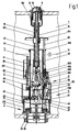
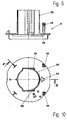
- the outlet fitting is arranged in a cistern 1, which is only shown schematically and in part, the water inlet device not being shown.
- An outlet opening is formed in the bottom region, in which a bottom valve 2 is arranged in a sealed manner in a known manner.
- the flushing line is connected to the outlet connection 20 formed on the bottom valve 2 (not shown in the drawing).
- the bottom valve 2 is formed with a collar 21 with an enlarged diameter, in the side wall of which water inlet slots 210 are arranged.
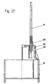
- an overflow pipe 3 Arranged coaxially to the bottom valve 2 is an overflow pipe 3 which carries at the lower end region a closure member 31 which is designed in the manner of an annular flange and on which a sealing ring 310 is attached with the aid of a support ring 33 such that the overflow pipe 3 blocks the outflow into the outlet connection 20 in the lowered position .
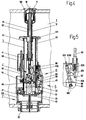
- a lifting device 4 is arranged essentially coaxially to the overflow pipe 3 in the interior of the overflow pipe 3. In the lower area, the lifting device 4 is held concentrically in the connecting piece 20 with an attachment. On the opposite side, the lifting device 4 has a sleeve 41 with an internal thread, in which a holding tube 12 with a continuous longitudinal slot 121 is arranged.
- a pusher housing 100 is screwed on, which bears against the outside of a lid of the cistern 1 and holds it in the closed position.
- a first large-area handle 10 is provided, in which a second small-area handle 11 is arranged.
- the first pusher 10 is connected to the lifting device 4 by a linkage 42.
- the second pusher 11 is connected via a pressure tube 61 which is arranged coaxially to the linkage 42 in the holding tube 12 and which carries at the lower end region an annular flange 611 arranged above the overflow tube 3, against which a plunger 62 pressed by a return spring 620 bears.
- the ring flange 611 is connected to the pressure pipe 61 via a radial shoulder 610, as can be seen in particular from FIG. 34.
- the pressure tube 61 is inserted axially into the holding tube 12, the radial shoulder 610 reaching through the longitudinal slot 121, while the ring flange 611 has a free annular space 612, through which the holding tube 12 extends.
- the lifting device 4 coaxially carries in the area of the sleeve 41 a guide piece 45 which is arranged axially displaceably in a support body 47 of the lifting device 4 and is pressed by a return spring 451 against the lower end face of the linkage 42.
- two opposite two-armed levers 46 are arranged, each of which is connected on the one hand to the guide piece 45 via a connecting rod-like tab 450, while the other side of the lever 46 is connected to an extension of a claw 40.
- the two claws 40 are also elastically connected to one another via ring-shaped spring elements.
- the claws 40 are arranged in the region of a circumferential inner bead 30 of the overflow pipe 3.
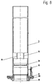
- a plate disk 43 is formed on the support body 47, with which rising of the rinsing water in the overflow pipe 3 is largely prevented.
- a locking lug 32 is formed radially and parallel to the central axis, which cooperates with a locking device 5.
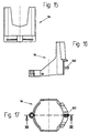
- the locking device 5 is bounded by a base plate 51 arranged on the collar 21 with a guide bush 510 and a cap 63 forming an outer jacket, a first float 50 being arranged in the annular space formed therein.
- the float 50 is semicircular and carries two opposite bearing journals 502 on the edge in the region of the latching lug 32, by means of which it is pivotably received by bearings 511 arranged on the base plate 51.
- a pawl 500 is formed on the float 50 in the area of the detent 32.
- the float 50 has a stop 501 at the end regions of the circular ring piece.
- an opening 512 is formed in the base plate 51, through which the locking lug 32 can be inserted into the locking device 5.
- an outlet slot 632 is also formed on the cap 63, with which the rate of emptying of the water collected between the cap 63 and the base plate 51 can be adjusted with the aid of a rotary valve (not shown in the drawing).
- radially projecting ribs 35 are formed, which in corresponding recesses 513 on the guide bush 510 and thus a rotational axial movement ensure the overflow pipe 3.
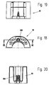
- a partial flushing device 6 arranged in a shoulder 630 of the cap 63 .
- a second swimmer 60 semicircular and with one Snap device 600 adjustable in height on a rod 65 connected with a bridge 64.
- the swimmer 60 encompasses half of the overflow pipe 3 on the Float 50 opposite side.
- the bridge 64 On the pole 65 opposite side, the bridge 64 carries one laterally protruding journal 640 on which a Control lever 66 with an eye bearing 662 pivotable is attached.
- the eye bearing 662 has one Radial slot 6620 so that the control lever 66 is radial can be snapped open on the bearing pin 640 can.
- the Control lever 66 with one pointing away from the overflow pipe 3 Control pin 660 provided in one in the Approach 630 trained control groove 631.
- the Control groove 631 has a rest position 6310 for the Control lever 66 in which the partial flushing device 6 is out of order.
- the control groove 631 has different Depths with the help of a control lever 66 provided spring element, which is in the form of a first straight leaf spring 663 facing the control groove 631 and a second leaf spring facing the overflow pipe 3 664 formed from approximately circular arc-shaped training is felt by the control pin 660.
- Furthermore has the control lever 66 in the central region an inclined surface 661 with an end face of the Plunger 62 cooperates.
- the plunger 62 is on the one hand in the approach 630 and on the other hand in a guide hole 340 of a non-positively held on the overflow pipe 3 Guide ring 34 stored.
- the drain fitting described above works as follows: In Fig. 1 of the drawing, the outlet fitting is in the rest position, the bottom valve 2 being closed and the cistern 1 being filled to the maximum with flushing water 13. If the user now presses the first pusher 10 into the pusher housing 100, as shown in FIGS. 2 and 3 of the drawing, the following actions take place: The linkage 42 pushes the guide piece 45 into the supporting body 47 of the lifting device 4, as a result of which the sliding movement is transmitted to the two adjusting levers 46 from the tabs 450.
- the levers 46 reverse the direction of movement and thereby pull up the overflow pipe 3 from the bottom valve 2 with the claws 40 which bear against the inner bead 30 of the overflow pipe 3, after which the catch 32 engages through the opening 512 behind the pawl 500 of the float 50 and the overflow pipe 3 is locked in this position, so that the bottom valve 2 remains in the open position and the flushing water 13 is discharged from the cistern 1 via the outlet connection 20.
- the float 50 is hereby brought into an inclined position by the one-sided mounting due to the buoyancy and holds the detent 32 in this position with the pawl 500.
- the pressure pipe 61 with the ring flange 611 is axially displaced in the direction of the bottom valve 2 via the second pusher 11, so that the plunger 62 comes against the force of the return spring 620 with its end region against the inclined surface 661 and the control lever 66 with its Control pin 660 laterally deflected from the rest position 6310 in the control groove 631, as can be seen in particular from FIG. 5.
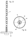
- the control pin 660 is displaced axially via the two leaf springs 663, 644 and reaches the area E to F, as can be seen in particular from FIGS. 25 and 26.
- the partial flushing device is hereby activated, the control lever 66 being connected to the second float 60 via the bridge 64 and the rod 65, so that the level of the bridge 64 is now determined by the float 60.
- the control lever 66 being connected to the second float 60 via the bridge 64 and the rod 65, so that the level of the bridge 64 is now determined by the float 60.
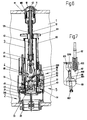
- FIGS. 6 and 7 after the user has released the pushers 10 and 11, they return to their starting position while the rinsing water flows out via the outlet connection 20.
- the level of the flushing water in the cistern 1 drops, so that the second float 60 with the bridge 64 and the control lever 66 guided with the control pin 660 in the control groove 631 drops correspondingly downward.
- the control pin 660 thereby moves from the area F to the area A, an axial jump preventing the control pin 660 from being able to be returned to the area F (cf.
- FIGS. 25 and 26 As soon as the level in the cistern 1 has dropped so far that the bridge 64 comes to rest against the stops 501 of the first float 50, the latter is separated from it by the weight of the second float 60, the rod 65, the bridge 64 and the actuating lever 66 Oblique position, counter to the buoyancy, returned to a horizontal position, so that the latch 32 is now released by the pawl 500 and the overflow pipe 3 with the closure member 31 falls back on the bottom valve 2 and shuts off the outlet connection 20 and thus ends the partial flushing process.
- the flushing water 13 is refilled in the cistern 1 by the filling device (not shown in the drawing), so that the bridge 64 with the control lever 66 rises accordingly from the float over the rod 65, the control pin 660 moving from area A into the Area B, in the area C, D, E ,, namely the rest position 6310, is returned.
- the drain fitting is therefore again in the same initial situation as that shown in FIG. 1 of the drawing and is ready for a new full or partial flushing process.
- the amount of rinsing water that is to be dispensed with a partial rinsing process can be adjusted over a wide range by adjusting the second float 60 with the snap device 600 on the rod 65.
- the second pusher 11 should be provided with a relatively small actuation area, so that either the pusher 10, 11 or only the first pusher 10 is actuated when the flushing process is initiated.
Landscapes
- Life Sciences & Earth Sciences (AREA)
- Engineering & Computer Science (AREA)
- Hydrology & Water Resources (AREA)
- Public Health (AREA)
- Water Supply & Treatment (AREA)
- Health & Medical Sciences (AREA)
- Sanitary Device For Flush Toilet (AREA)
- Float Valves (AREA)
- Mechanically-Actuated Valves (AREA)
- Loading And Unloading Of Fuel Tanks Or Ships (AREA)
- Fluid-Driven Valves (AREA)
- Other Liquid Machine Or Engine Such As Wave Power Use (AREA)
- Superconductors And Manufacturing Methods Therefor (AREA)
- Multiple-Way Valves (AREA)
Applications Claiming Priority (2)
| Application Number | Priority Date | Filing Date | Title |
|---|---|---|---|
| DE19748621 | 1997-11-04 | ||
| DE19748621A DE19748621A1 (de) | 1997-11-04 | 1997-11-04 | Ablaufventil für Spülkästen |
Publications (3)
| Publication Number | Publication Date |
|---|---|
| EP0915210A2 true EP0915210A2 (fr) | 1999-05-12 |
| EP0915210A3 EP0915210A3 (fr) | 1999-10-20 |
| EP0915210B1 EP0915210B1 (fr) | 2005-02-02 |
Family
ID=7847538
Family Applications (1)
| Application Number | Title | Priority Date | Filing Date |
|---|---|---|---|
| EP98120768A Expired - Lifetime EP0915210B1 (fr) | 1997-11-04 | 1998-11-02 | Soupape d'évacuation pour réservoirs de chasse |
Country Status (8)
| Country | Link |
|---|---|
| US (1) | US6094753A (fr) |
| EP (1) | EP0915210B1 (fr) |
| AT (1) | ATE288519T1 (fr) |
| AU (1) | AU746540B2 (fr) |
| BR (1) | BR9804410A (fr) |
| DE (2) | DE19748621A1 (fr) |
| ES (1) | ES2237817T3 (fr) |
| ZA (1) | ZA989732B (fr) |
Cited By (5)
| Publication number | Priority date | Publication date | Assignee | Title |
|---|---|---|---|---|
| FR2819835A1 (fr) | 2001-01-23 | 2002-07-26 | Sanitaire Accessoires Services | Mecanisme de chasse d'eau pour reservoir de toilettes |
| RU2416698C2 (ru) * | 2005-12-09 | 2011-04-20 | Оливейра Энд Ирмау, С.А. | Спускной клапан промывочного бака |
| RU2420633C2 (ru) * | 2005-12-09 | 2011-06-10 | Оливейра Энд Ирмау, С.А. | Сливной клапан смывного бачка с системой регулирования количества сливаемой воды |
| RU2434101C2 (ru) * | 2006-01-24 | 2011-11-20 | Санитэр Аксессуар Сервис С.А.С. | Гидравлическое исполнительное устройство |
| EP3900530A1 (fr) | 2020-04-23 | 2021-10-27 | Bayer AG | Gestion du liquide pour un dispositif d'arrêt |
Families Citing this family (20)
| Publication number | Priority date | Publication date | Assignee | Title |
|---|---|---|---|---|
| US6484327B2 (en) * | 2001-01-19 | 2002-11-26 | Douglas P. Hand | Toilet valve assembly |
| US20040064879A1 (en) * | 2002-01-18 | 2004-04-08 | Hand Douglas P. | Flush handles for dual flush-volume toilet system |
| US6728975B2 (en) | 2002-08-30 | 2004-05-04 | American Standard Inc. | High performance flush valve assembly |
| RU2250310C2 (ru) * | 2003-03-25 | 2005-04-20 | Ооо "Инкоэр" | Сливная арматура |
| FR2854180B1 (fr) | 2003-04-24 | 2005-07-01 | L T Aqua & | Mecanisme de chasse d'eau pour l'evacuation selective de differents volumes d'eau hors d'un quelconque reservoir |
| US20050091734A1 (en) * | 2003-11-05 | 2005-05-05 | Hand Douglas P. | Outflow valve assembly for a toilet tank |
| US20050097664A1 (en) * | 2003-11-10 | 2005-05-12 | Hand Douglas P. | Replaceable toilet valve lip |
| RU2283928C1 (ru) * | 2004-12-30 | 2006-09-20 | Ооо "Инкоэр" | Сливная арматура |
| DE102005020747A1 (de) | 2005-05-02 | 2006-11-09 | GROHEDAL Sanitärsysteme GmbH & Co. KG | Ablaufarmatur für einen Spülkasten |
| US7607635B2 (en) * | 2005-08-25 | 2009-10-27 | Sloan Valve Company | Flush valve handle assembly providing dual mode operation |
| AU2007217354B2 (en) | 2006-02-27 | 2011-03-31 | Sloan Valve Company | Dual flush activation |
| US20080022443A1 (en) * | 2006-07-31 | 2008-01-31 | Jones Ernest W | Toilet flush system |
| TWI390097B (zh) | 2006-09-29 | 2013-03-21 | Sloan Valve Co | 用於控制沖流閥或沖流計的沖流容積之方法及系統 |
| ATE483073T1 (de) * | 2007-05-25 | 2010-10-15 | Geberit Int Ag | Betätigungsvorrichtung für eine auslaufgarnitur und auslaufgarnitur mit einer solchen betätigungsvorrichtung sowie verfahren zum montieren einer solchen auslaufgarnitur |
| EP2006458B1 (fr) * | 2007-06-19 | 2015-07-22 | Geberit International AG | Clapet de sortie pour une chasse d'eau |
| PT2767639T (pt) * | 2013-02-15 | 2018-07-17 | Geberit Int Ag | Guarnição de descarga para um autoclismo |
| EP2813628B1 (fr) | 2013-03-15 | 2019-02-27 | Sloane Valve Company | Commande de chasse à double mode |
| EP2813627A1 (fr) | 2013-03-15 | 2014-12-17 | Sloan Valve Company | Actionneur de chasse d'eau automatique comprenant une commande manuelle additionelle |
| ES2773851T3 (es) * | 2013-10-28 | 2020-07-15 | Geberit Int Ag | Grifería de descarga para una cisterna |
| ES2570974T3 (es) * | 2013-10-28 | 2016-05-23 | Geberit Int Ag | Adaptador de desagüe para una cisterna de lavado |
Family Cites Families (8)
| Publication number | Priority date | Publication date | Assignee | Title |
|---|---|---|---|---|
| US4945581A (en) * | 1987-03-26 | 1990-08-07 | Harris John L | Flush tank water saver |
| FR2662194B1 (fr) * | 1990-05-17 | 1992-08-07 | Spmp Sa | Mecanisme de chasse interrompable, a ecoulement minimal assure. |
| EP0479716B1 (fr) * | 1990-08-29 | 1996-09-11 | Geberit AG | Dispositif d'actionnement d'un clapet de vidange d'un réservoir de chasse |
| DE4122394A1 (de) * | 1991-07-05 | 1993-01-07 | Heinrich Menge | Spuelvorrichtung |
| DE4302245A1 (en) * | 1992-02-03 | 1993-09-16 | Fong Chyi Chang | Actuating and control device for a water tank |
| FR2698645B1 (fr) * | 1992-12-01 | 1996-10-25 | Spmp | Mecanisme de chasse interrompable, a volume de vidange minimum conforme a l'hygiene. |
| FR2740795B1 (fr) * | 1995-11-03 | 1997-12-26 | Ragot Claude | Dispositif a double commande de face de reservoir d'eau |
| FR2744742A1 (fr) * | 1996-02-12 | 1997-08-14 | Piat Moise | Perfectionnement aux mecanismes de chasse a deux niveaux |
-
1997
- 1997-11-04 DE DE19748621A patent/DE19748621A1/de not_active Withdrawn
-
1998
- 1998-10-20 BR BR9804410-9A patent/BR9804410A/pt active Search and Examination
- 1998-10-21 US US09/176,162 patent/US6094753A/en not_active Expired - Fee Related
- 1998-10-26 ZA ZA989732A patent/ZA989732B/xx unknown
- 1998-11-02 AT AT98120768T patent/ATE288519T1/de not_active IP Right Cessation
- 1998-11-02 AU AU90483/98A patent/AU746540B2/en not_active Ceased
- 1998-11-02 EP EP98120768A patent/EP0915210B1/fr not_active Expired - Lifetime
- 1998-11-02 DE DE59812533T patent/DE59812533D1/de not_active Expired - Fee Related
- 1998-11-02 ES ES98120768T patent/ES2237817T3/es not_active Expired - Lifetime
Non-Patent Citations (1)
| Title |
|---|
| None |
Cited By (11)
| Publication number | Priority date | Publication date | Assignee | Title |
|---|---|---|---|---|
| FR2819835A1 (fr) | 2001-01-23 | 2002-07-26 | Sanitaire Accessoires Services | Mecanisme de chasse d'eau pour reservoir de toilettes |
| WO2002059431A1 (fr) * | 2001-01-23 | 2002-08-01 | Societe Etex De Recherches Techniques, S.E.R.T. | Mecanisme de chasse d'eau pour reservoir de toilettes |
| GB2390617A (en) * | 2001-01-23 | 2004-01-14 | Etex De Rech S Tech S E R T So | Flushing mechanism for toilet tank |
| GB2390617B (en) * | 2001-01-23 | 2004-08-18 | Etex De Rech S Tech S E R T So | Water flushing mechanism for a toilet water tank |
| US6920649B2 (en) | 2001-01-23 | 2005-07-26 | Societe Etex De Recherches Techniques, Sert | Flushing mechanism for toilet tank |
| CN1318706C (zh) * | 2001-01-23 | 2007-05-30 | 艾太克技术研究公司 | 卫生间水箱的冲水装置 |
| RU2416698C2 (ru) * | 2005-12-09 | 2011-04-20 | Оливейра Энд Ирмау, С.А. | Спускной клапан промывочного бака |
| RU2420633C2 (ru) * | 2005-12-09 | 2011-06-10 | Оливейра Энд Ирмау, С.А. | Сливной клапан смывного бачка с системой регулирования количества сливаемой воды |
| RU2434101C2 (ru) * | 2006-01-24 | 2011-11-20 | Санитэр Аксессуар Сервис С.А.С. | Гидравлическое исполнительное устройство |
| EP3900530A1 (fr) | 2020-04-23 | 2021-10-27 | Bayer AG | Gestion du liquide pour un dispositif d'arrêt |
| WO2021213824A1 (fr) | 2020-04-23 | 2021-10-28 | Bayer Aktiengesellschaft | Gestion de fluide pour un dispositif de piégeage |
Also Published As
| Publication number | Publication date |
|---|---|
| AU9048398A (en) | 1999-05-27 |
| US6094753A (en) | 2000-08-01 |
| EP0915210A3 (fr) | 1999-10-20 |
| ES2237817T3 (es) | 2005-08-01 |
| BR9804410A (pt) | 2001-03-20 |
| DE59812533D1 (de) | 2005-03-10 |
| ATE288519T1 (de) | 2005-02-15 |
| AU746540B2 (en) | 2002-05-02 |
| ZA989732B (en) | 1999-05-04 |
| EP0915210B1 (fr) | 2005-02-02 |
| DE19748621A1 (de) | 1999-05-06 |
Similar Documents
| Publication | Publication Date | Title |
|---|---|---|
| EP0915210A2 (fr) | Soupape d'évacuation pour réservoirs de chasse | |
| EP0479716B1 (fr) | Dispositif d'actionnement d'un clapet de vidange d'un réservoir de chasse | |
| DE69227188T2 (de) | Spülwasseranlage zur Abgabe verschiedener, vorbestimmter Wassermengen | |
| DE29517363U1 (de) | Spüleinrichtung in einem WC-Spülkasten | |
| EP1719846B1 (fr) | Dispositif pour commande pneumatique d'une soupape d'écoulement | |
| DE69507951T2 (de) | Einlassventilmechanismus | |
| EP2141294B1 (fr) | Soupape à double volume pour une chasse d'eau dotée d'un mécanisme de flotteur à commande amélioré | |
| DE4226685C5 (de) | Überlaufarmatur für eine Bade- oder Duschwanne | |
| EP0915211A2 (fr) | Arrangement d'évacuation pour réservoir de chasse | |
| EP1028200A2 (fr) | Soupape d'échappement | |
| DE19715905B4 (de) | Vorrichtung zum Absperren des Zu- oder Ablaufrohres eines Leichtflüssigkeitsabscheiders | |
| DE2611604C2 (de) | Vorrichtung zur Begrenzung des Wasserauslaufes aus Wasserbehältern mit einem Bodenauslauf | |
| DE2100795A1 (de) | Vorrichtung zum dosierten Zuführen einer Flüssigkeit in ein Spülclosett | |
| DE361645C (de) | Mit Gegendruckkammer und Druckentlastungsventil versehenes Durchgangsventil | |
| EP0058823A1 (fr) | Réservoir de chasse d'eau | |
| DE2247282C3 (de) | Ablaufventil für einen Toilettenspülkasten | |
| DE3121625C2 (de) | Spülkasten zur Abgabe unterschiedlicher Spülwassermengen in sanitäre Einrichtungen, wie WC-Becken o.dgl. | |
| DE3305227A1 (de) | Becken mit steuervorrichtung zur ausloesung von regulier- und/oder schaltvorgaengen | |
| DE2544114A1 (de) | Vorrichtung zur aenderung der spuelwassermenge in wasserklosetts | |
| DE3811675A1 (de) | Einrichtung zum verhindern des oeffnens eines unter druck befindlichen dampfdruckkochtopfes | |
| DE19643537C2 (de) | Ablaufarmatur zum dosierten Teil- oder Vollabzug von Flüssigkeiten aus einem drucklosen Behälter | |
| DE69105268T2 (de) | Druckknopfspülmechanismus mit eintauchbarem Körper. | |
| DE593365C (de) | Mehrwegehahn, insbesondere fuer Fluessigkeitsfilterapparate mit Regeneriervorrichtung | |
| DE8105070U1 (de) | "toilettenspuelbecken" | |
| CH351237A (de) | Von Hand oder mit dem Knie betätigbares Ablaufventil für Waschbecken |
Legal Events
| Date | Code | Title | Description |
|---|---|---|---|
| PUAI | Public reference made under article 153(3) epc to a published international application that has entered the european phase |
Free format text: ORIGINAL CODE: 0009012 |
|
| AK | Designated contracting states |
Kind code of ref document: A2 Designated state(s): AT BE CH DE DK ES FI FR GB GR IE IT LI NL PT SE |
|
| AX | Request for extension of the european patent |
Free format text: AL;LT;LV;MK;RO;SI |
|
| PUAL | Search report despatched |
Free format text: ORIGINAL CODE: 0009013 |
|
| AK | Designated contracting states |
Kind code of ref document: A3 Designated state(s): AT BE CH CY DE DK ES FI FR GB GR IE IT LI LU MC NL PT SE |
|
| AX | Request for extension of the european patent |
Free format text: AL;LT;LV;MK;RO;SI |
|
| 17P | Request for examination filed |
Effective date: 20000317 |
|
| AKX | Designation fees paid |
Free format text: AT BE CH DE DK ES FI FR GB GR IE IT LI NL PT SE |
|
| RAP1 | Party data changed (applicant data changed or rights of an application transferred) |
Owner name: GROHEDAL GMBH & CO.KG |
|
| PUAJ | Public notification under rule 129 epc |
Free format text: ORIGINAL CODE: 0009425 |
|
| 17Q | First examination report despatched |
Effective date: 20030214 |
|
| 32PN | Public notification |
Free format text: BESCHEID GEMAESS ARTIKEL 96(2) VOM 14.02.2003 |
|
| RAP1 | Party data changed (applicant data changed or rights of an application transferred) |
Owner name: GROHEDAL SANITAERSYSTEME GMBH & CO.KG |
|
| GRAP | Despatch of communication of intention to grant a patent |
Free format text: ORIGINAL CODE: EPIDOSNIGR1 |
|
| GRAS | Grant fee paid |
Free format text: ORIGINAL CODE: EPIDOSNIGR3 |
|
| GRAA | (expected) grant |
Free format text: ORIGINAL CODE: 0009210 |
|
| AK | Designated contracting states |
Kind code of ref document: B1 Designated state(s): AT BE CH DE DK ES FI FR GB GR IE IT LI NL PT SE |
|
| PG25 | Lapsed in a contracting state [announced via postgrant information from national office to epo] |
Ref country code: IE Free format text: LAPSE BECAUSE OF FAILURE TO SUBMIT A TRANSLATION OF THE DESCRIPTION OR TO PAY THE FEE WITHIN THE PRESCRIBED TIME-LIMIT Effective date: 20050202 Ref country code: GB Free format text: LAPSE BECAUSE OF FAILURE TO SUBMIT A TRANSLATION OF THE DESCRIPTION OR TO PAY THE FEE WITHIN THE PRESCRIBED TIME-LIMIT Effective date: 20050202 Ref country code: FI Free format text: LAPSE BECAUSE OF FAILURE TO SUBMIT A TRANSLATION OF THE DESCRIPTION OR TO PAY THE FEE WITHIN THE PRESCRIBED TIME-LIMIT Effective date: 20050202 |
|
| REG | Reference to a national code |
Ref country code: GB Ref legal event code: FG4D Free format text: NOT ENGLISH |
|
| REG | Reference to a national code |
Ref country code: CH Ref legal event code: EP |
|
| REG | Reference to a national code |
Ref country code: IE Ref legal event code: FG4D Free format text: GERMAN |
|
| REF | Corresponds to: |
Ref document number: 59812533 Country of ref document: DE Date of ref document: 20050310 Kind code of ref document: P |
|
| PG25 | Lapsed in a contracting state [announced via postgrant information from national office to epo] |
Ref country code: SE Free format text: LAPSE BECAUSE OF FAILURE TO SUBMIT A TRANSLATION OF THE DESCRIPTION OR TO PAY THE FEE WITHIN THE PRESCRIBED TIME-LIMIT Effective date: 20050502 Ref country code: GR Free format text: LAPSE BECAUSE OF FAILURE TO SUBMIT A TRANSLATION OF THE DESCRIPTION OR TO PAY THE FEE WITHIN THE PRESCRIBED TIME-LIMIT Effective date: 20050502 Ref country code: DK Free format text: LAPSE BECAUSE OF FAILURE TO SUBMIT A TRANSLATION OF THE DESCRIPTION OR TO PAY THE FEE WITHIN THE PRESCRIBED TIME-LIMIT Effective date: 20050502 |
|
| REG | Reference to a national code |
Ref country code: CH Ref legal event code: NV Representative=s name: BOVARD AG PATENTANWAELTE |
|
| REG | Reference to a national code |
Ref country code: ES Ref legal event code: FG2A Ref document number: 2237817 Country of ref document: ES Kind code of ref document: T3 |
|
| GBV | Gb: ep patent (uk) treated as always having been void in accordance with gb section 77(7)/1977 [no translation filed] |
Effective date: 20050202 |
|
| REG | Reference to a national code |
Ref country code: IE Ref legal event code: FD4D |
|
| PGFP | Annual fee paid to national office [announced via postgrant information from national office to epo] |
Ref country code: NL Payment date: 20051031 Year of fee payment: 8 |
|
| PGFP | Annual fee paid to national office [announced via postgrant information from national office to epo] |
Ref country code: CH Payment date: 20051108 Year of fee payment: 8 |
|
| PGFP | Annual fee paid to national office [announced via postgrant information from national office to epo] |
Ref country code: DE Payment date: 20051123 Year of fee payment: 8 |
|
| PGFP | Annual fee paid to national office [announced via postgrant information from national office to epo] |
Ref country code: FR Payment date: 20051128 Year of fee payment: 8 Ref country code: AT Payment date: 20051128 Year of fee payment: 8 |
|
| PG25 | Lapsed in a contracting state [announced via postgrant information from national office to epo] |
Ref country code: BE Free format text: LAPSE BECAUSE OF NON-PAYMENT OF DUE FEES Effective date: 20051130 |
|
| PLBE | No opposition filed within time limit |
Free format text: ORIGINAL CODE: 0009261 |
|
| STAA | Information on the status of an ep patent application or granted ep patent |
Free format text: STATUS: NO OPPOSITION FILED WITHIN TIME LIMIT |
|
| PGFP | Annual fee paid to national office [announced via postgrant information from national office to epo] |
Ref country code: ES Payment date: 20051221 Year of fee payment: 8 |
|
| 26N | No opposition filed |
Effective date: 20051103 |
|
| ET | Fr: translation filed | ||
| PG25 | Lapsed in a contracting state [announced via postgrant information from national office to epo] |
Ref country code: AT Free format text: LAPSE BECAUSE OF NON-PAYMENT OF DUE FEES Effective date: 20061102 |
|
| PG25 | Lapsed in a contracting state [announced via postgrant information from national office to epo] |
Ref country code: LI Free format text: LAPSE BECAUSE OF NON-PAYMENT OF DUE FEES Effective date: 20061130 Ref country code: CH Free format text: LAPSE BECAUSE OF NON-PAYMENT OF DUE FEES Effective date: 20061130 |
|
| PGFP | Annual fee paid to national office [announced via postgrant information from national office to epo] |
Ref country code: IT Payment date: 20061130 Year of fee payment: 9 |
|
| PG25 | Lapsed in a contracting state [announced via postgrant information from national office to epo] |
Ref country code: NL Free format text: LAPSE BECAUSE OF NON-PAYMENT OF DUE FEES Effective date: 20070601 Ref country code: DE Free format text: LAPSE BECAUSE OF NON-PAYMENT OF DUE FEES Effective date: 20070601 |
|
| REG | Reference to a national code |
Ref country code: CH Ref legal event code: PL |
|
| NLV4 | Nl: lapsed or anulled due to non-payment of the annual fee |
Effective date: 20070601 |
|
| REG | Reference to a national code |
Ref country code: FR Ref legal event code: ST Effective date: 20070731 |
|
| BERE | Be: lapsed |
Owner name: GROHEDAL SANITARSYSTEME G.M.B.H. & CO.KG Effective date: 20051130 |
|
| PG25 | Lapsed in a contracting state [announced via postgrant information from national office to epo] |
Ref country code: PT Free format text: LAPSE BECAUSE OF NON-PAYMENT OF DUE FEES Effective date: 20050702 |
|
| REG | Reference to a national code |
Ref country code: ES Ref legal event code: FD2A Effective date: 20061103 |
|
| PG25 | Lapsed in a contracting state [announced via postgrant information from national office to epo] |
Ref country code: FR Free format text: LAPSE BECAUSE OF NON-PAYMENT OF DUE FEES Effective date: 20061130 Ref country code: ES Free format text: LAPSE BECAUSE OF NON-PAYMENT OF DUE FEES Effective date: 20061103 |
|
| PG25 | Lapsed in a contracting state [announced via postgrant information from national office to epo] |
Ref country code: IT Free format text: LAPSE BECAUSE OF NON-PAYMENT OF DUE FEES Effective date: 20071102 |