EP0915212A2 - Elément de toiture pour la fabrication d'une toiture de bâtiment - Google Patents
Elément de toiture pour la fabrication d'une toiture de bâtiment Download PDFInfo
- Publication number
- EP0915212A2 EP0915212A2 EP98118868A EP98118868A EP0915212A2 EP 0915212 A2 EP0915212 A2 EP 0915212A2 EP 98118868 A EP98118868 A EP 98118868A EP 98118868 A EP98118868 A EP 98118868A EP 0915212 A2 EP0915212 A2 EP 0915212A2
- Authority
- EP
- European Patent Office
- Prior art keywords
- roof element
- roof
- rafters
- element according
- ridge
- Prior art date
- Legal status (The legal status is an assumption and is not a legal conclusion. Google has not performed a legal analysis and makes no representation as to the accuracy of the status listed.)
- Withdrawn
Links
- 230000004888 barrier function Effects 0.000 claims description 25
- 238000009415 formwork Methods 0.000 claims description 17
- 238000007789 sealing Methods 0.000 claims description 9
- 238000009413 insulation Methods 0.000 claims description 7
- 230000000284 resting effect Effects 0.000 claims 1
- 239000000725 suspension Substances 0.000 claims 1
- 238000009416 shuttering Methods 0.000 abstract 1
- 238000010276 construction Methods 0.000 description 7
- 239000012528 membrane Substances 0.000 description 4
- 238000000034 method Methods 0.000 description 4
- 238000004519 manufacturing process Methods 0.000 description 3
- 229920006300 shrink film Polymers 0.000 description 2
- 241001459819 Carassius gibelio Species 0.000 description 1
- 239000010426 asphalt Substances 0.000 description 1
- 239000011324 bead Substances 0.000 description 1
- 239000011093 chipboard Substances 0.000 description 1
- 230000036461 convulsion Effects 0.000 description 1
- 238000009826 distribution Methods 0.000 description 1
- 238000005553 drilling Methods 0.000 description 1
- 230000005484 gravity Effects 0.000 description 1
- 238000011900 installation process Methods 0.000 description 1
- 238000005304 joining Methods 0.000 description 1
- 239000002557 mineral fiber Substances 0.000 description 1
- 230000035515 penetration Effects 0.000 description 1
- 238000009417 prefabrication Methods 0.000 description 1
- PQTBTIFWAXVEPB-UHFFFAOYSA-N sulcotrione Chemical compound ClC1=CC(S(=O)(=O)C)=CC=C1C(=O)C1C(=O)CCCC1=O PQTBTIFWAXVEPB-UHFFFAOYSA-N 0.000 description 1
- 239000002023 wood Substances 0.000 description 1
Images


Classifications
-
- E—FIXED CONSTRUCTIONS
- E04—BUILDING
- E04B—GENERAL BUILDING CONSTRUCTIONS; WALLS, e.g. PARTITIONS; ROOFS; FLOORS; CEILINGS; INSULATION OR OTHER PROTECTION OF BUILDINGS
- E04B7/00—Roofs; Roof construction with regard to insulation
- E04B7/20—Roofs consisting of self-supporting slabs, e.g. able to be loaded
- E04B7/22—Roofs consisting of self-supporting slabs, e.g. able to be loaded the slabs having insulating properties, e.g. laminated with layers of insulating material
- E04B7/225—Roofs consisting of self-supporting slabs, e.g. able to be loaded the slabs having insulating properties, e.g. laminated with layers of insulating material the slabs having non-structural supports for roofing materials
Definitions
- the invention relates to a roof element for manufacture a house roof made up of several in the longitudinal direction of the ridge connected roof elements with the characteristics according to the preamble of claim 1.
- Roof elements of the type mentioned above are known (DE magazine mikado 9/97; EP-A 775 787). You are ready in Prefabricated work that by joining the Substructure of a house roof very largely completed can be. This can reduce construction time and costs be reduced. It is also proposed that Hanging roof elements in pairs using a crane to raise and put on, provided they are for the two opposite roof sides of a gable roof determined are, or by means of individual roof elements To couple hinge joints to each other (EP-A 775 787). First after the manufacture of the roof substructure by means of roofing elements of this type can be used for roofing work be carried out, provided the house roof with roof tiles to be covered.
- Roofing work makes up a significant part of that the total work required to manufacture a house roof from and is also essential in its implementation Depending on weather conditions.
- the invention is therefore the Task based on the modular structure of a House roof by means of roof elements possible reduction of To increase construction time and construction costs even further.
- the invention according to the characterizing part of the claim 1 before that each roof element already in the roof tiles covered condition.
- roof tiles in particular interlocking roof tiles, already in Framework of prefabrication of a roof element on this in to lay conventionally without slipping or even a loss of roof tiles during transport or to fear when lifting and putting on the roof element if these processes are in one position or orientation of the roof element, where the intended roof inclination not exceeded and the roof tiles like a storm protection are secured.
- interlocking roof tiles behave due to their positive locking with each other and with the Battens of the roof element like a plate-like unit, so that it is sufficient the roof tiles, in particular ridge connection roof tiles and verge roof tiles, by means of Secure storm clips, as is the case with conventional ones Coverage work in wind-prone areas required is.
- the connecting edges on which the individual roof elements or put together after placing on the purlins are critical for the tightness of the house roof Put.
- the Roof elements covered with roof tiles in such a way that the one connecting edge to the next
- the rafters forming the roof element are kept free of roof tiles is.
- the width of the reserved area is on the connecting edge of two roof elements to be joined together so coordinated that after the mutual connection of the Roof elements only one missing in the direction of the eaves Row of roof tiles is still to be covered. in the Area of these connecting edges, it is also appropriate to at least two predetermined positions of the edge To provide rafters lifting loops.
- the one required for handling the roof element Rigidity is ensured by the rafters connected to each other by at least one formwork are either on the top or bottom of the Rafters is attached.
- Roof element whose underside with a vapor barrier layer covered by which the existing between the rafters Thermal insulation against the ingress of moisture from the Interior is protected.
- This arrangement of Vapor barrier layer already in the factory on the roof element opens up the possibility of an easier connection with adjoining parts of the house and consequently one more secure sealing of the thermal insulation than this for conventional house construction is possible. Because the Vapor barrier layer is applied from the outset jammed between the rafters and the purlins and therefore does not need to be sealed separately.
- the vapor barrier layer on the ridge side enclose the roof element, so that this also from above the thermal insulation is protected against moisture.
- the ridge-side edge of the Roof element completed by a ridge board, on the The vapor layer can be attached to the inside or outside surface can.
- the ridge board is advantageously like this aligned that it is in the attached state of the Roof element with its surface is vertical.
- the ridge board - in conjunction with the if necessary existing corresponding ridge board of the opposite roof element - replace the ridge batten, on which the ridge tiles to be retrofitted are to be fastened.
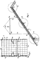
- the saddle house roof partially shown in Fig. 1 is constructed by roof elements 1 according to the invention, which itself from a ridge purlin 2 to an eaves purlin 3 extend and approximately in its longitudinal center by a Middle purlin 4 are supported.
- Each roof element 1 of the Embodiment has four equally spaced arranged rafters 10, two of which edge rafters only about half the cross section of the have intermediate rafters 10. All rafters are 10 by means of a formwork 11 on the top side connected, for example, by one or more Wood chipboard (OSB board) with a thickness of 18 mm is formed.
- OSB board Wood chipboard
- the formwork 11 is one breathable roof membrane or sarking membrane 12 covered, which can be a PE film or made of Bitumen plates exist and by means of counter battens 13 the casing 11 is fixed.
- the counter battens 13 carries a battens 14 extending in the ridge direction and on this is a roof tile covering 15 Interlocking roof tiles (Fig. 6).
- Between the rafters 10 is a thermal insulation layer 16 made of mineral fiber arranged protected by a vapor barrier layer 17 from below and is held.
- the vapor barrier layer 17 can also be a PE film and is on the rafters 10 by one in their Longitudinal air battens 18 fixed. From the drawings, the air battens 18 attached inner panel 19 is not part of a Roof element 1, but only applied subsequently.
- the Purlins 2, 3 and 4 assigned places to the bottom of the Rafters 10 have triangular recesses 21, 31 in cross section or 41 provided. They reach into these recesses Purlins 2, 3 and 4 form-fitting and hold over the 10 rafters each roof element 1. Between the Purlins 2 and 4 and the recesses 21 and 41 are here loose wooden intermediate layers 21 'or 41' arranged so that the Vapor barrier layer 17 thereby directly into the Recesses 21, 41 is pressed. Through the wooden liners can damage the vapor barrier 17 with relative movements between the roof element 1 and the Purlins 2, 4 can be avoided during the placement process.
- Vapor barrier layer 17 between the rafters 10 and the wooden intermediate layers 21 'and 41' or the purlins 2 and 4 in Area of the recesses 21, 41 clamped and thereby held.
- the vapor barrier layer 17 also extends around the ridge-side edge of the roof element 1 and is hit back on the top of the casing 11.
- the vapor barrier layer 17 runs along the inner surface of the Ridge boards 20.
- the ridge boards 20 lying one against the other of the two roof elements abutting on the ridge 1 can be connected and form with your The top edge of a ridge, on the usual way (not shown) ridge tiles 22 to be subsequently attached can be.
- Fig. 2 shows the roof element 1 in plan view in the Condition in which it is in transport and in the Put on the purlins 2, 3 and 4.
- the roofing 15 made of interlocking roof tiles is only schematic indicated, the cover beads of the interlocking roof tiles in each case - In Fig. 2 - lie to the right and to the left of it the side folds 150 are arranged.
- On the - in Fig. 2 - left side of the roof element 1, which is there through the rafters 10 with a smaller cross-section is over the whole Height of the roof element 1 is an edge area with a width A. kept free of interlocking roof tiles 15. Accordingly is on the - in Fig.
- rafters 10 are approximately midway between those formed by the purlins 2, 3 and 4 Fields lifting straps 30 attached; is in their area additionally from the subsequent row of interlocking roof tiles 15 each one folded roof tile omitted, so that each an access area 23 is created. This will prevents the handling of the roof element 1 by device attacking the lifting loops 30 Folded roof tile is moved or damaged.
- the cross members 32 are in turn with a support beam 33 rigidly connected so that the total Carrier has the shape of an I.
- At both ends of the Support beam 33 reach with a crane hook to be connected Ropes 34 on.
- FIGS. 6 and 7 is on the - in the Drawing - left side of the roof element 1 above the roofing membrane 12 a board or a crossbar 130 of the Counter battens 13 attached to the formwork 11 so that it protrudes beyond the formwork edge and thereby a shoulder 131 with the formwork 11 or the one below it following rafters 10 forms.
- the vapor barrier layer 17 is over the outer side surface of this rafter 10 to below shoulder 131 pulled up, at its angle to the outside kinked so that it is on the lower shoulder surface and along the outer surface of the board 130 fixed.
- the adjacent roof element 1 On the adjacent roof element 1 is one of them Batten 130a of the counter battens assigned to the connecting edge of which through the formwork 11 and the rafters 10 formed edge reset, so that a Cover area 132 created for shoulder 131 is.
- the vapor barrier layer is also on this roof element 17 on the outer side surface of the rafters 10 and over the Side edge of the formwork 11 pulled up on the Formwork 11 in cover area 132 turned over and fixed to the side surface of the slat 130a.
- FIG. 8 the practical embodiment according to FIG. 7 is pure schematically represented by the vapor barrier 17 to achieve sealing construction.
- Fig. 8 are between those involved in the sealing construction Components drawn to illustrate distances that not in practice or at least not in this Ratio exist. From the illustration it follows that that between the top of the overlap area 132 folded vapor barrier layer 17 and the bottom of the vapor barrier layer 17 of the a sealing tape or strip 133 adjacent to the roof element is arranged.
- the sealing tape 133 can either from be provided in advance on the roof element 1 or also only when the roof element is put in place Cover area 132 placed on the vapor barrier layer or be glued on.
- the roof elements 1 are in a horizontal position by the factory transported to the construction site so that the interlocking roof tile covering 15 can not slip.
- the placement process which is indicated in Fig. 1, takes place expediently in an inclined orientation of the Roof element 1, which is largely or completely the corresponds to the intended roof pitch.
- the Connecting cables 31 on the carrying device 32, 33 in length dimensioned so that the corresponding inclination of the roof element 1 can set itself when lifting by the crane.
- the attachment points of the lifting loops 30 so determined that it is the center of gravity of the roof element 1 between themselves and taking into account the Weight distribution have appropriate distances from it.
- interlocking roof tiles 15 of the roof element 1 are not shown storm brackets secured in the manner necessary for Storm protection of a roof tile covering is common.
- every third interlocking roof tile 15 is through a storm clip, not shown, clipped to thereby securing the position of the interlocking roof tiles 15 during transport receive.
- 2 shows a roof element 1, its two opposite edges as connecting edges are determined and those kept free of interlocking roof tiles 15 Have areas with widths A and B.
- At Roof elements of this type require roof covering 15 no additional than the brackets Position fixation for transport and / or lifting and Put on.
- the top one that is the first cross row of interlocking roof tiles 15 (Ridge connection tile) in the manner described Storm clips secured.
- the edges of the interlocking roof tiles 15 are stronger exposed and therefore an unwanted take off, for example with a streak of objects or with jerks, rather accessible.
- the verge roofing tiles in the described type using storm clips, i.e. in smaller distances, secure or additionally one Fix verge board to the rafters edge can also be bracketed by screwing on the battens or the casing 11 be attached.
- Roof elements 1 are horizontal for transport Alignment superimposed. To ensure, that the interlocking roof tile 15 from the one above it The roof elements are kept clear Roof elements on top of each other by not shown supports supported.
- the supports for example wooden blocks, sit on the free edge areas as well as on the Access areas 23 and are solvable there, i.e. temporarily attached for transportation.
Landscapes
- Engineering & Computer Science (AREA)
- Architecture (AREA)
- Physics & Mathematics (AREA)
- Electromagnetism (AREA)
- Civil Engineering (AREA)
- Structural Engineering (AREA)
- Roof Covering Using Slabs Or Stiff Sheets (AREA)
Applications Claiming Priority (2)
| Application Number | Priority Date | Filing Date | Title |
|---|---|---|---|
| DE29718740U | 1997-10-07 | ||
| DE29718740U DE29718740U1 (de) | 1997-10-07 | 1997-10-07 | Dachelement zur Herstellung eines Hausdachs |
Publications (2)
| Publication Number | Publication Date |
|---|---|
| EP0915212A2 true EP0915212A2 (fr) | 1999-05-12 |
| EP0915212A3 EP0915212A3 (fr) | 2000-10-11 |
Family
ID=8047569
Family Applications (1)
| Application Number | Title | Priority Date | Filing Date |
|---|---|---|---|
| EP98118868A Withdrawn EP0915212A3 (fr) | 1997-10-07 | 1998-10-06 | Elément de toiture pour la fabrication d'une toiture de bâtiment |
Country Status (2)
| Country | Link |
|---|---|
| EP (1) | EP0915212A3 (fr) |
| DE (1) | DE29718740U1 (fr) |
Cited By (3)
| Publication number | Priority date | Publication date | Assignee | Title |
|---|---|---|---|---|
| DE10026349A1 (de) * | 2000-05-27 | 2001-12-06 | Jakob Schueller | Vorgefertigtes Dach bzw. Dachmodul für ein Gebäude |
| FR2921945A1 (fr) * | 2007-10-04 | 2009-04-10 | Mireille Barthalais | Panneau de toiture destine a des habitations en montagne |
| DE102024122961A1 (de) * | 2024-08-12 | 2026-02-12 | Wmm Innovation Ag | Dachmodul für ein Schrägdach eines Gebäudes und modulares Dach eines Gebäudes |
Families Citing this family (4)
| Publication number | Priority date | Publication date | Assignee | Title |
|---|---|---|---|---|
| DE102007031631A1 (de) * | 2007-07-06 | 2009-01-08 | Baufritz-Ag | Werkstattseitig vorbereitetes Bauteil |
| GB2504001B (en) * | 2012-07-10 | 2016-06-15 | Moduloft Ltd | Pitched roof structures and their methods of assembly and construction |
| EP2923007B1 (fr) * | 2012-11-26 | 2018-03-21 | Modugroup Limited | Toitures inclinées en tuiles |
| GB2593769A (en) * | 2020-04-02 | 2021-10-06 | John Palmer Nigel | Roofing Panel |
Citations (1)
| Publication number | Priority date | Publication date | Assignee | Title |
|---|---|---|---|---|
| EP0775787A1 (fr) | 1995-11-21 | 1997-05-28 | Unidek Bouwelementen b.v. | Toit pour bâtiment |
Family Cites Families (9)
| Publication number | Priority date | Publication date | Assignee | Title |
|---|---|---|---|---|
| NL7005754A (en) * | 1970-04-21 | 1971-10-25 | Polymeric crystallisation and filtration aid for - solvent dewaxing of petroleum fractions | |
| FR2234436A1 (en) * | 1973-06-20 | 1975-01-17 | Ferodo Sa | Prefabricated metal folding roof frame - has rafters hinged at their mid-points and attached to folding diagonals |
| NL7310764A (en) * | 1973-08-03 | 1975-02-05 | Houtkonstruktie Vuren B V | Construction for tiled roof - includes glass wool insulation between roof tiles and chipboard layer |
| FR2562120A1 (fr) * | 1984-03-28 | 1985-10-04 | Albertani Jean Pierre | Elements pour toiture et technique d'assemblage de ces elements |
| EP0284319B1 (fr) * | 1987-03-26 | 1991-09-04 | Sandra Lea | Structures de toit |
| US5092099A (en) * | 1987-09-08 | 1992-03-03 | Valente Daniel J | Modular roof system |
| GB2257170B (en) * | 1991-06-28 | 1995-01-11 | Omar Homes Limited | Improvements in or relating to buildings and roofs therefore |
| SE501387C2 (sv) * | 1993-05-21 | 1995-01-30 | Plannja Ab | Takelement samt ett förfarande för dess montering |
| NL1003496C1 (nl) * | 1996-07-03 | 1998-01-07 | Eshuis Bouwmaterialen Groep B | Dakelement, dakelement-samenstel, en werkwijze voor het vervaardigen van een dak. |
-
1997
- 1997-10-07 DE DE29718740U patent/DE29718740U1/de not_active Expired - Lifetime
-
1998
- 1998-10-06 EP EP98118868A patent/EP0915212A3/fr not_active Withdrawn
Patent Citations (1)
| Publication number | Priority date | Publication date | Assignee | Title |
|---|---|---|---|---|
| EP0775787A1 (fr) | 1995-11-21 | 1997-05-28 | Unidek Bouwelementen b.v. | Toit pour bâtiment |
Cited By (5)
| Publication number | Priority date | Publication date | Assignee | Title |
|---|---|---|---|---|
| DE10026349A1 (de) * | 2000-05-27 | 2001-12-06 | Jakob Schueller | Vorgefertigtes Dach bzw. Dachmodul für ein Gebäude |
| EP1160388A3 (fr) * | 2000-05-27 | 2002-07-24 | Schüller, Peter | Toit préfabriqué et module de toit pour bâtiment |
| FR2921945A1 (fr) * | 2007-10-04 | 2009-04-10 | Mireille Barthalais | Panneau de toiture destine a des habitations en montagne |
| DE102024122961A1 (de) * | 2024-08-12 | 2026-02-12 | Wmm Innovation Ag | Dachmodul für ein Schrägdach eines Gebäudes und modulares Dach eines Gebäudes |
| EP4696846A1 (fr) * | 2024-08-12 | 2026-02-18 | WMM Innovation AG | Module de toit pour un toit incliné d'un bâtiment et toit modulaire d'un bâtiment |
Also Published As
| Publication number | Publication date |
|---|---|
| EP0915212A3 (fr) | 2000-10-11 |
| DE29718740U1 (de) | 1998-01-02 |
Similar Documents
| Publication | Publication Date | Title |
|---|---|---|
| DE19581698C2 (de) | Wandelement für Holzgebäude, Verfahren zu dessen Herstellung und Verfahren zur Errichtung eines Gebäudes aus derartigen Wandelementen | |
| DE3435648C2 (fr) | ||
| DE3030841A1 (de) | Unterdach | |
| EP0915212A2 (fr) | Elément de toiture pour la fabrication d'une toiture de bâtiment | |
| CH628385A5 (en) | Heat-insulating inner cladding on a roof borne by rafters | |
| DE7809335U1 (de) | Ueberbrueckungselement | |
| EP0795659A1 (fr) | Construction de toit | |
| DE202014106083U1 (de) | Schnell-Montage-Wetterschutzdach | |
| DE3542610C2 (de) | Schnell-Montage-Hallendach | |
| EP1162322B1 (fr) | Cellule de bâtiment démontable | |
| DE3235246A1 (de) | Waermedaemmbahn zur waermedaemmung eines steildaches im raum zwischen den dachsparren, sowie hiermit gedaemmtes steildach | |
| EP1160388A2 (fr) | Toit préfabriqué et module de toit pour bâtiment | |
| DE19535912C2 (de) | Haus mit Giebelwänden und einem Satteldach | |
| DE7720341U1 (de) | Als baukonstruktionselement verwendbare platte | |
| WO2005024152A1 (fr) | Procede pour produire un toit thermo-isole et element stratifie de toit non autoporteur | |
| DE3244573C2 (de) | Unterdach für mit Dacheindeckungsplatten eingedeckte Dächer | |
| DE3627518C2 (fr) | ||
| AT412222B (de) | Verfahren zur herstellung eines wärmegedämmten dachs sowie nicht-selbsttragendes dachschichtelement | |
| DE29604846U1 (de) | Dachkonstruktion | |
| DE2208634B2 (de) | Vorrichtung zum Abstützen profilierter Dacheindeckungsplatten od. dgl | |
| DE3544145C2 (fr) | ||
| DE3725721C2 (de) | Bausatz für wärmeisoliertes Dach | |
| DE29723553U1 (de) | Dämmstoffelement aus Mineralwolle für die Übersparrendämmung von Dächern | |
| EP1203184B1 (fr) | Enveloppe isolante pour filtre electrique | |
| DE3232449C2 (de) | Geneigt angeordnete Unterdecke |
Legal Events
| Date | Code | Title | Description |
|---|---|---|---|
| PUAI | Public reference made under article 153(3) epc to a published international application that has entered the european phase |
Free format text: ORIGINAL CODE: 0009012 |
|
| AK | Designated contracting states |
Kind code of ref document: A2 Designated state(s): AT BE CH CY DE DK ES FI FR GB GR IE IT LI LU MC NL PT SE |
|
| AX | Request for extension of the european patent |
Free format text: AL;LT;LV;MK;RO;SI |
|
| PUAL | Search report despatched |
Free format text: ORIGINAL CODE: 0009013 |
|
| RIC1 | Information provided on ipc code assigned before grant |
Free format text: 7E 04B 7/22 A, 7E 04B 7/20 B |
|
| AK | Designated contracting states |
Kind code of ref document: A3 Designated state(s): AT BE CH CY DE DK ES FI FR GB GR IE IT LI LU MC NL PT SE |
|
| AX | Request for extension of the european patent |
Free format text: AL;LT;LV;MK;RO;SI |
|
| AKX | Designation fees paid | ||
| REG | Reference to a national code |
Ref country code: DE Ref legal event code: 8566 |
|
| STAA | Information on the status of an ep patent application or granted ep patent |
Free format text: STATUS: THE APPLICATION IS DEEMED TO BE WITHDRAWN |
|
| 18D | Application deemed to be withdrawn |
Effective date: 20010412 |