EP0915213A2 - Elément de construction en bois et son procédé de fabrication - Google Patents
Elément de construction en bois et son procédé de fabrication Download PDFInfo
- Publication number
- EP0915213A2 EP0915213A2 EP98120660A EP98120660A EP0915213A2 EP 0915213 A2 EP0915213 A2 EP 0915213A2 EP 98120660 A EP98120660 A EP 98120660A EP 98120660 A EP98120660 A EP 98120660A EP 0915213 A2 EP0915213 A2 EP 0915213A2
- Authority
- EP
- European Patent Office
- Prior art keywords
- recess
- connecting element
- wooden
- elements
- bar
- Prior art date
- Legal status (The legal status is an assumption and is not a legal conclusion. Google has not performed a legal analysis and makes no representation as to the accuracy of the status listed.)
- Withdrawn
Links
- 238000004519 manufacturing process Methods 0.000 title claims description 23
- 150000001875 compounds Chemical class 0.000 claims description 63
- 238000004382 potting Methods 0.000 claims description 39
- 229920002635 polyurethane Polymers 0.000 claims description 23
- 239000004814 polyurethane Substances 0.000 claims description 23
- 239000003822 epoxy resin Substances 0.000 claims description 19
- 230000000149 penetrating effect Effects 0.000 claims description 19
- 229920000647 polyepoxide Polymers 0.000 claims description 19
- 239000002023 wood Substances 0.000 claims description 19
- 238000007789 sealing Methods 0.000 claims description 18
- 238000000034 method Methods 0.000 claims description 9
- 229910000831 Steel Inorganic materials 0.000 claims description 5
- 239000002131 composite material Substances 0.000 claims description 5
- 239000004570 mortar (masonry) Substances 0.000 claims description 5
- 239000010959 steel Substances 0.000 claims description 5
- 239000003292 glue Substances 0.000 claims description 3
- 229910000746 Structural steel Inorganic materials 0.000 claims description 2
- 230000004323 axial length Effects 0.000 claims description 2
- 238000003754 machining Methods 0.000 claims description 2
- 238000003780 insertion Methods 0.000 claims 2
- 230000037431 insertion Effects 0.000 claims 2
- LNEPOXFFQSENCJ-UHFFFAOYSA-N haloperidol Chemical compound C1CC(O)(C=2C=CC(Cl)=CC=2)CCN1CCCC(=O)C1=CC=C(F)C=C1 LNEPOXFFQSENCJ-UHFFFAOYSA-N 0.000 description 17
- 238000005266 casting Methods 0.000 description 13
- 239000000853 adhesive Substances 0.000 description 9
- 230000001070 adhesive effect Effects 0.000 description 9
- 229920003023 plastic Polymers 0.000 description 8
- 239000004033 plastic Substances 0.000 description 8
- 238000010276 construction Methods 0.000 description 7
- 238000002347 injection Methods 0.000 description 7
- 239000007924 injection Substances 0.000 description 7
- 239000000945 filler Substances 0.000 description 5
- VYPSYNLAJGMNEJ-UHFFFAOYSA-N Silicium dioxide Chemical compound O=[Si]=O VYPSYNLAJGMNEJ-UHFFFAOYSA-N 0.000 description 4
- 239000011230 binding agent Substances 0.000 description 4
- 230000015572 biosynthetic process Effects 0.000 description 4
- 238000004132 cross linking Methods 0.000 description 4
- 239000006260 foam Substances 0.000 description 4
- 239000002184 metal Substances 0.000 description 4
- 229910052751 metal Inorganic materials 0.000 description 4
- 239000006004 Quartz sand Substances 0.000 description 3
- 230000008901 benefit Effects 0.000 description 3
- 239000000835 fiber Substances 0.000 description 3
- VLKZOEOYAKHREP-UHFFFAOYSA-N n-Hexane Chemical compound CCCCCC VLKZOEOYAKHREP-UHFFFAOYSA-N 0.000 description 3
- 239000007921 spray Substances 0.000 description 3
- RTZKZFJDLAIYFH-UHFFFAOYSA-N Diethyl ether Chemical compound CCOCC RTZKZFJDLAIYFH-UHFFFAOYSA-N 0.000 description 2
- 239000004593 Epoxy Substances 0.000 description 2
- IISBACLAFKSPIT-UHFFFAOYSA-N bisphenol A Chemical compound C=1C=C(O)C=CC=1C(C)(C)C1=CC=C(O)C=C1 IISBACLAFKSPIT-UHFFFAOYSA-N 0.000 description 2
- 238000006243 chemical reaction Methods 0.000 description 2
- 230000006835 compression Effects 0.000 description 2
- 238000007906 compression Methods 0.000 description 2
- 230000006735 deficit Effects 0.000 description 2
- 230000008030 elimination Effects 0.000 description 2
- 238000003379 elimination reaction Methods 0.000 description 2
- 125000002887 hydroxy group Chemical group [H]O* 0.000 description 2
- 239000012948 isocyanate Substances 0.000 description 2
- 150000002513 isocyanates Chemical class 0.000 description 2
- 238000002156 mixing Methods 0.000 description 2
- 229920001084 poly(chloroprene) Polymers 0.000 description 2
- 239000004848 polyfunctional curative Substances 0.000 description 2
- 239000000843 powder Substances 0.000 description 2
- 238000003825 pressing Methods 0.000 description 2
- 239000002994 raw material Substances 0.000 description 2
- 229920005989 resin Polymers 0.000 description 2
- 239000011347 resin Substances 0.000 description 2
- 238000007493 shaping process Methods 0.000 description 2
- 239000000126 substance Substances 0.000 description 2
- XLYOFNOQVPJJNP-UHFFFAOYSA-N water Substances O XLYOFNOQVPJJNP-UHFFFAOYSA-N 0.000 description 2
- BRLQWZUYTZBJKN-UHFFFAOYSA-N Epichlorohydrin Chemical compound ClCC1CO1 BRLQWZUYTZBJKN-UHFFFAOYSA-N 0.000 description 1
- VEXZGXHMUGYJMC-UHFFFAOYSA-N Hydrochloric acid Chemical compound Cl VEXZGXHMUGYJMC-UHFFFAOYSA-N 0.000 description 1
- 229920002522 Wood fibre Polymers 0.000 description 1
- 150000007513 acids Chemical class 0.000 description 1
- 230000009471 action Effects 0.000 description 1
- 238000004026 adhesive bonding Methods 0.000 description 1
- 230000001476 alcoholic effect Effects 0.000 description 1
- 150000007514 bases Chemical class 0.000 description 1
- 230000009286 beneficial effect Effects 0.000 description 1
- 229920002678 cellulose Polymers 0.000 description 1
- 239000001913 cellulose Substances 0.000 description 1
- 239000004568 cement Substances 0.000 description 1
- 238000011109 contamination Methods 0.000 description 1
- 230000007547 defect Effects 0.000 description 1
- 230000018109 developmental process Effects 0.000 description 1
- 125000005442 diisocyanate group Chemical group 0.000 description 1
- 238000005553 drilling Methods 0.000 description 1
- 125000003700 epoxy group Chemical group 0.000 description 1
- 238000005187 foaming Methods 0.000 description 1
- 230000005484 gravity Effects 0.000 description 1
- 239000011440 grout Substances 0.000 description 1
- 239000000383 hazardous chemical Substances 0.000 description 1
- 229910000041 hydrogen chloride Inorganic materials 0.000 description 1
- IXCSERBJSXMMFS-UHFFFAOYSA-N hydrogen chloride Substances Cl.Cl IXCSERBJSXMMFS-UHFFFAOYSA-N 0.000 description 1
- 150000002440 hydroxy compounds Chemical class 0.000 description 1
- 230000001771 impaired effect Effects 0.000 description 1
- 239000007788 liquid Substances 0.000 description 1
- 229920002521 macromolecule Polymers 0.000 description 1
- 239000000463 material Substances 0.000 description 1
- 230000007246 mechanism Effects 0.000 description 1
- 150000002739 metals Chemical class 0.000 description 1
- 238000000465 moulding Methods 0.000 description 1
- 230000006855 networking Effects 0.000 description 1
- 230000035515 penetration Effects 0.000 description 1
- 230000035699 permeability Effects 0.000 description 1
- 238000006116 polymerization reaction Methods 0.000 description 1
- 238000002360 preparation method Methods 0.000 description 1
- 239000010453 quartz Substances 0.000 description 1
- 230000005855 radiation Effects 0.000 description 1
- 230000009467 reduction Effects 0.000 description 1
- 150000003839 salts Chemical class 0.000 description 1
- 239000007787 solid Substances 0.000 description 1
- 125000006850 spacer group Chemical group 0.000 description 1
- 230000006641 stabilisation Effects 0.000 description 1
- 238000011105 stabilization Methods 0.000 description 1
- 230000008961 swelling Effects 0.000 description 1
- 229920003002 synthetic resin Polymers 0.000 description 1
- 239000000057 synthetic resin Substances 0.000 description 1
- 239000002562 thickening agent Substances 0.000 description 1
- JOYRKODLDBILNP-UHFFFAOYSA-N urethane group Chemical group NC(=O)OCC JOYRKODLDBILNP-UHFFFAOYSA-N 0.000 description 1
- 150000003673 urethanes Chemical class 0.000 description 1
- 239000002699 waste material Substances 0.000 description 1
- 238000003466 welding Methods 0.000 description 1
- 239000002025 wood fiber Substances 0.000 description 1
Images


Classifications
-
- E—FIXED CONSTRUCTIONS
- E04—BUILDING
- E04C—STRUCTURAL ELEMENTS; BUILDING MATERIALS
- E04C3/00—Structural elongated elements designed for load-supporting
- E04C3/02—Joists; Girders, trusses, or trusslike structures, e.g. prefabricated; Lintels; Transoms; Braces
- E04C3/12—Joists; Girders, trusses, or trusslike structures, e.g. prefabricated; Lintels; Transoms; Braces of wood, e.g. with reinforcements, with tensioning members
- E04C3/18—Joists; Girders, trusses, or trusslike structures, e.g. prefabricated; Lintels; Transoms; Braces of wood, e.g. with reinforcements, with tensioning members with metal or other reinforcements or tensioning members
- E04C3/185—Synthetic reinforcements
-
- E—FIXED CONSTRUCTIONS
- E04—BUILDING
- E04C—STRUCTURAL ELEMENTS; BUILDING MATERIALS
- E04C3/00—Structural elongated elements designed for load-supporting
- E04C3/02—Joists; Girders, trusses, or trusslike structures, e.g. prefabricated; Lintels; Transoms; Braces
- E04C3/12—Joists; Girders, trusses, or trusslike structures, e.g. prefabricated; Lintels; Transoms; Braces of wood, e.g. with reinforcements, with tensioning members
- E04C3/14—Joists; Girders, trusses, or trusslike structures, e.g. prefabricated; Lintels; Transoms; Braces of wood, e.g. with reinforcements, with tensioning members with substantially solid, i.e. unapertured, web
-
- E—FIXED CONSTRUCTIONS
- E04—BUILDING
- E04C—STRUCTURAL ELEMENTS; BUILDING MATERIALS
- E04C3/00—Structural elongated elements designed for load-supporting
- E04C3/02—Joists; Girders, trusses, or trusslike structures, e.g. prefabricated; Lintels; Transoms; Braces
- E04C3/12—Joists; Girders, trusses, or trusslike structures, e.g. prefabricated; Lintels; Transoms; Braces of wood, e.g. with reinforcements, with tensioning members
- E04C3/18—Joists; Girders, trusses, or trusslike structures, e.g. prefabricated; Lintels; Transoms; Braces of wood, e.g. with reinforcements, with tensioning members with metal or other reinforcements or tensioning members
Definitions
- the invention relates to a wooden component with a beam, in particular crossbar made up of a plurality, in particular four, parallel to each other in the longitudinal direction of the beam extending and one penetrating the bar in the longitudinal direction Recess enclosing wooden elements is formed a method for producing such wooden components Wood element suitable for producing these wooden construction elements and a connecting element for such wooden components.
- Wooden building elements of the type specified above are in increasing scope for the economic use of in sawmills accruing waste (e.g. external parts of Modeling) and from small wood accumulating in the forest. In doing so, use is made of the knowledge that wooden beams while reducing their weight without any noteworthy Impairment of their strength with less Raw wood can be made if you made one A plurality of parallel to the longitudinal direction of the beam and a recess passing through the beam in the longitudinal direction enclosing wooden elements exist.
- the object of the invention is to provide a technique To provide wooden structural elements of the type described in the introduction, that while ensuring sufficient stability enables reliable connection to other components
- Wooden element and a connecting element for such wooden building elements specify and method for producing the invention To provide wooden components.
- This invention is based on the surprisingly simple finding back that by inserting a connector into the recess in a crossbar at the same time stabilization of the cross beam and a connection option can be created with other components.
- a method according to the invention for producing such Wooden building elements in which a plurality of wooden elements a beam with a continuous axial recess, in particular a crossbar are put together in essentially characterized in that from an end face the beam one to connect with others Components designed connecting element in the recess is introduced.
- connection element in the recess is intended, for example by screwing the connecting element into the Recess can be realized, it has turned out to be special proven advantageous if the connecting element with a Potting compound is set in the recess.
- Epoxy resins are synthetic resins with reactive Epoxy groups with a variety of chemical compounds, the so-called hardeners, under certain conditions Enter into networks (see Becker, W .; Braun, D .: Die Plastics, plastic manual, Hanser Verlag, Kunststoff, 1990).
- the technically most important epoxy resins are made from Bisphenol A and epichlorohydrin.
- the networking takes place by polyaddition or polymerization without elimination of solid, liquid or gaseous substances instead, so that Epoxy resins only have a slight volume shrinkage during curing demonstrate.
- Commercial epoxy resins harden Room temperature completely within 8 to 10 hours. The crosslinking takes place at temperatures below about 10 ° C. commercial epoxy resins, however, only hesitant and incomplete.
- Epoxy resins that can be used in the context of the invention for example from WEVO-Chemie-GmbH & Co., D-73751 Ostfildern under the trade name WEVO epoxy resin EP 20/60 Q and WEVO-Plastic LM 200 distributed. The latter is with 5% reactive thinner Hexane di-diglycithyl ether already modifies and hardens free of shrinkage at temperatures below approx. 5 ° C out.
- casting compounds use on the basis of polyurethanes.
- polyurethane are called macromolecules in which the basic building blocks are linked together by urethane groups. you will be almost exclusively through polyaddition of di- or multi-functional Hydroxy compounds on di- or multifunctional Isocyanates produced (see Becker, W .; Braun, D .: Die Kunststoffe, Plastic manual, Hanser Verlag, Kunststoff, 1990).
- the polyaddition can be carried out on the one hand by acidic compounds (e.g. Hydrogen chloride) inhibited and on the other hand both by basic Compounds as well by some metal salts or oranic Metal connections are accelerated.
- acidic compounds e.g. Hydrogen chloride
- the urethane compounds are formed by the reaction of isocyanates with alcoholic hydroxyl groups such as polyesterols or polytherols. In contrast to water crosslinking, there is no elimination of CO 2 , which prevents the undesirable foaming of polyurethanes.
- the polyurethane is glued to the wood by bridging the adhesive and the cellulose.
- Polyurethanes that can be used in the context of the invention for example from the company Klebchemie M.G. Becker GmbH & Co. KG, D-76353 Weingarten under the trade name Kleiberit binder 538 used.
- This binder can also Fillers such as quartz sand can be added.
- Potting compounds containing composite mortar Composite mortar generally consist of two components, one of which one organic binder (resin and hardener) and the other an inorganic binder (cement and water).
- composite mortars can also contain thickeners and Have fillers.
- Composite mortars are, for example, from the Hilti company the trade names HILTI HIT HY 50 and HILTI WTR.
- Wood components are expediently made by injection or pressing the potting compound into the joint between the connecting means and the wall of the recess penetrating the beam.
- the advantage of such devices is that only the mixing head is to be cleaned during work breaks and the device with glue is otherwise ready for use at any time remains.
- the potting compound while ensuring a good one Pull-out strength of the recess passing through the beam recorded connecting element, it has turned out to be special proven to be advantageous if the potting compound too filling joint between the outer surface of the in the recess recorded part of the connecting element and that of the Wood elements formed wall of the penetrating the beams Recess about 1 to 12 mm, preferably about 3 to 9 mm, particularly is preferably about 3 to 5 mm. Doing so can be satisfactory Strength of the connection between the connecting element and the wooden elements are ensured if the axial length of the penetrating in the beam Recess received part of the connecting element about 100 to 200 mm, preferably about 150 to 200 mm.
- the part of the connecting element received in the recess an essentially in the form of a circular cylindrical surface has formed outer surface, for example is formed in the form of a threaded rod, one can firm connection between the connecting element and the beam be ensured if the formed by the wooden elements Wall of the recess passing through the beam at least partly in the form of a lengthwise direction of the beam extending segment of a circular cylindrical surface is, preferably approximately the shape of a complete circular cylindrical surface has because of the potting compound gap of constant width to be filled can be formed, which favors a firm connection.
- the pull-out strength is of the in the recess penetrating the bar
- this parallel fiber shear strength of for the production suitable wooden elements by crossbeams can if the wood of the beam is in the area of the beam penetrating recess at least partially, preferably is compressed.
- the compression takes place in particular advantageous embodiment of the invention at least lengthways one encircling the longitudinal axis of the bar and thus transversely line running to the grain of the wooden elements.
- a such compression can be carried out particularly easily, when using the recess passing through the beam a suitable thread former with an internal thread is provided.
- suitable thread formers make sure that there are no cracks in the wood fibers of the Wooden elements are formed. Therefore, they have to manufacture Wood components used according to the invention thread formers expediently no sharp edges but only rounded ones Shaping surfaces. Furthermore, be expedient only those thread formers are used whose outer diameter the diameter of the recess passing through the bar by at most about 10 to 20 mm, preferably at most about 2 exceed 5 mm.
- the connecting element defined in the bar has it turned out to be particularly advantageous if at least the part of the connecting element received in the recess a profiled, preferably provided with an external thread Has outer surface, because so next to a cohesive Connection also a positive connection between the sealing compound and the connecting element can be achieved can.
- Wooden building element preferably produced using a method in the first one extending in the longitudinal direction Recess having bars is produced and only then the introduction of the connecting element in the Recess is made. It can be used to define the connecting element Potting compound used in the recess and / or after inserting the connecting element into the recess be filled in.
- the Potting compound only after inserting the connecting element in the recess is filled because the introduction of the connecting element then not hindered by the potting compound becomes.
- Filling the potting compound in between the connecting element and the joint formed by the wooden elements can be simplified be when the connector is a substantially tubular part with a substantially in Longitudinal direction of the beam, preferably over a in its, for example, essentially circular cylindrical jacket Wall formed hole with the joint between the wooden elements and the outer surface of the connecting element in connection standing, at least one of its axial ends has open cavity.
- Connecting element be provided with an internal thread.
- the connecting element according to the invention also one in the Cavity recorded, preferably one in the longitudinal direction of the beam extending cavity and the holes in the tubular part corresponding inner parts having holes include.
- the volume of pouring compound to be filled are limited. That is special then useful if the casting compounds harden a volume shrinkage occurs that with a potting compound filled pipe section which promotes the formation of voids.
- the one in the Internal cavity provided with the holes in the tubular part corresponding holes can be used as a manifold can be used for the sealing compound.
- the in the cavity of the inner part of the potting compound can do that Inner part, for example, using an extended drill be drilled out in order to introduce another component, such as one for making prestressed beams insertable steel cable in the penetrating the beam To allow recess.
- the connecting part and the Inner part can be used to produce an inventive Wooden construction element suitable connecting elements according to the invention also one for the central positioning in the Positioning element passing through the beam and / or a the leakage of the in between that of the wooden elements formed wall of the recess and Outer surface of the part of the connecting element received in the recess Served filled grout serving Closure must be assigned.
- the positioning element and the closure combined into a closure cap be one that serves to position you at the same time for example made of foam or neoprene Has sealing ring.
- the connecting element according to the invention also one, for example, from a piece of foam roller cord plug made with a circular cross-section be assigned to the inner part of the connecting element pushed into the recess passing through the beam is and serves the pouring of the potting compound into the To prevent the interior of the beam.
- the connecting element of a wooden component according to the invention for manufacturing a connection with a component in the form of a recess penetrating, preferably made of steel biasing element be designed.
- a biasing element can deflect a horizontally installed beam be counteracted by the action of gravity. If an assembly consists of several parallel to each other Wooden building elements of the type described above formed , it is sufficient if only one of these wooden construction elements preferably the bottom one, with a Prestressing element is provided to the deflection sufficient counteract.
- the connecting element can be used to fix the prestressing element from an internally threaded, in Longitude of the bar extending hole may be penetrated.
- the biasing element can then be screwed into the connecting element become.
- the bias of the biasing element can be in this case either by screwing in the connecting element in the recess or by screwing the biasing element in the hole formed in the connecting element be when the biasing element on one of the beams on the stop associated with the connecting element opposite end comes to the plant.
- the biasing element is fixed on the connecting element itself and with one on the opposite of the connecting element Counter element assigned to the end of the bar can be prestressed is.
- the connecting element also with at least one to connect to a component extending transversely to the longitudinal axis of the beam designed connection area.
- the connection area in the form of a transverse to the longitudinal axis of the beam, preferably in and / or on the recorded in the bar Realize part of the connecting element formed thread.
- the bar penetrating recess of the timber component according to the invention preferably a substantially circular cylindrical jacket Wall on.
- This shape of the recess penetrating the bar can be done while avoiding laborious editing of the finished Beams are realized when manufacturing this beam wooden elements with two about a right one Angle-defining boundary surfaces on which the annual rings of the wooden element are preferably approximately vertical leak, and another to form a part the wall of the recess passing through the beam further boundary surface are used, in which the further boundary area before the connection with others Wooden elements for the production of a cross beam such as the Form of a extending in the longitudinal direction of the wooden element Has segment of a cylindrical surface.
- the production a wooden element with a segment in the form of a circular cylindrical surface area formed further boundary surface can be done by using appropriate editing tools anyway for the shaping of the for the production of the wooden building elements required wood elements required planing system be realized.
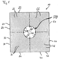
- the crossbar shown in Fig. 1 consists of four Wooden elements 20, 30, 40 and 50, the one of the beams in the longitudinal direction Enclose penetrating recess 70.
- Each of the Wooden elements 20, 30, 40 and 50 have two right angles delimiting surfaces 22, 24, 32, 34 including one another 42, 44, 52, 54 on which the annual rings 26, 36, 46 and 56 of the wooden elements run out approximately vertically.
- each of the wooden elements 20, 30, 40 and 50 also has one further boundary surface 28, 38, 48 and 58, which the Recess 70 passing through the bars.
- Each of the others Boundary surfaces 28, 38, 48 and 58 is in the form of a Longitudinal direction of the bar 10 extending segment of a cylindrical surface formed, each of the other boundary surfaces 28, 38, 48 and 58 in the circumferential direction extends about 90 ° of the circular cylinder surface.
- the recess 70 passing through the beam 10 is obtained an essentially in the form of a circular cylindrical surface formed wall.
- Crossbeams can be wooden elements with a planed lengthways further boundary surface in the form of the desired segments a circular cylindrical surface can be used.
- the crossbar shown in Fig. 1 can slight dislocations between the other boundary surfaces 28, 38, 48 and 58 along the planed wooden elements 20, 30, 40 and 50 are accepted as long as ensured is that the wall delimiting the recess 70 still is essentially circular cylindrical.
- the wooden component according to the invention shown in Fig. 2 be made by first connecting a connector 80 inserted into the recess 70 passing through the beam 10 and then poured with a potting compound 90.
- a stop element for example a knothole dowel is inserted into the recess 70.
- potting the connecting element 80 in the recess 70 passing through the beam 10 expediently one produced on the basis of polyurethanes Potting compound used.
- the connecting element of the wooden component shown in Fig. 2 for example in Form of a threaded rod provided with an external thread 82 80 be formed, in one after introduction to the Bar 10 penetrating recess 70 exposed end face of the connecting element 80 one with an internal thread 86 provided recess 84 is formed.
- the bar 10 penetrating recess 70 has a diameter of about 36.5 mm the outer diameter of the threaded rod 80 may be approximately 30 mm, so that an average width of the adhesive joint between the outer surface of the threaded rod 80 and the recess 70 delimiting wall of about 3.25 mm.
- the surface of the threaded rod 80 is preferably turned or rolled and corresponds expediently a metric ISO thread in which illustrated embodiment a metric ISO thread M30.
- the recess 84 can have a blind hole thread, M12, M16 or M20.
- the connecting element 80 expediently from a the shear strength of the Wood elements 20, 30, 40 and 50 exceeding shear strength steel.
- the blind hole thread 86 shown in FIG. 3 can be the threaded rod 80 also with a threaded pin or welded Be provided connecting parts.
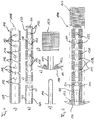
- the connecting element shown in FIGS. 4 and 5 consists essentially of a tubular part 110, a into which the tubular part 110 penetrates in the axial direction Cavity 116 insertable connector 120 and one inner part 130 which can also be inserted into cavity 116.
- the tubular part 110 forms the outer surface of the connecting element and can with a mechanical gearing the potting compound on the outer surface favoring surface structuring be provided.
- the outer surface of the tubular part 110 provided with an external thread 114.
- the production is for example from two embossed and punched half shells conceivable that are welded together if a wave-like Thread stamping on the outer surface is desired. At finished pipe products can be used on smooth surfaces become.
- connection component 120 serving other components has an internal thread 122 on.
- the connecting part 120 can be a cast part, which is then provided with a bore and the thread 122 will be executed, or as a turned part.
- the connecting part is expediently by welding or gluing connected to the tubular part 110. 4 and 5 shown embodiment of an inventive Connecting element is the connecting part 120 with a Through hole 124 provided the application of the potting compound enables.
- the inner part 130 shown in FIGS. 4 and 5 is in Form one made from recycled plastic, for example Plastic injection molded part.
- the outside diameter of the inner part 130 corresponds to the inner diameter of the tubular part 110 formed cavity 116.
- the inner part 130 can be installed in cavity 116 with a simple assembly adhesive be determined.
- the inner part 130 is in the form of a a bottom 134 closed on one of its end faces Tube with one extending in its axial direction Cavity 136 executed.
- the position of the elongated holes 112 corresponds to the tubular part 110.
- the inner part 130 serves for distributing the sealing compound and for fastening the sealing plug 160 (see below).
- the volume of the fastening of the connecting element required potting compound limited. That is special useful if there is a volume shrinkage when the casting compound hardens occurs when the one filled with the casting compound Pipe part that promotes the formation of voids.
- the inner part can be drilled out using an extended drill be used to manufacture a steel cable, for example of prestressed beams.
- the essentially from the tubular part 110, the Connecting part 120 and the inner part 130 existing connecting element 100 are also a cap 150, a Sealing plug 160 and a further sealing plug 140 assigned.
- the cap shown in Fig. 4e is made essentially from a plastic injection molded part that with a flexible sealing ring 152, for example made of foam or neoprene.
- the cap has 150 also has a nozzle 154, which is threaded or with one to make a detachable connection suitable clamping mechanism can be fixed in the connecting part 120 is.
- the cap 150 serves three functions. First can the connecting element with the help of mounting holes 156 of the cap penetrating screws in the beam hole be fixed. At the same time, by pressing the sealing ring sealed the adhesive joint so that no potting compound can leak. Third, the nozzle 154 protects the thread 122 in the connecting part 120 from contamination in the Application of the potting compound.
- the one, for example, from a piece of commercial Foam roller cord with circular cross-section existing Sealing plug 160 can be glued to the inner part 130 and together with this into the bar 10 passing through Recess 70 are pushed so as to pour out the potting compound to prevent inside the beam.
- the plug 140 also serves to prevent the Pouring out of the sealing compound. For this, the sealing plug 140 after the injection of the potting compound into the nozzle 154 Cap 150 pushed.
- Connecting element can ensure one uniform joint width over the entire length of the connecting element with the help of the elongated holes 112 and 132 used and used as a spacer arc springs guaranteed become. With such floor springs, the permeability the slots 112 and 132 for the potting compound hardly impaired.
- the potting compound can be injected into the adhesive joint under pressure and largely avoided the formation of voids in the joint become.
- the wooden building element is after application the casting compound and before it has completely hardened transportable and can be used, for example, to accelerate the Hardening reaction and to increase the strength properties the casting compound, for example by microwave radiation be heated.
- the cap can 150 and the plug 140 removed and reused become. This is generally only the sealing ring 152 to replace.
- connection elements for example also to the use of formed in the form of a structural steel Connection elements thought.
- that can Connecting element also in the recess passing through the beam be screwed in.
- the connecting element also in the form of further internal threads, for example formed connection areas for establishing a connection with one extending transversely to the longitudinal axis of the beam Component be arranged.
Landscapes
- Engineering & Computer Science (AREA)
- Architecture (AREA)
- Life Sciences & Earth Sciences (AREA)
- Wood Science & Technology (AREA)
- Civil Engineering (AREA)
- Structural Engineering (AREA)
- Rod-Shaped Construction Members (AREA)
Applications Claiming Priority (2)
| Application Number | Priority Date | Filing Date | Title |
|---|---|---|---|
| DE19748663 | 1997-11-04 | ||
| DE19748663 | 1997-11-04 |
Publications (2)
| Publication Number | Publication Date |
|---|---|
| EP0915213A2 true EP0915213A2 (fr) | 1999-05-12 |
| EP0915213A3 EP0915213A3 (fr) | 2000-10-18 |
Family
ID=7847563
Family Applications (1)
| Application Number | Title | Priority Date | Filing Date |
|---|---|---|---|
| EP98120660A Withdrawn EP0915213A3 (fr) | 1997-11-04 | 1998-11-04 | Elément de construction en bois et son procédé de fabrication |
Country Status (1)
| Country | Link |
|---|---|
| EP (1) | EP0915213A3 (fr) |
Cited By (3)
| Publication number | Priority date | Publication date | Assignee | Title |
|---|---|---|---|---|
| DE19940846A1 (de) * | 1999-08-27 | 2001-07-12 | Konstruktion Holz Werk Seubert | Bauelement |
| ES2352936A1 (es) * | 2010-06-28 | 2011-02-24 | Amatria Ingenieria, S.L, | Viga de madera armada. |
| DE102011110918B4 (de) | 2011-08-18 | 2018-12-27 | B & O Stammhaus GmbH & Co. KG | Gebäudeaufbau mit Wandaufbau für tragende Wände im mehrgeschossigen Gebäude und Verfahren zur Herstellung eines Gebäudeaufbaus |
Family Cites Families (12)
| Publication number | Priority date | Publication date | Assignee | Title |
|---|---|---|---|---|
| GB384998A (en) * | 1931-06-12 | 1932-12-12 | Francis Charles Morgan Giles | Improvements in or relating to the manufacture of wooden spars |
| GB561589A (en) * | 1942-11-20 | 1944-05-25 | William George Hitchins | Posts for buildings |
| FR2057564A5 (fr) * | 1969-08-28 | 1971-05-21 | Antignac Paul | |
| FR2512729A1 (fr) * | 1981-09-15 | 1983-03-18 | Chambon Alain | Systemes constructifs a base de poutres en bois massif reconstitue |
| EP0159452B1 (fr) * | 1984-04-16 | 1987-03-11 | Geilinger AG | Noeuds d'assemblage pour l'étais de bois de charpentes |
| CH673305A5 (en) * | 1986-05-02 | 1990-02-28 | Emil Roth & Co Ag | Filling bars for jointed frame trusses - with holding elements fixed by specified plastic adhesive |
| DE3638499C2 (de) * | 1986-11-11 | 1996-01-11 | Moser Karl Dipl Ing Fh | Holzverbinder |
| FR2621938B1 (fr) * | 1987-10-14 | 1990-01-26 | Grandclement Jean Claude | Pieces de bois allongees pour la construction et/ou la decoration de batiments |
| AU598684B2 (en) * | 1987-11-11 | 1990-06-28 | Robert David Eaton | Reinforced laminated timber |
| FR2673964B3 (fr) * | 1991-03-15 | 1993-07-09 | Michel Bretzner | Element d'ossature notamment pour construction bois. |
| EP0518246B1 (fr) * | 1991-06-14 | 1999-03-17 | Berthold Fries | Procédé de fabrication de poutre creuse en bois et les structures de cette poutre obtenues par ce procédé |
| US5660492A (en) * | 1993-12-18 | 1997-08-26 | Bathon; Leander | Coupling for wood structural members |
-
1998
- 1998-11-04 EP EP98120660A patent/EP0915213A3/fr not_active Withdrawn
Non-Patent Citations (1)
| Title |
|---|
| W. BECKER, D. BRAUN: "Die Kunststoffe, Kunststoff-Handbuch", 1990, HANSER VERLAG, MONCHEN |
Cited By (3)
| Publication number | Priority date | Publication date | Assignee | Title |
|---|---|---|---|---|
| DE19940846A1 (de) * | 1999-08-27 | 2001-07-12 | Konstruktion Holz Werk Seubert | Bauelement |
| ES2352936A1 (es) * | 2010-06-28 | 2011-02-24 | Amatria Ingenieria, S.L, | Viga de madera armada. |
| DE102011110918B4 (de) | 2011-08-18 | 2018-12-27 | B & O Stammhaus GmbH & Co. KG | Gebäudeaufbau mit Wandaufbau für tragende Wände im mehrgeschossigen Gebäude und Verfahren zur Herstellung eines Gebäudeaufbaus |
Also Published As
| Publication number | Publication date |
|---|---|
| EP0915213A3 (fr) | 2000-10-18 |
Similar Documents
| Publication | Publication Date | Title |
|---|---|---|
| DE69516864T2 (de) | Hochisolierende verbindungsstäbe und verfahren zu ihrer herstellung und ihrer anwendung in hochisolierten zusammengesetzten wänden | |
| EP0119318A1 (fr) | Assemblage invisible pour membres plans, en particulier pour meubles | |
| DE2224023A1 (de) | Verfahren zur Befestigung von Bolzen sowie Bolzenbefestigungsvorrichtung | |
| EP2299029A1 (fr) | Elément de coffrage doté d'une protection des angles et son procédé de fabrication | |
| DE3100730A1 (de) | Verfahren zum stuetzen und/oder verfestigen von hohlraumwaenden im tief-, berg- und tunnelbau, vorrichtung zum durchfuehren des verfahrens und in einem bohrloch der hohlraumwand sitzender verfestigungsanker | |
| DE102017002170A1 (de) | Abstandshalter und Befestiger für durch eine Fassade hindurch an Gebäuden zu befestigenden Teile | |
| DE9319497U1 (de) | Eine Verbindung von Holzwerkstoffen und Werkstoffen jeder Art mit Hilfe von Klebern | |
| EP1424453B1 (fr) | Manchon d'accouplement | |
| DE10139261C2 (de) | Wandelement sowie Verfahren zu dessen Herstellung | |
| EP0915213A2 (fr) | Elément de construction en bois et son procédé de fabrication | |
| DE2730633A1 (de) | Rahmen fuer fenster o.dgl. und verfahren zu seiner herstellung | |
| EP0686778B1 (fr) | Procédé pour fixer un élément de fixation dans un pièce en bois | |
| EP0724614B1 (fr) | Petit tube en verre contenant de la colle a deux composants, son procede de fabrication et son utilisation | |
| DE3836194A1 (de) | Verbinder fuer stabfoermige bewehrungsstaehle | |
| EP0996797A1 (fr) | Element de construction | |
| EP0697530B1 (fr) | Boulon d'ancrage pour béton ou similaire | |
| AT396160B (de) | Verfahren zur restaurierung eines hoelzernen konstruktionsteiles | |
| DE102009022828A1 (de) | Fachwerkträger einschließlich eines unterspannten Trägers sowie ein zugehöriges Verfahren zur Herstellung | |
| DE2915417A1 (de) | Verfahren zum verbinden von bau- oder konstruktionselementen und nach dem verfahren hergestellte bau- und konstruktionselemente | |
| DE102018001932A1 (de) | Abstandshalter und Befestiger für durch eine Fassade hindurch an Gebäuden zu befestigende Teile | |
| WO1993010362A1 (fr) | Boulon d'ancrage a coller | |
| EP0139176A1 (fr) | Procédé de fabrication de raccords pour tuyaux en matière plastique renforcée de fibres de verre et accessoires pour raccords | |
| DE2406770A1 (de) | Eckverbindung von kunststoff-hohlprofilen, insbesondere bei fluegel- oder blendrahmen fuer fenster und tueren | |
| EP2840194B1 (fr) | Élément en bois composite et procédé de fabrication | |
| DE7630026U1 (de) | Anschluss- und abdichtungseinrichtung zur ausbesserung von unerwuenschten hohlraeumen in vorzugsweise mauerwerk oder beton |
Legal Events
| Date | Code | Title | Description |
|---|---|---|---|
| PUAI | Public reference made under article 153(3) epc to a published international application that has entered the european phase |
Free format text: ORIGINAL CODE: 0009012 |
|
| AK | Designated contracting states |
Kind code of ref document: A2 Designated state(s): AT |
|
| AX | Request for extension of the european patent |
Free format text: AL;LT;LV;MK;RO;SI |
|
| K1C1 | Correction of patent application (title page) published |
Effective date: 19990512 |
|
| 19U | Interruption of proceedings before grant |
Effective date: 20000315 |
|
| 19W | Proceedings resumed before grant after interruption of proceedings |
Effective date: 20001129 |
|
| PUAL | Search report despatched |
Free format text: ORIGINAL CODE: 0009013 |
|
| AK | Designated contracting states |
Kind code of ref document: A3 Designated state(s): AT BE CH CY DE DK ES FI FR GB GR IE IT LI LU MC NL PT SE |
|
| AX | Request for extension of the european patent |
Free format text: AL;LT;LV;MK;RO;SI |
|
| RIC1 | Information provided on ipc code assigned before grant |
Free format text: 7E 04C 3/12 A, 7E 04C 3/14 B, 7E 04C 3/18 B, 7B 27M 3/00 B |
|
| AKX | Designation fees paid | ||
| REG | Reference to a national code |
Ref country code: DE Ref legal event code: 8566 |
|
| RBV | Designated contracting states (corrected) |
Designated state(s): AT |
|
| RAP1 | Party data changed (applicant data changed or rights of an application transferred) |
Owner name: SEUBERT, KLAUS, DIPL.-ING. (FH) |
|
| DBV | Designated contracting states (deleted) | ||
| STAA | Information on the status of an ep patent application or granted ep patent |
Free format text: STATUS: THE APPLICATION IS DEEMED TO BE WITHDRAWN |
|
| 18D | Application deemed to be withdrawn |
Effective date: 20020601 |