EP0915220B1 - Système de verrouillage mécanique et électronique - Google Patents
Système de verrouillage mécanique et électronique Download PDFInfo
- Publication number
- EP0915220B1 EP0915220B1 EP19980120076 EP98120076A EP0915220B1 EP 0915220 B1 EP0915220 B1 EP 0915220B1 EP 19980120076 EP19980120076 EP 19980120076 EP 98120076 A EP98120076 A EP 98120076A EP 0915220 B1 EP0915220 B1 EP 0915220B1
- Authority
- EP
- European Patent Office
- Prior art keywords
- pin
- locking system
- locking
- memory
- actuation
- Prior art date
- Legal status (The legal status is an assumption and is not a legal conclusion. Google has not performed a legal analysis and makes no representation as to the accuracy of the status listed.)
- Expired - Lifetime
Links
- 230000008878 coupling Effects 0.000 claims description 29
- 238000010168 coupling process Methods 0.000 claims description 29
- 238000005859 coupling reaction Methods 0.000 claims description 29
- 239000003990 capacitor Substances 0.000 claims description 7
- 210000000078 claw Anatomy 0.000 claims description 6
- 238000005516 engineering process Methods 0.000 claims description 3
- 230000007246 mechanism Effects 0.000 claims description 2
- 238000010200 validation analysis Methods 0.000 claims 3
- 230000008859 change Effects 0.000 description 24
- NMFHJNAPXOMSRX-PUPDPRJKSA-N [(1r)-3-(3,4-dimethoxyphenyl)-1-[3-(2-morpholin-4-ylethoxy)phenyl]propyl] (2s)-1-[(2s)-2-(3,4,5-trimethoxyphenyl)butanoyl]piperidine-2-carboxylate Chemical compound C([C@@H](OC(=O)[C@@H]1CCCCN1C(=O)[C@@H](CC)C=1C=C(OC)C(OC)=C(OC)C=1)C=1C=C(OCCN2CCOCC2)C=CC=1)CC1=CC=C(OC)C(OC)=C1 NMFHJNAPXOMSRX-PUPDPRJKSA-N 0.000 description 7
- 210000003746 feather Anatomy 0.000 description 4
- 238000004519 manufacturing process Methods 0.000 description 3
- 238000000034 method Methods 0.000 description 3
- 230000008569 process Effects 0.000 description 3
- 238000013475 authorization Methods 0.000 description 2
- 238000010276 construction Methods 0.000 description 2
- 238000013461 design Methods 0.000 description 2
- 238000011161 development Methods 0.000 description 2
- 230000018109 developmental process Effects 0.000 description 2
- 238000010586 diagram Methods 0.000 description 2
- 239000000463 material Substances 0.000 description 2
- 239000002184 metal Substances 0.000 description 2
- 229910000760 Hardened steel Inorganic materials 0.000 description 1
- 230000008901 benefit Effects 0.000 description 1
- 238000004364 calculation method Methods 0.000 description 1
- 238000006073 displacement reaction Methods 0.000 description 1
- 238000010292 electrical insulation Methods 0.000 description 1
- 239000002360 explosive Substances 0.000 description 1
- 238000009413 insulation Methods 0.000 description 1
- 238000002955 isolation Methods 0.000 description 1
- 230000004048 modification Effects 0.000 description 1
- 238000012986 modification Methods 0.000 description 1
- 239000007787 solid Substances 0.000 description 1
- 239000006228 supernatant Substances 0.000 description 1
- 238000012546 transfer Methods 0.000 description 1
- 239000006163 transport media Substances 0.000 description 1
Images


Classifications
-
- G—PHYSICS
- G07—CHECKING-DEVICES
- G07C—TIME OR ATTENDANCE REGISTERS; REGISTERING OR INDICATING THE WORKING OF MACHINES; GENERATING RANDOM NUMBERS; VOTING OR LOTTERY APPARATUS; ARRANGEMENTS, SYSTEMS OR APPARATUS FOR CHECKING NOT PROVIDED FOR ELSEWHERE
- G07C9/00—Individual registration on entry or exit
- G07C9/00174—Electronically operated locks; Circuits therefor; Nonmechanical keys therefor, e.g. passive or active electrical keys or other data carriers without mechanical keys
- G07C9/00817—Electronically operated locks; Circuits therefor; Nonmechanical keys therefor, e.g. passive or active electrical keys or other data carriers without mechanical keys where the code of the lock can be programmed
-
- E—FIXED CONSTRUCTIONS
- E05—LOCKS; KEYS; WINDOW OR DOOR FITTINGS; SAFES
- E05B—LOCKS; ACCESSORIES THEREFOR; HANDCUFFS
- E05B47/00—Operating or controlling locks or other fastening devices by electric or magnetic means
-
- E—FIXED CONSTRUCTIONS
- E05—LOCKS; KEYS; WINDOW OR DOOR FITTINGS; SAFES
- E05B—LOCKS; ACCESSORIES THEREFOR; HANDCUFFS
- E05B47/00—Operating or controlling locks or other fastening devices by electric or magnetic means
- E05B47/06—Controlling mechanically-operated bolts by electro-magnetically-operated detents
- E05B47/0676—Controlling mechanically-operated bolts by electro-magnetically-operated detents by disconnecting the handle
- E05B47/068—Controlling mechanically-operated bolts by electro-magnetically-operated detents by disconnecting the handle axially, i.e. with an axially disengaging coupling element
-
- E—FIXED CONSTRUCTIONS
- E05—LOCKS; KEYS; WINDOW OR DOOR FITTINGS; SAFES
- E05B—LOCKS; ACCESSORIES THEREFOR; HANDCUFFS
- E05B63/00—Locks or fastenings with special structural characteristics
- E05B63/0034—Locks for use instead of cylinder locks, e.g. locks with cylinder lock profile and a low security operating mechanism
-
- E—FIXED CONSTRUCTIONS
- E05—LOCKS; KEYS; WINDOW OR DOOR FITTINGS; SAFES
- E05B—LOCKS; ACCESSORIES THEREFOR; HANDCUFFS
- E05B47/00—Operating or controlling locks or other fastening devices by electric or magnetic means
- E05B47/0001—Operating or controlling locks or other fastening devices by electric or magnetic means with electric actuators; Constructional features thereof
- E05B47/0002—Operating or controlling locks or other fastening devices by electric or magnetic means with electric actuators; Constructional features thereof with electromagnets
- E05B47/0003—Operating or controlling locks or other fastening devices by electric or magnetic means with electric actuators; Constructional features thereof with electromagnets having a movable core
- E05B47/0004—Operating or controlling locks or other fastening devices by electric or magnetic means with electric actuators; Constructional features thereof with electromagnets having a movable core said core being linearly movable
-
- G—PHYSICS
- G07—CHECKING-DEVICES
- G07C—TIME OR ATTENDANCE REGISTERS; REGISTERING OR INDICATING THE WORKING OF MACHINES; GENERATING RANDOM NUMBERS; VOTING OR LOTTERY APPARATUS; ARRANGEMENTS, SYSTEMS OR APPARATUS FOR CHECKING NOT PROVIDED FOR ELSEWHERE
- G07C9/00—Individual registration on entry or exit
- G07C9/00174—Electronically operated locks; Circuits therefor; Nonmechanical keys therefor, e.g. passive or active electrical keys or other data carriers without mechanical keys
- G07C2009/00753—Electronically operated locks; Circuits therefor; Nonmechanical keys therefor, e.g. passive or active electrical keys or other data carriers without mechanical keys operated by active electrical keys
- G07C2009/00761—Electronically operated locks; Circuits therefor; Nonmechanical keys therefor, e.g. passive or active electrical keys or other data carriers without mechanical keys operated by active electrical keys with data transmission performed by connected means, e.g. mechanical contacts, plugs, connectors
Definitions
- the invention relates to an electronic-mechanical locking system according to the features indicated in the preamble of patent claim 1.
- the invention has the object, an electronic-mechanical locking system of the type mentioned in such a way that in addition to simple handling of the closing process and a high level of security and ease of change Authorization is realized.
- the locking device should have a compact and moreover break-proof construction. The entire locking device should find place in a door fitting and the operation should be possible only via an interface. In addition, the logging of the "key", including time and date, should be possible. After all, even in the event of a power failure, it should be possible to open at any time without losing the underlying security concept.
- the proposed electronic-mechanical locking system is characterized by a simple and functionally reliable construction and allows the specification and modification of the access authorization with little effort.
- a memory element is provided with a non-variable encoded record.
- This data set is expediently entered in the manufacturing process of the memory element in this, in particular by consecutive numbering of the serial number of the manufactured memory elements. It is for the respective memory element a record unique worldwide awarded, in particular as a serial number in the first memory element, which ensures almost 100% copy security.
- the first memory elements are used in particular ROM chips from Dallas. Moreover, it is of particular importance that the used reaching first memory elements or ROM chips are designed in two-wire technology, so only two wires or lines for making the electrical connection have with other components.
- the actuation of the locking device is effected by simply contacting with the authorized key or first memory element or ROM chip.
- a processor is provided with which the record of the first memory element is readable and comparable to the content of a memory.
- the data records of the authorized users are entered further elements.
- the read record with a registered in the memory is expediently electromechanically allows the opening of the lock.
- a second memory element is used, which in turn contains a non-changeable data record, in particular a unique serial number. This second memory element is designed in particular as a RAM chip from Dallas.
- the second memory element or the RAM chip contains, in addition to the unchangeable data record or its serial number, a freely writable and readable memory area which can be written and read via a suitable suitably matched PC software.
- This PC software allows the entry of a predetermined number of records of the first memory elements or keys, for example, up to 320 keys in the memory associated with the processor. Furthermore, an allocation of any number of keys to any number of locks or their processor memory is made by means of the program and managed.
- the second memory element described in this way is then contacted like a key with the processor authorized for it only, and the key data is transferred to the memory assigned to the processor.
- the second memory element is used according to the invention as a data transport medium and thus makes a change in the right to the castle on site very easy.
- a data exchange and in particular a change of the memory contents of the processor is not possible, so that unauthorized manipulations are excluded.
- a change of the memory contents and ultimately the access rights to the lock or door fitting on site readily by means of the legitimate second memory element easily be performed.
- a further memory is provided in the door fitting, which is mainly used for logging closing operations.
- the data content of a radio clock in particular a DCF 77 radio clock, is preferably also read out and stored together with the named data record in the further memory.
- the second memory element or RAM chip assigned to the respective processor is prepared for reading out, in particular by means of said PC program. The thus prepared second memory element is again contacted only with the fitting or the processor to evaluate the read data in the PC can.
- an emergency charger is also provided, which nevertheless allows the operation of the locking device and thus the opening of a door or the like in case of power failure.
- an auxiliary power source in particular in the form of a capacitor integrated in the door fitting. This auxiliary power source is charged via the same contact point provided for the first or second memory elements.
- a special charging electronics ensures that the rest arranged in the door fitting electronics, in particular the processor is disconnected.
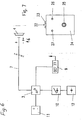
- Fig. 1 schematically shows the arranged on the fitting 1 closing device, which includes a processor 3 for reading a first memory element 4 and a second memory element 5 on a printed circuit board 2.
- the first memory element 4 is designed in particular as a ROM chip and the second memory element 5 as a RAM chip.
- the printed circuit board 2 further includes a further memory 8, a clock 9, which is preferably designed as a DCF 77 radio clock, as well as an emergency charging 10.
- the further, connected to the processor 3 memory 8 is for detecting closing messages, such as key data, time and Date, provided.
- the fitting 1 contains a battery 11.
- An auxiliary power source 12 preferably a capacitor, is provided for receiving the electrical energy for an emergency opening.
- a coupling element 14 which is in particular designed as a magnetic coupling.
- the coupling element 14 is associated with a change pin 15 which is connected on the one hand with a rotary knob 38 and the like and on the other hand via an actuating pin 40 with a closing element, in particular a locking lug 44. If by means of the processor the first memory element and thus an authorized key has been detected, the coupling element 14 is activated for a predetermined time of a few seconds to release an operation of the lock.
- the fitting has an outer shield 1, which is provided with individual chambers for receiving the processor 3, the capacitor 12 or the batteries 11.
- the arrangement of a contact pin 16 in conjunction with an insulating sleeve 17 and the attachment by the nut 21 is shown.
- the electrical coupling element 14 has the outer shield 1 towards a change pin 15 which engages in the knob 38, wherein the bearing takes place in an insert 39 and that in a trained there bearing 41, said insert is inserted into a bore of the outer shield 1.
- This insert 39 is provided to the knob 38 with a paragraph 48 as a pull protection and is based on a projection 50 of the outer shield 1 from.
- This projection 50 is covered by the rotary knob 38 by a material projection 42.
- an actuating pin 40 is arranged, which engages in a locking nose 44 with a square internal breakout.
- This locking lug 44 actuates a lock, such as a self-locking mortise lock 37, but all locks are used, which can be actuated via lock cylinder.
- a connecting web 45 which is supported by the provided in such mortise locks fastening screw 51, with the usually lock cylinder are mounted.
- bearing pin 52 On both sides of bearing pin 52 are provided on which bearing blocks 46 are mounted non-rotatably, between which in turn annular discs 53 are provided which support the nose 44.
- the system is covered inside with the help of an inner shield 38 and operable from the inside with the help of a pusher 43 with change pin 49.
- the outer shield 1 is covered inside with a cover 47. This design of the outer shield 1, the system can be pre-assembled, whereby the assembly is facilitated. After the actuating pin 40 performs a rotational movement it is expedient to accomplish the electrical connection 54 via slip rings.
- Both the outer shield 1 and the contact pin 16 are made of hardened steel.
- Fig. 4 shows an embodiment of the contacting
- the contact pin 16 is arranged by means of an insulating sleeve 17 in the fitting 1.
- the contact pin 16 is resiliently mounted by means of a spring 18 and connected to the data bus 7.
- the two mentioned memory elements are designed in two-wire technology and the ground or minus pole of the electronics is, as indicated by dashed lines 19, connected to the metal fitting 1.
- the contact pin 16 is arranged in isolation, to which the positive pole of the said memory elements is brought into contact when contacting and reading.
- Fig. 5 shows another embodiment of the contacting, whose contact pin 16 has a dome-shaped head on the outside of the fitting 11.
- On the inside of the fitting designed as a solid pin pin 16 is screwed to a nut 21 and by means of the insulating sleeve 17, the electrical insulation of the connected to the data bus 7 contact pin 16 with respect to the metallic fitting first
- Fig. 6 shows the block diagram of the locking device with the processor 3, the data bus 7 and the contact unit 6 for the first memory element 4 or ROM chip of the key.
- the emergency charging electronics 10, the battery 11 and also the clock 9 are electrically connected to the processor 3 in a supported manner.
- the capacitor 12 is associated with the emergency charging electronics 10 to provide sufficient energy for the electronics when needed.
- Fig. 7 schematically shows the emergency charger with Kontak busye 22, 23, which are electrically connected to the contact pin of the fitting or the fitting itself.
- the housing 24 includes a readout button 25, a battery indicator 26 and a charge indicator 27.
- the housing has the required charging electronics and battery installed.
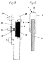
- Fig. 8 shows, partially in section, a key with a housing 28, which has the ground terminal of the second formed as a ROM chip memory element 5 and further comprises a contact element 29 for contacting with the door fitting 1. Further, the second memory element 5 is electrically connected via a contact spring 30 with a contact pin 31, which corresponds to the contact pin of the illustrated contacting and can be brought to this plant.
- the contact pin 31 of the key is electrically insulated with respect to the key housing 28 by means of an insulating sleeve 32 and an insulating washer 33.
- a contact element (not further illustrated here) is formed which is assigned to the second memory element or RAM chip.
- the connections to the explained PC software and the transfer of the key data entered into the RAM chip into the processor memory are effected via the contact element.
- Fig. 9 shows a further embodiment of the key with a handle 34, which may be made of plastic, and with the housing contained in a housing 35, preferably made of metal ROM chip 5.
- the housing 35 is connected to the negative terminal, while a central part thereof isolated is connected to the positive pole to allow the contacting of the illustrated contacting in a particularly simple manner.
- an actuating element in the illustration a knob 38, on an insert 39, which is inserted into the fitting 1.
- the knob 38 is held by means of a retaining ring 55 on the insert 39.
- an exchange pin 15 is inserted non-rotatably, which is displaceable in a correspondingly formed recess 70.
- an actuating pin 40 for the lock to be operated In the axial direction of the change pin 15 coaxially joins an actuating pin 40 for the lock to be operated.
- an electromagnet which is disposed within the bearing 41 of the insert 39.
- a bobbin 60 is inserted into a magnet housing 59, wherein the magnet housing 59 is supported with its stop ring 56 within the insert 39.
- On the pin member 67 of the exchange pin 15 is by means of a transversely inserted pin 61 ( Fig. 11 )
- An anchor 57 with its socket 66 is attached.
- the armature 57 is moved by energizing the magnet in the direction of arrow 71. In the initial position of the armature 57 is pressed by a spring 58 in the opposite direction.
- Of the electrical connection 54 of the electromagnet is led out within the bearing 41 in the insert 39 down.
- the change pin 15 is axially displaceable with its pin member 67 with the actuating pin 40 in its axial bore 69, but not secured against rotation, coupled by means of a clamping pin 62 which is disposed in a recess 68 in the axial bore 69 of the pin 40 ( Fig. 13 ). Assigned is a constriction 65 on the bolt part 67, wherein in the disengaged position as shown in FIG Fig. 10 the clamping pin 62 abuts the shoulder of the bolt part 67.
- the end of the socket part 66 of the armature 57 is formed as a claw 63, which can be pushed over a correspondingly formed end part as a latching element 64 of the actuating pin 40 ( Fig. 12 ), so that there is a positive connection.
- the pin member 67 is further inserted into the axial bore 69, wherein the clamping pin 62 is also displaced within the constriction 65.
- the engagement surface of the claw 63 and the corresponding engagement surfaces of the locking element 64 are shifted relative to the horizontal by an angle ⁇ , so that starting from the zero position with energized magnet of the change pin 15 after rotation by the angle ⁇ on the actuating pin 40 engages and thus the two parts are coupled.
- the locking system described is suitable for all electro-mechanical locks, such as safe locks, mortise locks, box locks, Multipoint Locks, Access Control Locks & Locks Like.
- Usable, ie locks that can be actuated via a mechanical shaft. This results in a secure engagement on the claw and it can be a greater torque transmitted. This in turn results in a lower power consumption and thus also a smaller capacitor for emergency power operation.
- FIG. 14 shows a box-additional lock, as for example in the DE 3816341 C2 is described.
- This lock can be advantageously combined with the electronic-mechanical locking system, wherein electrical components can be accommodated in the housing 85 of the lock, such as the circuit board 2 and the batteries 11.
- the box lock has a latch 84 which is provided with a rack 87, wherein in this rack 87, an actuating gear 88 engages, which meshes with a drive gear 86. To drive this drive gear 86, the actuating pin 40, which engages in a corresponding square recess of this gear 86 is used.
- FIG. 15 In the embodiment according to FIG. 15 is used to connect to a locking mechanism for actuating a lock for a lock latches an actuator or actuating pin 40 which is mechanically coupled to an actuating member 38 to which a knob or the like for operating this actuating member 38 is attached.
- the actuating element has a thickened cylindrical part 80, to which an alternating pin 15 connects, wherein at a distance from the cylindrical part 80, a polygonal section, for example, a square section 76 connects. In the front part of the change pin 15 this is provided with a constriction 77.
- the actuating part 38 has a cylindrical shaft 72, to which, towards the actuating element 40, a disk-shaped enlarged receiving part 73 connects.
- the shaft 72 is provided with a blind hole 79 into which the change pin 15 is inserted.
- the receiving part 73 has an approximately oval-shaped, axially extending recess 81.
- a disc-shaped coupling member 74 which is displaceable on the change pin 15 and in the middle has a Mehrkantausnaturalung 78.
- the height of this coupling part 74 is less than the height of the recess 81, so that this part 74 has a displacement within the recess 81.
- the Mehrkantausnaturalung 78 corresponds to the polygonal section 76 of the change pin 15.
- To move the coupling part 74 is an electromagnet 60 whose coil is arranged with electrical connection 54 in a magnet housing or a coil holder 59.
- the coil holder 59 is attached to the fitting or an insert of the fitting. It sits in the region of a portion 82 of the change pin 15.
- a spring 75 Between the coil 60 and the coupling member 74 is a spring 75. Furthermore, the actuating member 38 and the actuator 40 are axially by a locking pin 83rd held in the operating part 38 and a constriction 77 on the front part of the change pin 15.
- This embodiment has the particular advantage that the risk of damage to the electrical connection to the coupling element avoided and the design complexity is simplified.
Landscapes
- Engineering & Computer Science (AREA)
- Structural Engineering (AREA)
- Physics & Mathematics (AREA)
- General Physics & Mathematics (AREA)
- Lock And Its Accessories (AREA)
Claims (22)
- Système de fermeture électronique et mécanique pour cylindre de fermeture sans mécanisme de fermeture pour l'actionnement d'un taquet de fermeture (44) pour des serrures comprenant un système de verrouillage propre, contenant une serrure (37), une clé avec un premier élément de mémoire (4) et une électronique (2), au moyen de laquelle un élément d'accouplement (14) peut être actionné, afin de permettre un actionnement de la serrure (37) si l'on utilise une clé reconnue autorisée, caractérisé en ce que, pour programmer la serrure (37) en ce qui concerne l'autorisation de clé, il est prévu un second élément de mémoire (5) autorisé dans lequel les données des clés à autoriser peuvent être entrées et qui contient un ensemble de données non modifiables, en ce que l'électronique (2) contient un processeur (3) et une mémoire (8) attribuée, dans laquelle les ensembles de données de clés à autoriser peuvent être entrés au moyen du second élément de mémoire (5) autorisé, en ce que l'autorisation du second élément de mémoire (5) concernant le processeur (3) est effectuée par l'entrée du second ensemble de données non modifiables du second élément de mémoire (5) dans le processeur (3), et en ce que, pour la programmation, les ensembles de données non modifiables des clés à autoriser peuvent être entrés dans le second élément de mémoire (5) et peuvent être transmis au moyen de cette clé dans ladite mémoire (8) de l'électronique (2).
- Système de fermeture électronique et mécanique selon la revendication 1, caractérisé en ce qu'il est prévu comme cylindre de fermeture un taquet de fermeture (44) logé sur la serrure (37) conçue comme serrure à mortaiser (37), taquet dans lequel une goupille d'actionnement (40) s'engage par complémentarité de formes, laquelle peut être couplée par le biais de l'élément d'accouplement (14) avec un bouton rotatif (38) disposé à l'extérieur sur une armature (1).
- Système de fermeture selon la revendication 2, caractérisé en ce qu'une barrette de liaison (45) avec boulon de support (52) est fixée sur la serrure à mortaiser (37) au moyen d'une vis de fixation pour cylindre de fermeture (51), boulon sur lequel sont disposés des supports de palier (46), sur lesquels le taquet de fermeture (44) est logé.
- Système de fermeture selon les revendications 2 et 3, caractérisé en ce que l'armature (1) respectivement la plaque extérieure présente des chambres pour le processeur (3), un condensateur (12), des batteries (11) et similaires.
- Système de fermeture selon l'une quelconque des revendications 2 à 4, caractérisé en ce que l'élément d'accouplement (14) est monté sur une plaque extérieure (1).
- Système de fermeture selon la revendication 2, caractérisé en ce que l'élément d'accouplement est disposé entre un élément d'actionnement (38) avec goupille interchangeable (15) et une goupille d'actionnement (40) et présente un système d'ancrage (57) relié à la goupille interchangeable (15), la goupille interchangeable (15) étant disposée sur l'élément d'actionnement (38) de façon bloquée en rotation et coulissante, et en ce que la goupille interchangeable (15) peut être couplée par déplacement du système d'ancrage (57) au moyen d'un électroaimant (59, 60) avec la goupille d'actionnement (40).
- Système de fermeture selon la revendication 6, caractérisé en ce que l'électroaimant (59, 60) présentant un boîtier d'aimant (59) et un corps de bobine (60) est disposé dans une pièce d'insertion (39) de l'armature (1), le système d'ancrage (57) étant soutenu au moyen d'un ressort (58) sur l'électroaimant (59, 60).
- Système de fermeture selon les revendications 6 et 7, caractérisé en ce que l'extrémité de la partie de douille (66) du système d'ancrage (57) présente une griffe (63) qui recouvre un élément d'encliquetage (64) adopté de la goupille d'actionnement (40).
- Système de fermeture selon les revendications 6 à 8, caractérisé en ce que la goupille interchangeable (15) et la goupille d'actionnement (40) sont reliées l'une à l'autre au moyen d'une goupille de serrage (62) disposée transversalement dans un rétrécissement (65) de la goupille interchangeable (15).
- Système de fermeture selon la revendication 8 ou 9, caractérisé en ce que la griffe (63) et l'élément d'encliquetage (64) présentent dans la position d'encliquetage un angle de torsion par rapport à l'horizontale.
- Système de fermeture selon la revendication 2, caractérisé en ce que l'élément d'accouplement (14) est disposé entre un élément d'actionnement avec goupille interchangeable (15) et une partie d'actionnement (38) et l'élément d'actionnement (40) présente une partie polygonale (76) dans la zone de la goupille interchangeable (15), en ce que la goupille interchangeable (15) est disposée de façon rotative dans la partie d'actionnement (38), bloquée axialement, en ce que derrière la partie polygonale (76) est prévu un électroaimant (60) qui agit sur une partie d'accouplement (74) en forme de disque, coulissant sur la goupille interchangeable (15), la partie d'accouplement (74) présentant un évidement (78) adapté à la forme de la partie polygonale (76), et la partie d'accouplement (74) pouvant coulisser axialement dans une partie de logement (73) de forme appropriée.
- Système de fermeture selon la revendication 11, caractérisé en ce que l'électroaimant (60) est disposé dans un boîtier de bobine (59).
- Système de fermeture selon la revendication 11 ou 12, caractérisé en ce que la partie d'accouplement (74) est soutenue sur un ressort (75) contre l'électroaimant (60).
- Système de fermeture selon les revendications 11 à 13, caractérisé en ce que la goupille interchangeable (15) est maintenue dans un trou borgne (79) axial de la goupille d'actionnement (38) au moyen d'une goupille de blocage (83) agencée transversalement, s'engageant dans un rétrécissement (77) de la goupille interchangeable (15).
- Système de fermeture selon la revendication 1, caractérisé en ce que le premier élément de mémoire (4) est conçu sous forme de puce ROM et le second élément mémoire (5) sous forme de puce RAM et en ce que les éléments de mémoire (4, 5) contiennent des ensembles de données non modifiables, en particulier des numéros de série continus et uniques.
- Système de fermeture selon l'une quelconque des revendications 1 à 15, caractérisé en ce que l'électronique et/ou les éléments de mémoire (4, 5) ainsi que le processeur (3) sont conçus dans la technologie à deux fils.
- Système de fermeture selon les revendications 1 à 16, caractérisé en ce que l'autorisation du second élément de mémoire (5) concernant le processeur (3) est effectuée par l'entrée de l'ensemble de données non modifiables dans le code source du processeur (3).
- Système de fermeture selon l'une quelconque des revendications 1 à 17, caractérisé en ce que la mémoire (3) dans laquelle les ensembles de données de clés à autoriser peuvent être entrés au moyen du second élément de mémoire (5) autorisé, est intégrée dans le processeur (3).
- Système de fermeture selon l'une quelconque des revendications 1 à 18, caractérisé en ce qu'il est disposé dans une armature (1), et présente une unité d'établissement de contact (6) pour le premier élément de mémoire (4) d'une clé ou le second élément de mémoire (5) pour l'entrée ou la modification de la clé à autoriser, la liaison électrique au moins avec le processeur pouvant être effectuée au moyen d'une ligne (7) ou d'un bus de données.
- Système de fermeture selon l'une quelconque des revendications 1 à 19, caractérisé en ce qu'une autre mémoire (8) est prévue pour des messages de fermeture, qui contiennent en particulier l'ensemble de données d'une clé utilisée, l'heure et la date.
- Système de fermeture selon la revendication 20, caractérisé en ce qu'une pendule (9), qui est prévue en particulier sous forme d'horloge télépilotée DCF 77, est prévue pour l'enregistrement de l'heure et de la date.
- Système de fermeture selon l'une quelconque des revendications 1 à 21, caractérisé en ce qu'un dispositif de chargement de secours est prévu avec une source de courant auxiliaire (12), de préférence un condensateur, et/ou en ce que le dispositif de chargement de secours peut être chargé par une ligne (7) et une unité d'établissement de contact (6) au moyen d'un appareil de chargement de secours.
Applications Claiming Priority (6)
| Application Number | Priority Date | Filing Date | Title |
|---|---|---|---|
| DE1997149081 DE19749081C2 (de) | 1997-11-06 | 1997-11-06 | Elektronisch-mechanisches Schließsystem |
| DE19749081 | 1997-11-06 | ||
| DE19801087 | 1998-01-14 | ||
| DE1998101087 DE19801087A1 (de) | 1997-11-06 | 1998-01-14 | Elektronisch-mechanisches Schließsystem |
| DE19829958A DE19829958B4 (de) | 1997-11-06 | 1998-07-04 | Elektronisch-mechanisches Schließsystem |
| DE19829958 | 1998-07-04 |
Publications (3)
| Publication Number | Publication Date |
|---|---|
| EP0915220A2 EP0915220A2 (fr) | 1999-05-12 |
| EP0915220A3 EP0915220A3 (fr) | 2002-01-09 |
| EP0915220B1 true EP0915220B1 (fr) | 2008-09-24 |
Family
ID=27217898
Family Applications (1)
| Application Number | Title | Priority Date | Filing Date |
|---|---|---|---|
| EP19980120076 Expired - Lifetime EP0915220B1 (fr) | 1997-11-06 | 1998-10-23 | Système de verrouillage mécanique et électronique |
Country Status (1)
| Country | Link |
|---|---|
| EP (1) | EP0915220B1 (fr) |
Families Citing this family (4)
| Publication number | Priority date | Publication date | Assignee | Title |
|---|---|---|---|---|
| DE19939892A1 (de) * | 1999-08-23 | 2001-03-01 | Wilke Heinrich Hewi Gmbh | Adapterelement für Türen |
| DK200500222U3 (da) * | 2005-09-30 | 2005-12-23 | Birkegaarden Holding As | Biometrisk lås kombineret med kodetastatur + mekanisk lås til 3-punkt dör |
| AT10705U1 (de) * | 2007-11-05 | 2009-08-15 | Sitech Sicherheitstechnik Gmbh | Schild für ein schloss |
| AT516346A1 (de) | 2014-09-15 | 2016-04-15 | Makivic Michael | Türschild für einen Türbeschlag |
Family Cites Families (12)
| Publication number | Priority date | Publication date | Assignee | Title |
|---|---|---|---|---|
| US4534194A (en) * | 1981-03-16 | 1985-08-13 | Kadex, Incorporated | Electronic lock system |
| DE3421540A1 (de) * | 1984-06-08 | 1986-01-02 | Audi AG, 8070 Ingolstadt | Schliesssystem mit einem batteriebetriebenen infrarot-handsender |
| DE3543527A1 (de) * | 1985-12-10 | 1987-06-11 | Karl Bergweiler | Langschild-garnitur, mit der jedes tuerschloss elektronisch steuerbar zu machen ist |
| DE3602989A1 (de) * | 1986-01-31 | 1987-11-19 | Herz Gmbh | Elektromechanisches schlosssystem |
| FR2607611B1 (fr) * | 1986-11-28 | 1989-02-03 | Neiman Sa | Telecommande codee a changement |
| US4856310A (en) * | 1987-04-29 | 1989-08-15 | Raoul Parienti | Electronic lock |
| DE3805453A1 (de) * | 1988-02-22 | 1989-08-31 | Bks Gmbh | Elektronisch-mechanisch arbeitende tuerverschlussanlage |
| DE3816341A1 (de) | 1988-05-13 | 1989-11-23 | Sicherheit Und Service Inh Kla | Kombinationsschloss |
| US5040391A (en) * | 1990-08-07 | 1991-08-20 | Taiwan Fu Hsing Industry Co., Ltd. | Structure for controlling the dead bolt used in an electronic lock |
| GB2284852B (en) * | 1991-09-19 | 1996-02-07 | Klidi Technology Corp | Remotely-operated self-contained electronic lock security system assembly |
| US5447047A (en) * | 1992-09-23 | 1995-09-05 | Taiwan Fu Hsing Industrial Co., Ltd. | Dead bolt of a door lock |
| GB2305965A (en) * | 1995-10-07 | 1997-04-23 | Taylor Lock | Electrically-operated spindle |
-
1998
- 1998-10-23 EP EP19980120076 patent/EP0915220B1/fr not_active Expired - Lifetime
Also Published As
| Publication number | Publication date |
|---|---|
| EP0915220A2 (fr) | 1999-05-12 |
| EP0915220A3 (fr) | 2002-01-09 |
Similar Documents
| Publication | Publication Date | Title |
|---|---|---|
| EP1214491B1 (fr) | Unite de verrouillage pour une serrure a barillet | |
| DE19851308C2 (de) | Schließzylinder | |
| DE69304904T2 (de) | Zylinderschloss | |
| WO2004057137A1 (fr) | Dispositif de verrouillage | |
| DE19930054C2 (de) | Elektromechanisches Schließsystem | |
| DE60115075T2 (de) | Elektromechanisches zylinderschloss und schlüssel | |
| DE3602989A1 (de) | Elektromechanisches schlosssystem | |
| EP0819810B1 (fr) | Ferrure pour une serrure | |
| EP1079051B1 (fr) | Dispositif de verrouillage | |
| DE69002786T2 (de) | Schloss mit einem elektronischen Schlüssel. | |
| EP0298193B1 (fr) | Cylindre de serrure à goupille électromagnétique | |
| CH668616A5 (de) | Schliesseinrichtung fuer ein mechanisch/elektronisches schliess-system. | |
| DE19829927C2 (de) | Elektronischer Türbeschlag | |
| EP0224607A1 (fr) | Dispositif de fermeture comportant un système électronique d'identification | |
| EP1256671B1 (fr) | Rosette pour serrure cylindrique | |
| EP0542944B1 (fr) | Serrure a ame de cylindre motorisee | |
| DE3515888A1 (de) | Mechanisch-elektronische schliesseinrichtung | |
| EP0805905B1 (fr) | Mécanisme de fermeture de porte | |
| EP0915220B1 (fr) | Système de verrouillage mécanique et électronique | |
| EP0094592A1 (fr) | Dispositif de fermeture | |
| DE3707201A1 (de) | Doppelschliesszylinder | |
| DE19749081C2 (de) | Elektronisch-mechanisches Schließsystem | |
| DE4314903A1 (de) | Schloßanordnung | |
| AT525744B1 (de) | Schließeinrichtung | |
| EP3412851B1 (fr) | Dispositif de fouillot de loquet pour une serrure |
Legal Events
| Date | Code | Title | Description |
|---|---|---|---|
| PUAI | Public reference made under article 153(3) epc to a published international application that has entered the european phase |
Free format text: ORIGINAL CODE: 0009012 |
|
| AK | Designated contracting states |
Kind code of ref document: A2 Designated state(s): AT BE CH CY DE DK ES FI FR GB GR IE IT LI LU MC NL PT SE Kind code of ref document: A2 Designated state(s): AT CH DE DK ES FR GB IE IT LI NL SE |
|
| AX | Request for extension of the european patent |
Free format text: AL;LT;LV;MK;RO;SI |
|
| RAP1 | Party data changed (applicant data changed or rights of an application transferred) |
Owner name: DRUMM GMBH |
|
| RIN1 | Information on inventor provided before grant (corrected) |
Inventor name: DRUMM GMBH |
|
| RIN1 | Information on inventor provided before grant (corrected) |
Inventor name: DRUMM, KLAUS PETER |
|
| PUAL | Search report despatched |
Free format text: ORIGINAL CODE: 0009013 |
|
| AK | Designated contracting states |
Kind code of ref document: A3 Designated state(s): AT BE CH CY DE DK ES FI FR GB GR IE IT LI LU MC NL PT SE |
|
| AX | Request for extension of the european patent |
Free format text: AL;LT;LV;MK;RO;SI |
|
| 17P | Request for examination filed |
Effective date: 20020326 |
|
| AKX | Designation fees paid |
Free format text: AT CH DE DK ES FR GB IE IT LI NL SE |
|
| 17Q | First examination report despatched |
Effective date: 20040429 |
|
| GRAP | Despatch of communication of intention to grant a patent |
Free format text: ORIGINAL CODE: EPIDOSNIGR1 |
|
| GRAS | Grant fee paid |
Free format text: ORIGINAL CODE: EPIDOSNIGR3 |
|
| GRAA | (expected) grant |
Free format text: ORIGINAL CODE: 0009210 |
|
| AK | Designated contracting states |
Kind code of ref document: B1 Designated state(s): AT CH DE DK ES FR GB IE IT LI NL SE |
|
| REG | Reference to a national code |
Ref country code: GB Ref legal event code: FG4D Free format text: NOT ENGLISH |
|
| REG | Reference to a national code |
Ref country code: CH Ref legal event code: EP |
|
| REG | Reference to a national code |
Ref country code: IE Ref legal event code: FG4D Free format text: LANGUAGE OF EP DOCUMENT: GERMAN |
|
| REF | Corresponds to: |
Ref document number: 59814292 Country of ref document: DE Date of ref document: 20081106 Kind code of ref document: P |
|
| REG | Reference to a national code |
Ref country code: CH Ref legal event code: NV Representative=s name: SCHMAUDER & PARTNER AG PATENTANWALTSBUERO |
|
| REG | Reference to a national code |
Ref country code: IE Ref legal event code: FD4D |
|
| PG25 | Lapsed in a contracting state [announced via postgrant information from national office to epo] |
Ref country code: ES Free format text: LAPSE BECAUSE OF FAILURE TO SUBMIT A TRANSLATION OF THE DESCRIPTION OR TO PAY THE FEE WITHIN THE PRESCRIBED TIME-LIMIT Effective date: 20090104 |
|
| PG25 | Lapsed in a contracting state [announced via postgrant information from national office to epo] |
Ref country code: IE Free format text: LAPSE BECAUSE OF FAILURE TO SUBMIT A TRANSLATION OF THE DESCRIPTION OR TO PAY THE FEE WITHIN THE PRESCRIBED TIME-LIMIT Effective date: 20080924 Ref country code: DK Free format text: LAPSE BECAUSE OF FAILURE TO SUBMIT A TRANSLATION OF THE DESCRIPTION OR TO PAY THE FEE WITHIN THE PRESCRIBED TIME-LIMIT Effective date: 20080924 |
|
| PLBE | No opposition filed within time limit |
Free format text: ORIGINAL CODE: 0009261 |
|
| REG | Reference to a national code |
Ref country code: CH Ref legal event code: PCAR Free format text: SCHMAUDER & PARTNER AG PATENT- UND MARKENANWAELTE VSP;ZWAENGIWEG 7;8038 ZUERICH (CH) |
|
| STAA | Information on the status of an ep patent application or granted ep patent |
Free format text: STATUS: NO OPPOSITION FILED WITHIN TIME LIMIT |
|
| GBPC | Gb: european patent ceased through non-payment of renewal fee |
Effective date: 20081224 |
|
| PG25 | Lapsed in a contracting state [announced via postgrant information from national office to epo] |
Ref country code: IT Free format text: LAPSE BECAUSE OF FAILURE TO SUBMIT A TRANSLATION OF THE DESCRIPTION OR TO PAY THE FEE WITHIN THE PRESCRIBED TIME-LIMIT Effective date: 20080924 |
|
| 26N | No opposition filed |
Effective date: 20090625 |
|
| PG25 | Lapsed in a contracting state [announced via postgrant information from national office to epo] |
Ref country code: GB Free format text: LAPSE BECAUSE OF NON-PAYMENT OF DUE FEES Effective date: 20081224 |
|
| PG25 | Lapsed in a contracting state [announced via postgrant information from national office to epo] |
Ref country code: SE Free format text: LAPSE BECAUSE OF FAILURE TO SUBMIT A TRANSLATION OF THE DESCRIPTION OR TO PAY THE FEE WITHIN THE PRESCRIBED TIME-LIMIT Effective date: 20081224 |
|
| PGFP | Annual fee paid to national office [announced via postgrant information from national office to epo] |
Ref country code: CH Payment date: 20100225 Year of fee payment: 12 |
|
| PGFP | Annual fee paid to national office [announced via postgrant information from national office to epo] |
Ref country code: FR Payment date: 20100310 Year of fee payment: 12 |
|
| PGFP | Annual fee paid to national office [announced via postgrant information from national office to epo] |
Ref country code: DE Payment date: 20091218 Year of fee payment: 12 Ref country code: AT Payment date: 20100224 Year of fee payment: 12 |
|
| PGFP | Annual fee paid to national office [announced via postgrant information from national office to epo] |
Ref country code: NL Payment date: 20100225 Year of fee payment: 12 |
|
| REG | Reference to a national code |
Ref country code: NL Ref legal event code: V1 Effective date: 20110501 |
|
| REG | Reference to a national code |
Ref country code: CH Ref legal event code: PL |
|
| PG25 | Lapsed in a contracting state [announced via postgrant information from national office to epo] |
Ref country code: CH Free format text: LAPSE BECAUSE OF NON-PAYMENT OF DUE FEES Effective date: 20101031 Ref country code: FR Free format text: LAPSE BECAUSE OF NON-PAYMENT OF DUE FEES Effective date: 20101102 Ref country code: LI Free format text: LAPSE BECAUSE OF NON-PAYMENT OF DUE FEES Effective date: 20101031 |
|
| REG | Reference to a national code |
Ref country code: FR Ref legal event code: ST Effective date: 20110630 |
|
| PG25 | Lapsed in a contracting state [announced via postgrant information from national office to epo] |
Ref country code: NL Free format text: LAPSE BECAUSE OF NON-PAYMENT OF DUE FEES Effective date: 20110501 Ref country code: AT Free format text: LAPSE BECAUSE OF NON-PAYMENT OF DUE FEES Effective date: 20101023 |
|
| REG | Reference to a national code |
Ref country code: DE Ref legal event code: R119 Ref document number: 59814292 Country of ref document: DE Effective date: 20110502 |
|
| PG25 | Lapsed in a contracting state [announced via postgrant information from national office to epo] |
Ref country code: DE Free format text: LAPSE BECAUSE OF NON-PAYMENT OF DUE FEES Effective date: 20110502 |