EP0915247A1 - Systeme d'alimentation pour moteur a combustion interne - Google Patents
Systeme d'alimentation pour moteur a combustion interne Download PDFInfo
- Publication number
- EP0915247A1 EP0915247A1 EP96937600A EP96937600A EP0915247A1 EP 0915247 A1 EP0915247 A1 EP 0915247A1 EP 96937600 A EP96937600 A EP 96937600A EP 96937600 A EP96937600 A EP 96937600A EP 0915247 A1 EP0915247 A1 EP 0915247A1
- Authority
- EP
- European Patent Office
- Prior art keywords
- fuel
- gas
- engine
- internal combustion
- pressure reducer
- Prior art date
- Legal status (The legal status is an assumption and is not a legal conclusion. Google has not performed a legal analysis and makes no representation as to the accuracy of the status listed.)
- Withdrawn
Links
Images

Classifications
-
- F—MECHANICAL ENGINEERING; LIGHTING; HEATING; WEAPONS; BLASTING
- F02—COMBUSTION ENGINES; HOT-GAS OR COMBUSTION-PRODUCT ENGINE PLANTS
- F02M—SUPPLYING COMBUSTION ENGINES IN GENERAL WITH COMBUSTIBLE MIXTURES OR CONSTITUENTS THEREOF
- F02M13/00—Arrangements of two or more separate carburettors; Carburettors using more than one fuel
- F02M13/08—Carburettors adapted to use liquid and gaseous fuels, e.g. alternatively
-
- F—MECHANICAL ENGINEERING; LIGHTING; HEATING; WEAPONS; BLASTING
- F02—COMBUSTION ENGINES; HOT-GAS OR COMBUSTION-PRODUCT ENGINE PLANTS
- F02B—INTERNAL-COMBUSTION PISTON ENGINES; COMBUSTION ENGINES IN GENERAL
- F02B43/00—Engines characterised by operating on gaseous fuels; Plants including such engines
-
- F—MECHANICAL ENGINEERING; LIGHTING; HEATING; WEAPONS; BLASTING
- F02—COMBUSTION ENGINES; HOT-GAS OR COMBUSTION-PRODUCT ENGINE PLANTS
- F02B—INTERNAL-COMBUSTION PISTON ENGINES; COMBUSTION ENGINES IN GENERAL
- F02B69/00—Internal-combustion engines convertible into other combustion-engine type, not provided for in F02B11/00; Internal-combustion engines of different types characterised by constructions facilitating use of same main engine-parts in different types
- F02B69/02—Internal-combustion engines convertible into other combustion-engine type, not provided for in F02B11/00; Internal-combustion engines of different types characterised by constructions facilitating use of same main engine-parts in different types for different fuel types, other than engines indifferent to fuel consumed, e.g. convertible from light to heavy fuel
-
- F—MECHANICAL ENGINEERING; LIGHTING; HEATING; WEAPONS; BLASTING
- F02—COMBUSTION ENGINES; HOT-GAS OR COMBUSTION-PRODUCT ENGINE PLANTS
- F02D—CONTROLLING COMBUSTION ENGINES
- F02D19/00—Controlling engines characterised by their use of non-liquid fuels, pluralities of fuels, or non-fuel substances added to the combustible mixtures
- F02D19/02—Controlling engines characterised by their use of non-liquid fuels, pluralities of fuels, or non-fuel substances added to the combustible mixtures peculiar to engines working with gaseous fuels
- F02D19/021—Control of components of the fuel supply system
- F02D19/023—Control of components of the fuel supply system to adjust the fuel mass or volume flow
-
- F—MECHANICAL ENGINEERING; LIGHTING; HEATING; WEAPONS; BLASTING
- F02—COMBUSTION ENGINES; HOT-GAS OR COMBUSTION-PRODUCT ENGINE PLANTS
- F02D—CONTROLLING COMBUSTION ENGINES
- F02D19/00—Controlling engines characterised by their use of non-liquid fuels, pluralities of fuels, or non-fuel substances added to the combustible mixtures
- F02D19/06—Controlling engines characterised by their use of non-liquid fuels, pluralities of fuels, or non-fuel substances added to the combustible mixtures peculiar to engines working with pluralities of fuels, e.g. alternatively with light and heavy fuel oil, other than engines indifferent to the fuel consumed
- F02D19/0639—Controlling engines characterised by their use of non-liquid fuels, pluralities of fuels, or non-fuel substances added to the combustible mixtures peculiar to engines working with pluralities of fuels, e.g. alternatively with light and heavy fuel oil, other than engines indifferent to the fuel consumed characterised by the type of fuels
- F02D19/0642—Controlling engines characterised by their use of non-liquid fuels, pluralities of fuels, or non-fuel substances added to the combustible mixtures peculiar to engines working with pluralities of fuels, e.g. alternatively with light and heavy fuel oil, other than engines indifferent to the fuel consumed characterised by the type of fuels at least one fuel being gaseous, the other fuels being gaseous or liquid at standard conditions
- F02D19/0647—Controlling engines characterised by their use of non-liquid fuels, pluralities of fuels, or non-fuel substances added to the combustible mixtures peculiar to engines working with pluralities of fuels, e.g. alternatively with light and heavy fuel oil, other than engines indifferent to the fuel consumed characterised by the type of fuels at least one fuel being gaseous, the other fuels being gaseous or liquid at standard conditions the gaseous fuel being liquefied petroleum gas [LPG], liquefied natural gas [LNG], compressed natural gas [CNG] or dimethyl ether [DME]
-
- F—MECHANICAL ENGINEERING; LIGHTING; HEATING; WEAPONS; BLASTING
- F02—COMBUSTION ENGINES; HOT-GAS OR COMBUSTION-PRODUCT ENGINE PLANTS
- F02D—CONTROLLING COMBUSTION ENGINES
- F02D19/00—Controlling engines characterised by their use of non-liquid fuels, pluralities of fuels, or non-fuel substances added to the combustible mixtures
- F02D19/06—Controlling engines characterised by their use of non-liquid fuels, pluralities of fuels, or non-fuel substances added to the combustible mixtures peculiar to engines working with pluralities of fuels, e.g. alternatively with light and heavy fuel oil, other than engines indifferent to the fuel consumed
- F02D19/08—Controlling engines characterised by their use of non-liquid fuels, pluralities of fuels, or non-fuel substances added to the combustible mixtures peculiar to engines working with pluralities of fuels, e.g. alternatively with light and heavy fuel oil, other than engines indifferent to the fuel consumed simultaneously using pluralities of fuels
- F02D19/081—Adjusting the fuel composition or mixing ratio; Transitioning from one fuel to the other
-
- F—MECHANICAL ENGINEERING; LIGHTING; HEATING; WEAPONS; BLASTING
- F02—COMBUSTION ENGINES; HOT-GAS OR COMBUSTION-PRODUCT ENGINE PLANTS
- F02M—SUPPLYING COMBUSTION ENGINES IN GENERAL WITH COMBUSTIBLE MIXTURES OR CONSTITUENTS THEREOF
- F02M21/00—Apparatus for supplying engines with non-liquid fuels, e.g. gaseous fuels stored in liquid form
- F02M21/02—Apparatus for supplying engines with non-liquid fuels, e.g. gaseous fuels stored in liquid form for gaseous fuels
- F02M21/0218—Details on the gaseous fuel supply system, e.g. tanks, valves, pipes, pumps, rails, injectors or mixers
- F02M21/0227—Means to treat or clean gaseous fuels or fuel systems, e.g. removal of tar, cracking, reforming or enriching
-
- F—MECHANICAL ENGINEERING; LIGHTING; HEATING; WEAPONS; BLASTING
- F02—COMBUSTION ENGINES; HOT-GAS OR COMBUSTION-PRODUCT ENGINE PLANTS
- F02M—SUPPLYING COMBUSTION ENGINES IN GENERAL WITH COMBUSTIBLE MIXTURES OR CONSTITUENTS THEREOF
- F02M21/00—Apparatus for supplying engines with non-liquid fuels, e.g. gaseous fuels stored in liquid form
- F02M21/02—Apparatus for supplying engines with non-liquid fuels, e.g. gaseous fuels stored in liquid form for gaseous fuels
- F02M21/0218—Details on the gaseous fuel supply system, e.g. tanks, valves, pipes, pumps, rails, injectors or mixers
- F02M21/023—Valves; Pressure or flow regulators in the fuel supply or return system
- F02M21/0239—Pressure or flow regulators therefor
-
- F—MECHANICAL ENGINEERING; LIGHTING; HEATING; WEAPONS; BLASTING
- F02—COMBUSTION ENGINES; HOT-GAS OR COMBUSTION-PRODUCT ENGINE PLANTS
- F02M—SUPPLYING COMBUSTION ENGINES IN GENERAL WITH COMBUSTIBLE MIXTURES OR CONSTITUENTS THEREOF
- F02M21/00—Apparatus for supplying engines with non-liquid fuels, e.g. gaseous fuels stored in liquid form
- F02M21/02—Apparatus for supplying engines with non-liquid fuels, e.g. gaseous fuels stored in liquid form for gaseous fuels
- F02M21/0218—Details on the gaseous fuel supply system, e.g. tanks, valves, pipes, pumps, rails, injectors or mixers
- F02M21/023—Valves; Pressure or flow regulators in the fuel supply or return system
- F02M21/0233—Details of actuators therefor
-
- F—MECHANICAL ENGINEERING; LIGHTING; HEATING; WEAPONS; BLASTING
- F02—COMBUSTION ENGINES; HOT-GAS OR COMBUSTION-PRODUCT ENGINE PLANTS
- F02M—SUPPLYING COMBUSTION ENGINES IN GENERAL WITH COMBUSTIBLE MIXTURES OR CONSTITUENTS THEREOF
- F02M21/00—Apparatus for supplying engines with non-liquid fuels, e.g. gaseous fuels stored in liquid form
- F02M21/02—Apparatus for supplying engines with non-liquid fuels, e.g. gaseous fuels stored in liquid form for gaseous fuels
- F02M21/06—Apparatus for de-liquefying, e.g. by heating
-
- Y—GENERAL TAGGING OF NEW TECHNOLOGICAL DEVELOPMENTS; GENERAL TAGGING OF CROSS-SECTIONAL TECHNOLOGIES SPANNING OVER SEVERAL SECTIONS OF THE IPC; TECHNICAL SUBJECTS COVERED BY FORMER USPC CROSS-REFERENCE ART COLLECTIONS [XRACs] AND DIGESTS
- Y02—TECHNOLOGIES OR APPLICATIONS FOR MITIGATION OR ADAPTATION AGAINST CLIMATE CHANGE
- Y02T—CLIMATE CHANGE MITIGATION TECHNOLOGIES RELATED TO TRANSPORTATION
- Y02T10/00—Road transport of goods or passengers
- Y02T10/10—Internal combustion engine [ICE] based vehicles
- Y02T10/30—Use of alternative fuels, e.g. biofuels
Definitions
- the invention relates to power-plant engineering and in particular, to internal combustion engines, and more specifically, it concerns with a fuel system for an internal combustion engine.
- a fuel system is known in the prior art to be used in a carburettor internal combustion engine, said system comprising a fuel tank and gas cylinders communicated by means of a pipeline having a multistage gas pressure reducer with an economizer system provided with a supplementary fuel jet and a solenoid-operated valve having a spool, and a carburettor-mixer having a main metering system provided additionally with a fuel jet and a solenoid-operated valve having a shutoff element (SU, A, No. 1370279).
- a fuel tank and gas cylinders communicated by means of a pipeline having a multistage gas pressure reducer with an economizer system provided with a supplementary fuel jet and a solenoid-operated valve having a spool, and a carburettor-mixer having a main metering system provided additionally with a fuel jet and a solenoid-operated valve having a shutoff element (SU, A, No. 1370279).
- This fuel system of an internal combustion engine according to SU, A, No. 1607692 suffers a principal disadvantage consisting in that no more than 5-7% of gaseous fuel can be added to combustible mixture, since adding it in greater amounts will require an increase of pressure in the gas pipeline - a factor which, in the absence of a heater, will lead to freezing of the gas pipeline and to making the engine's fuel system inoperative during defrosting.
- the fuel system according to SU, A, No. 1607692 suffers a further disadvantage consisting in that saving of liquid fuel is insignificant because of the fact that the flow section of the air jet is increased by 8-12%, whereas the flow section of the main fuel jet is decreased by the same amount.
- gaseous fuel when added to a large quantity of leaned gasoline-air mixture, is used only in small quantities.
- An increase in gas pressure higher than 0.002-0.003 MPa will cause overenrichment of combustible mixture.
- the above object is accomplished owing to that in a fuel system of an internal combustion engine, said system comprising a liquid fuel feeding circuit having a main fuel jet and a main air jet, and a gaseous fuel feeding circuit having a gas cylinder, according to the invention, the gas cylinder is provided with a means for taking off the liquid phase of gaseous fuel, wherein the gaseous fuel feeding circuit comprises, all arranged downstream the gas cylinder one after another, a filter, a heater, an adjustable gas pressure reducer, a shutoff valve having a control circuit, and a controllable distributing unit communicated with an intake manifold of the engine.
- controllable distributing unit prefferably has one outlet thereof communicated with an idling passage and to include a transient-duty and medium-load valve having an outlet thereof connected to the intake manifold of the engine through a tee-joint with a jet, and a maximum-load valve having an outlet thereof connected to the intake manifold of the engine through the other elbow of the tee-joint.
- the gas cylinder prefferably provided with a charging device comprising two locking valves for gaseous and liquid phases, said valves being located in the vicinity of upper and lower generatrices of the cylindrical surface of the cylinder so as to allow thereby to make use of both phases of the gaseous fuel - liquid and gaseous - wherein, when using the gaseous phase, there is a possibility of utilizing the gas cylinder as a refrigerator.
- the membrane In case when the pressure reducer is of membrane type, it is desirable to make the membrane from an oil and gasoline resistant rubber of 2-5 mm in thickness, thus improving operational reliability of the membrane.
- the distinctive attributes of the pressure reducer consist in simplicity of its design, low cost and long service life.
- the heating surface area of the liquid phase of gas fuel in the heater is desirable to amount to as much as (7.0 ⁇ 1.0) ⁇ 10 -3 m 2 .
- the fuel system of an internal combustion engine if made in accordance with the present invention, ensures improvement in homogeneity of the mixture, improvement in the antiknock value of the engine, production of high-octane combustible mixture while using a low-octane liquid fuel, reduction in consumption oil liquid fuel by as much as up to 50%, reduction in the content of toxic components in exhaust gases down to 10 times as low as the ultimate allowable limit thereof, improvement in service life of the engine and attainment of supercharging effect without the use of any supplementary devices.
- liquid phase of fuel gas (liquefied petroleum gases) allows to utilize the fuel gas 100% - a factor which eliminates such labour-consuming operations as: 1) periodical dismantling of the gas cylinder; 2) draining the gas condensate off; 3) utilization of the gas condensate; 4) mounting of the gas cylinder; and 5) construction of stations for mounting and dismantling of gas cylinders.
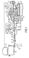
- the fuel system of an internal combustion engine shown in Fig. 1 includes a liquid fuel feeding circuit comprising a a gasoline tank 1 connected by a gasoline pipe line 2 through a gasoline feed pump (not shown in the drawing) to a float chamber 3 of a carburettor 4, the float chamber being connected through fuel jets 5 (shown schematically in the drawing is only one jet of a primary chamber) to corresponding nozzles 6 and 7 of primary and secondary chambers (shown schematically in the drawing is only the primary chamber) of the carburettor 4.
- the float chamber 3 is also connected to a passage 8 to feed liquid fuel when idling.
- the passage 8 through which liquid fuel is fed during idling is, in turn, connected to an intake manifold 9 of an engine 10 through a metering orifice 11 of a solenoid-operated valve (not shown in the drawing).
- a fuel gas feeding circuit comprises a stationary gas cylinder 12 connected to a charging device 13 and to a main gas pipe line 14. Connected one after another downstream thereof to the main gas pipe line are a filter 15, a heater 16 to which inlet and outlet conduits 17 are connected to ensure the circulation of cooling liquid through the heater 16 from the cooling system of the engine 10.
- an adjustable gas pressure reducer 18 Connected further downstream to the outlet of the heater 16 is an adjustable gas pressure reducer 18 which is provided with a pressure gauge 18' and is made so that it is a single-stage pressure reducer having a membrane made from an oil and gasoline resistant rubber of (2-5) mm in thickness, and then to a shutoff valve 19 having a control circuit 20.
- the shutoff valve 19 is connected through the main gas pipe line 14 to a controllable distributing unit 21 which has one outlet thereof communicated with a passage 22 to feed combustible mixture when idling and another outlet thereof communicated with the intake manifold 9 of the engine 10.
- the control circuit 20 comprises a generator relay 23, a a control relay 24 and a signalling lamp 25.
- the controllable distributing unit 21 comprises an idling gas pipe line 26 connecting the main gas pipe line to a first outlet of the unit 21, a medium-load gas pipe line 27 connecting the main gas pipe line 14 to a second output of the unit 21 through a jet 28, and a maximum-load gas pipe line 29 connecting the main gas pipe line 14 to the second outlet through an elbow 30 of a tee-joint 31.
- the controllable distributing unit 21 includes also a transient-duty and medium-load valve 32 mounted in the gas pipe line 27, a maximum-load valve 33 mounted in the maximum-load gas pipe line 29, as well as microswitches 34 and 35 connected to control inputs of the valves 32 and 33, respectively, and electrically connected to an engine speed control pedal (not shown in the drawing) coupled with a throttle valve 36, and a pressure-operated electrical unit 37 mounted in the gas pipe line 26.
- the fuel system is made such that the cross-sectional areas of the main fuel jets of the carburettor are reduced 2.5-3.5 times and the cross-sectional areas of the main air jets are reduced 4.0-6.0 times as compared with traditional internal combustion engines using a fuel system operating with gasoline-air mixture.
- Fig. 2 shows a cross section of the filter 15 which consists of a filter casing 38, covers 39, a sealing ring 40, distance sleeves 41 and filter elements 42.
- the multistage filter being included in the fuel gas feeding circuit allows to carry out both coarse and fine cleaning of gases, thus removing impurities therefrom - a factor which guarantees normal operation of the pressure reducer, ensuring meanwhile a 100% utilization of the fuel gas. Accumulation of various impurities in the filter in the form of dry powder (upstream an evaporator) prevents the system from fouling with viscous gummy fractions which can be formed at elevated temperatures of fuel gas.
- the filter is cleaned and its serviceability is restored automatically as the locking element is opened in the charging device (with the gas cylinder being disconnected) when the accumulated powdery impurities are blown outside under pressure. So the filter is cleaned by back pressure.
- Fig. 3 shows a cross section of the heater 16 which comprises a heater housing 43, covers 44 and 45, inlet and outlet pipe connections 46 and 47 to ensure the circulation of cooling liquid therethrough from the cooling system of the engine.
- the main gas pipe line 14 extends through the housing 43 of the heater.
- the heater has a fuel heating surface area of as much as (7.0 ⁇ 1.0) ⁇ 10 -3 m 2 .
- the heating surface area for heating up the liquid phase of fuel gas in the heater has been selected such that it is possible to obtain the gaseous phase of fuel gas having such parameters which ensure an optimum composition of combustible mixture.
- the heater has a simpler design than the known heaters of this type, and the technology of manufacturing this heater is very simple.
- Fig. 4 shows a cross section of the pressure-operated electrical unit which comprises:
- the pressure-operated electrical unit of Fig. 4 is designed to cut out or in the solenoid-operated valve of the carburettor, thus ensuring the feed of liquid fuel, when idling through the orifice 11 into the passage 22 for feeding combustible mixture while idling. Voltage is applied to the fixed contact 51. When there is fuel gas under pressure of 0.1-0.2 MPa in the cavity 57, the movable contact 55 is released, the circuit is open between the contacts 50 and 51, no voltage is supplied to the solenoid-operated valve of the carburettor, and it shuts off the feed of liquid fuel into the idling system.
- This fuel system of the internal combustion engine operates as follows.
- the liquid phase of fuel gas is fed under pressure of 1.2-1.6 MPa over the main gas pipe line 14 through the multistage filter 15 and the heater 16 where it is heated up to reach essentially the temperature of cooling liquid in the engine, into the adjustable gas pressure reducer 18, by means of which the start-up operating pressure is set which is equal to 0.02-0.1 MPa.
- Ignition is switched on, the pedal-controlled throttle valve 36 is slightly opened, the starter is switched on, and the engine 10 is started up.
- the generator which is not shown in the drawing begins to generate voltage which is supplied to the contacts of the generator relay 23 and to the control relay 24.
- the shutoff valve 19 gets actuated. With the shutoff valve being open, gas will flow simultaneously over the passage 26 through the metering orifice 53' of the pressure-operated electrical unit 37 into the passage 22 and therefrom into the intake manifold 9, and over the gas pipe line 27 through the jet 28 into the intake manifold 9 of the engine 10.
- the microswitch 34 With the throttle valve 36 being open, the microswitch 34 will operate to open the transient-duty and medium-load valve 32, so that fuel will flow over the gas pipe line 27 through the jet 38 of the tee-joint 31 into the space behind the throttle valve in the intake manifold 9.
- the fuel system allows to warm up the engine with an open air throttle 58 even at below-zero temperatures.
- the heated cooling liquid will flow from the cooling system over the conduit 17 into the heater 16 through the pipe connections 46 and 47, Fig. 3, to transfer the liquid phase of fuel gas into a new consistency state.
- the pressure reducer 18 will set the operating pressure which is equal to 0.08-0.2 MPa.
- the liquid phase of fuel gas heated up in the heater 16 to reach a predetermined consistency state is fed under pressure of 0.08-0.2 MPa over supplementary gas pipe lines 26 and 27 into the space behind the throttle valve in the intake manifold, where it gets mixed with gasoline-air mixture, thus forming an optimum dual-fuel combustible mixture so that operation of the engine without drops is ensured at all transient modes.
- the microswitch 35 will operate to open the maximum-load valve 33, so that fuel gas will flow through the tee-joint 31 under pressure of 0.08-0.2 MPa into the space behind the throttle valve, thus enriching additionally combustible mixture.
- the disclosed fuel system for engines has the following main advantages:
- the fuel system has been tested in a Model VAZ 2106 car.
- the distance run without refuelling (39 liters of A76 gasoline and 40 liters of propane-butane gas) is ⁇ (800-850) km in city service, and ⁇ (950-1000) km on highway.
- Time for standing-start acceleration to a speed of 100 km/hour with a load of ⁇ 250 kg (a driver and two passengers) is 14-15 s.
- the fuel system for an internal combustion engine can be used for the feed of any internal combustion engines, and preferably - for carburettor engines.
Landscapes
- Engineering & Computer Science (AREA)
- Chemical & Material Sciences (AREA)
- Combustion & Propulsion (AREA)
- Mechanical Engineering (AREA)
- General Engineering & Computer Science (AREA)
- Oil, Petroleum & Natural Gas (AREA)
- Chemical Kinetics & Catalysis (AREA)
- General Chemical & Material Sciences (AREA)
- Output Control And Ontrol Of Special Type Engine (AREA)
- Electrical Control Of Air Or Fuel Supplied To Internal-Combustion Engine (AREA)
Applications Claiming Priority (1)
| Application Number | Priority Date | Filing Date | Title |
|---|---|---|---|
| PCT/RU1996/000199 WO1998003786A1 (fr) | 1993-08-06 | 1996-07-22 | Systeme d'alimentation pour moteur a combustion interne |
Publications (2)
| Publication Number | Publication Date |
|---|---|
| EP0915247A1 true EP0915247A1 (fr) | 1999-05-12 |
| EP0915247A4 EP0915247A4 (fr) | 2000-09-06 |
Family
ID=20130017
Family Applications (1)
| Application Number | Title | Priority Date | Filing Date |
|---|---|---|---|
| EP96937600A Withdrawn EP0915247A4 (fr) | 1996-07-22 | 1996-07-22 | Systeme d'alimentation pour moteur a combustion interne |
Country Status (5)
| Country | Link |
|---|---|
| EP (1) | EP0915247A4 (fr) |
| JP (1) | JP2000514900A (fr) |
| AU (1) | AU7510296A (fr) |
| CA (1) | CA2261648A1 (fr) |
| WO (1) | WO1998003786A1 (fr) |
Cited By (1)
| Publication number | Priority date | Publication date | Assignee | Title |
|---|---|---|---|---|
| FR2855852A1 (fr) * | 2003-06-04 | 2004-12-10 | Interlude | Dispositif de raccord multifonction modulable permettant de gerer de maniere optimum l'alimentation en gaz (gpl, gnv ou autres) des injecteurs d'un moteur a explosion d'un vehicule |
Families Citing this family (1)
| Publication number | Priority date | Publication date | Assignee | Title |
|---|---|---|---|---|
| CN102080598B (zh) * | 2010-12-20 | 2012-06-27 | 北京工业大学 | 一种采用二甲醚和高辛烷值燃料内燃机的控制方法 |
Family Cites Families (9)
| Publication number | Priority date | Publication date | Assignee | Title |
|---|---|---|---|---|
| GB2129874A (en) * | 1982-11-09 | 1984-05-23 | David Keith Williams | Fuel system for internal combustion engine |
| SU1370279A1 (ru) | 1986-08-29 | 1988-01-30 | Киевский Автомобильно-Дорожный Институт Им.60-Летия Великой Октябрьской Социалистической Революции | Двухтопливна система питани карбюраторного двигател внутреннего сгорани |
| US4878475A (en) * | 1988-11-21 | 1989-11-07 | Ludwig Birsa | Fuel supply system for internal combustion engines |
| SU1607692A3 (ru) | 1989-01-26 | 1990-11-15 | Karpenko Yurij M | Система питани двигател внутреннего сгорани Карпенко |
| SU1698473A1 (ru) * | 1989-05-03 | 1991-12-15 | Латвийская сельскохозяйственная академия | Система питани газового двигател внутреннего сгорани |
| SU1746023A1 (ru) * | 1989-05-31 | 1992-07-07 | Kablukov Valentin | Устройство топливоподачи дл двигател внутреннего сгорани |
| SU1740744A1 (ru) * | 1989-10-05 | 1992-06-15 | Научно-производственное объединение "Кибернетика" | Газова система питани дл двигател внутреннего сгорани |
| SU1653545A3 (ru) * | 1989-12-27 | 1991-05-30 | Dmitrij V Zadorozhnyj | Система подачи газового топлива для двигателя внутреннего сгорания |
| US5411058A (en) * | 1992-12-22 | 1995-05-02 | Welsh; James W. | Method and apparatus for utilizing gaseous and liquid fuels in an internal combustion device |
-
1996
- 1996-07-22 WO PCT/RU1996/000199 patent/WO1998003786A1/fr not_active Ceased
- 1996-07-22 AU AU75102/96A patent/AU7510296A/en not_active Abandoned
- 1996-07-22 CA CA002261648A patent/CA2261648A1/fr not_active Abandoned
- 1996-07-22 EP EP96937600A patent/EP0915247A4/fr not_active Withdrawn
- 1996-07-22 JP JP10506845A patent/JP2000514900A/ja active Pending
Cited By (1)
| Publication number | Priority date | Publication date | Assignee | Title |
|---|---|---|---|---|
| FR2855852A1 (fr) * | 2003-06-04 | 2004-12-10 | Interlude | Dispositif de raccord multifonction modulable permettant de gerer de maniere optimum l'alimentation en gaz (gpl, gnv ou autres) des injecteurs d'un moteur a explosion d'un vehicule |
Also Published As
| Publication number | Publication date |
|---|---|
| WO1998003786A1 (fr) | 1998-01-29 |
| CA2261648A1 (fr) | 1998-01-29 |
| EP0915247A4 (fr) | 2000-09-06 |
| JP2000514900A (ja) | 2000-11-07 |
| AU7510296A (en) | 1998-02-10 |
Similar Documents
| Publication | Publication Date | Title |
|---|---|---|
| US4548187A (en) | Internal combustion engine for alternative fuels | |
| US4335697A (en) | Internal combustion engine dual fuel system | |
| US4398523A (en) | Fuel conservation device | |
| US4531497A (en) | Natural gas adaptor system for automobiles | |
| GB1580158A (en) | Pre-vaporising fuel system | |
| US3948224A (en) | System to prevent pollution of atmosphere | |
| US20050252489A1 (en) | Variable octane duel fuel delivery system | |
| US4611557A (en) | Internal-combustion engine | |
| WO2013009597A2 (fr) | Système de carburant pour automobile | |
| EP0915247A1 (fr) | Systeme d'alimentation pour moteur a combustion interne | |
| US4386593A (en) | Fuel-air injection control system for internal combustion engines | |
| RU2087738C1 (ru) | Система питания двигателей внутреннего сгорания конструкции чумакова | |
| RU2006621C1 (ru) | Система питания двигателя внутреннего сгорания с двумя видами топлива | |
| US5555852A (en) | Alcohol injection system and method for internal combustion engines | |
| RU2074970C1 (ru) | Способ питания двигателей внутреннего сгорания чумакова | |
| CN86210785U (zh) | 汽车燃烧液化石油气的系统装置 | |
| KR20000029461A (ko) | 내연기관의연료시스템 | |
| AU2008303790A1 (en) | Supply device for internal combustion engine | |
| SU1607692A3 (ru) | Система питани двигател внутреннего сгорани Карпенко | |
| SU1618285A3 (ru) | Система питани двигател внутреннего сгорани | |
| CN1224483A (zh) | 内燃机的燃料供应系统 | |
| CA1234026A (fr) | Moteur a combustion interne | |
| SU1746023A1 (ru) | Устройство топливоподачи дл двигател внутреннего сгорани | |
| RU2136940C1 (ru) | Система питания карбюраторного двигателя | |
| CN2380709Y (zh) | 内燃机蒸汽节油装置 |
Legal Events
| Date | Code | Title | Description |
|---|---|---|---|
| PUAI | Public reference made under article 153(3) epc to a published international application that has entered the european phase |
Free format text: ORIGINAL CODE: 0009012 |
|
| 17P | Request for examination filed |
Effective date: 19990129 |
|
| AK | Designated contracting states |
Kind code of ref document: A1 Designated state(s): AT BE CH DE DK ES FI FR GB GR IE IT LI LU MC NL PT SE |
|
| STAA | Information on the status of an ep patent application or granted ep patent |
Free format text: STATUS: THE APPLICATION IS DEEMED TO BE WITHDRAWN |
|
| 18D | Application deemed to be withdrawn |
Effective date: 20000201 |
|
| A4 | Supplementary search report drawn up and despatched |
Effective date: 20000721 |
|
| AK | Designated contracting states |
Kind code of ref document: A4 Designated state(s): AT BE CH DE DK ES FI FR GB GR IE IT LI LU MC NL PT SE |