EP0915260A1 - Befestigungsverfahren für ein Führungsglied auf einem Träger, nach diesem Verfahren hergestellte Führungseinrichtung und Markierungsgerät mit einer solchen Vorrichtung - Google Patents
Befestigungsverfahren für ein Führungsglied auf einem Träger, nach diesem Verfahren hergestellte Führungseinrichtung und Markierungsgerät mit einer solchen Vorrichtung Download PDFInfo
- Publication number
- EP0915260A1 EP0915260A1 EP98420199A EP98420199A EP0915260A1 EP 0915260 A1 EP0915260 A1 EP 0915260A1 EP 98420199 A EP98420199 A EP 98420199A EP 98420199 A EP98420199 A EP 98420199A EP 0915260 A1 EP0915260 A1 EP 0915260A1
- Authority
- EP
- European Patent Office
- Prior art keywords
- guide member
- opening
- support
- guide
- bar
- Prior art date
- Legal status (The legal status is an assumption and is not a legal conclusion. Google has not performed a legal analysis and makes no representation as to the accuracy of the status listed.)
- Granted
Links
- 238000000034 method Methods 0.000 title claims abstract description 12
- 229920005989 resin Polymers 0.000 claims abstract description 27
- 239000011347 resin Substances 0.000 claims abstract description 27
- 230000000379 polymerizing effect Effects 0.000 claims abstract 2
- 210000000056 organ Anatomy 0.000 claims description 3
- 239000011248 coating agent Substances 0.000 claims description 2
- 238000000576 coating method Methods 0.000 claims description 2
- 230000003100 immobilizing effect Effects 0.000 claims description 2
- 238000011065 in-situ storage Methods 0.000 claims description 2
- 239000007787 solid Substances 0.000 claims description 2
- 239000011229 interlayer Substances 0.000 claims 2
- 239000002966 varnish Substances 0.000 description 8
- 238000003754 machining Methods 0.000 description 4
- 238000006116 polymerization reaction Methods 0.000 description 3
- 238000012423 maintenance Methods 0.000 description 2
- 239000004593 Epoxy Substances 0.000 description 1
- 238000005266 casting Methods 0.000 description 1
- 238000004140 cleaning Methods 0.000 description 1
- 238000006073 displacement reaction Methods 0.000 description 1
- 230000000694 effects Effects 0.000 description 1
- 238000004519 manufacturing process Methods 0.000 description 1
- 239000000463 material Substances 0.000 description 1
- 229920000647 polyepoxide Polymers 0.000 description 1
- 229920005749 polyurethane resin Polymers 0.000 description 1
- 238000007789 sealing Methods 0.000 description 1
Images

Classifications
-
- F—MECHANICAL ENGINEERING; LIGHTING; HEATING; WEAPONS; BLASTING
- F16—ENGINEERING ELEMENTS AND UNITS; GENERAL MEASURES FOR PRODUCING AND MAINTAINING EFFECTIVE FUNCTIONING OF MACHINES OR INSTALLATIONS; THERMAL INSULATION IN GENERAL
- F16C—SHAFTS; FLEXIBLE SHAFTS; ELEMENTS OR CRANKSHAFT MECHANISMS; ROTARY BODIES OTHER THAN GEARING ELEMENTS; BEARINGS
- F16C29/00—Bearings for parts moving only linearly
- F16C29/12—Arrangements for adjusting play
-
- F—MECHANICAL ENGINEERING; LIGHTING; HEATING; WEAPONS; BLASTING
- F16—ENGINEERING ELEMENTS AND UNITS; GENERAL MEASURES FOR PRODUCING AND MAINTAINING EFFECTIVE FUNCTIONING OF MACHINES OR INSTALLATIONS; THERMAL INSULATION IN GENERAL
- F16B—DEVICES FOR FASTENING OR SECURING CONSTRUCTIONAL ELEMENTS OR MACHINE PARTS TOGETHER, e.g. NAILS, BOLTS, CIRCLIPS, CLAMPS, CLIPS OR WEDGES; JOINTS OR JOINTING
- F16B11/00—Connecting constructional elements or machine parts by sticking or pressing them together, e.g. cold pressure welding
- F16B11/006—Connecting constructional elements or machine parts by sticking or pressing them together, e.g. cold pressure welding by gluing
- F16B11/008—Connecting constructional elements or machine parts by sticking or pressing them together, e.g. cold pressure welding by gluing of tubular elements or rods in coaxial engagement
-
- F—MECHANICAL ENGINEERING; LIGHTING; HEATING; WEAPONS; BLASTING
- F16—ENGINEERING ELEMENTS AND UNITS; GENERAL MEASURES FOR PRODUCING AND MAINTAINING EFFECTIVE FUNCTIONING OF MACHINES OR INSTALLATIONS; THERMAL INSULATION IN GENERAL
- F16C—SHAFTS; FLEXIBLE SHAFTS; ELEMENTS OR CRANKSHAFT MECHANISMS; ROTARY BODIES OTHER THAN GEARING ELEMENTS; BEARINGS
- F16C29/00—Bearings for parts moving only linearly
- F16C29/02—Sliding-contact bearings
-
- Y—GENERAL TAGGING OF NEW TECHNOLOGICAL DEVELOPMENTS; GENERAL TAGGING OF CROSS-SECTIONAL TECHNOLOGIES SPANNING OVER SEVERAL SECTIONS OF THE IPC; TECHNICAL SUBJECTS COVERED BY FORMER USPC CROSS-REFERENCE ART COLLECTIONS [XRACs] AND DIGESTS
- Y10—TECHNICAL SUBJECTS COVERED BY FORMER USPC
- Y10T—TECHNICAL SUBJECTS COVERED BY FORMER US CLASSIFICATION
- Y10T403/00—Joints and connections
- Y10T403/32—Articulated members
- Y10T403/32606—Pivoted
- Y10T403/32861—T-pivot, e.g., wrist pin, etc.
- Y10T403/32877—Pin is integral with or secured to inner member
-
- Y—GENERAL TAGGING OF NEW TECHNOLOGICAL DEVELOPMENTS; GENERAL TAGGING OF CROSS-SECTIONAL TECHNOLOGIES SPANNING OVER SEVERAL SECTIONS OF THE IPC; TECHNICAL SUBJECTS COVERED BY FORMER USPC CROSS-REFERENCE ART COLLECTIONS [XRACs] AND DIGESTS
- Y10—TECHNICAL SUBJECTS COVERED BY FORMER USPC
- Y10T—TECHNICAL SUBJECTS COVERED BY FORMER US CLASSIFICATION
- Y10T403/00—Joints and connections
- Y10T403/32—Articulated members
- Y10T403/32606—Pivoted
- Y10T403/32861—T-pivot, e.g., wrist pin, etc.
- Y10T403/32893—T-pivot, e.g., wrist pin, etc. including distinct pin retainer
-
- Y—GENERAL TAGGING OF NEW TECHNOLOGICAL DEVELOPMENTS; GENERAL TAGGING OF CROSS-SECTIONAL TECHNOLOGIES SPANNING OVER SEVERAL SECTIONS OF THE IPC; TECHNICAL SUBJECTS COVERED BY FORMER USPC CROSS-REFERENCE ART COLLECTIONS [XRACs] AND DIGESTS
- Y10—TECHNICAL SUBJECTS COVERED BY FORMER USPC
- Y10T—TECHNICAL SUBJECTS COVERED BY FORMER US CLASSIFICATION
- Y10T403/00—Joints and connections
- Y10T403/32—Articulated members
- Y10T403/32606—Pivoted
- Y10T403/32951—Transverse pin or stud
- Y10T403/32967—Attached to or integral with one member
-
- Y—GENERAL TAGGING OF NEW TECHNOLOGICAL DEVELOPMENTS; GENERAL TAGGING OF CROSS-SECTIONAL TECHNOLOGIES SPANNING OVER SEVERAL SECTIONS OF THE IPC; TECHNICAL SUBJECTS COVERED BY FORMER USPC CROSS-REFERENCE ART COLLECTIONS [XRACs] AND DIGESTS
- Y10—TECHNICAL SUBJECTS COVERED BY FORMER USPC
- Y10T—TECHNICAL SUBJECTS COVERED BY FORMER US CLASSIFICATION
- Y10T403/00—Joints and connections
- Y10T403/47—Molded joint
- Y10T403/472—Molded joint including mechanical interlock
Definitions
- the present invention relates to a fixing method a guide member on a support.
- the quality of expected geometry is not always obtained after assembly executed.
- the marking device is susceptible deform under the effect of the stresses exerted by the clamping occurring during the corresponding machining, or still under the influence of the tools' rump efforts ensuring this machining.
- the subject of the invention is a method of fixing of a guide member on a support which ensures a precise positioning of these different elements by compared to others, while generating mechanical forces limits.
- the invention relates to a method of fixing of a guide member on a support, in which cleaning in the support at least one opening suitable for receiving one end of the guide member, and we introduce this end in the opening, characterized in that one realizes opening in substantially transverse dimensions greater than those of the end which is received there, we places the guide member in the precise position it must occupy, we thus delimit an intermediate space between the outer periphery of the end and the walls opposite the opening, we fill this intermediate space with a resin polymerizable and said resin is polymerized so to secure the end relative to the opening.
- the relative positioning phase of the guide member and the opening in which it is inserted can be implemented using simple mechanical means, for example example a timing system. This therefore does not induce efforts important likely to alter the geometry of the whole the device once made.
- the polymerizable resin introduced into the intermediate space formed between the guide member and the opening which receives it ensures a reliable fixing of each guide member on the support.
- the invention also relates to a device for guidance obtained according to the above method, comprising at least a guide member fixed on a support, each end of this member being housed in a corresponding opening formed in the support, characterized in that this opening has transverse dimensions substantially greater than those of the end of the guide member, a sheath formed of a solid state polymerizable resin being cast in situ between the outer periphery of this end and the walls next to the opening.
- the invention finally relates to a marking device comprising at least one guide device as described above.
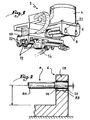
- the marking device shown in Figure 1 and designated as a whole by reference 2 includes, so known per se, a fixed frame 4 comprising two flanges 6 in look supporting two bars 8 constituting organs of guide, for the displacement along the axis of these bars of a first carriage 10.
- the latter is also provided with two guide bars 12, the two pairs of bars 8, 12 being arranged substantially at right angles.
- the bars 12 guide a second carriage 14 on which is intended to be attached a marking head not shown.
- the two carriages 10, 14 therefore constitute the drive mechanism of the marking device, and ensure positioning of the marking head in two directions orthogonal to each other.
- the respective training of the two carriages 10, 14 is provided, in a manner known per se, by by means of electric motors not shown.
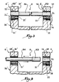
- each bar 8 comprises a cylindrical middle part 8A terminated by two cylindrical ends 8B of larger diameter, of which only one is shown.
- the bar 8 is intended to be fixed to the rim 6 by its ends 8B.
- Each of the latter is received at a cylindrical through opening 16, formed in the rim 6.
- This opening 16 has a transverse dimension, namely a diameter D, which is substantially greater than that of the end 8B, namely its diameter d .
- each end 8B within of the opening 16 it first of all introduce each end 8B within of the opening 16, then position them relatively according to the shape of the marking device once done.
- the bar 8 is maintained by relative to a reference surface of the frame 4, in this case a 6A base rectified beforehand, at distances and according to appropriate guidance. This maintenance can be ensured, by example, by a system of shims. It should be noted that in the example shown, the bar 8 and the opening 16 are not rigorously coaxial.
- the outer periphery of the end 8B defines, with the walls of the opening 16 opposite, an intermediate space Roughly annular. While holding the 8 bar and the ledge 6 in their relative positions mentioned above, we then fills this intermediate space 20 with a resin polymerizable, for example an epoxy or polyurethane resin. We may also plan to use other types of materials equivalent curable.
- a resin polymerizable for example an epoxy or polyurethane resin.
- Figures 3 and 4 illustrate a first variant of realization of the invention.
- Bar 8 which is mounted in two openings 16, 16 'formed in the flanges 6, 6' in look of the frame 4, is similar to that shown in the figure 2.
- the outer periphery of the ends 8B of this bar 8 is covered with a non-stick varnish which allows them to slide freely in the sleeves 21, 21 'of resin filling the designated intermediate spaces by reference 20 in Figure 2.
- the mounting of a new bar on its support is particularly easy. It should first of all be covered the ends with the non-stick varnish. Then, we introduces one end of this bar within the sheath 21 'whose access is not prohibited by the presence of a screw. We then slide this first end in this sheath 21 '. We then pass the part middle, then we slide the second end of this closed off. The latter is then precisely positioned in an axial direction, due to the presence of the screw 22 against which the first end of this new bar comes to a stop. In addition, the latter is perfectly positioned in a transverse direction, due to the presence of the resin shells 21, 21 ′ having served to immobilize the first bar 8. The subjection in translation the new bar is made by replacing the screw 22 ', removed for disassembly of the first bar 8, at its location original.
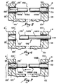
- Figures 5 to 7 illustrate a second variant of realization of the invention.
- the bar 108 differs from that 8 shown in FIGS. 2 to 4, in meaning that each of its ends 108B, 108B 'is provided a distal chamfer 110, 110 ', so that they widen in direction of the middle part 108A.
- Resin sheaths, interposed between the walls of the openings 16, 16 'and the outer periphery of the ends 108B, 108B 'of the bar, with a view to subjugating the latter in relation to the carriage 6, are therefore no longer generally annular like this was the case previously.
- the ends 108B, 108B 'of the bar 108 are covered with a non-stick varnish, this bar is perfectly immobilized both transversely thanks to the annular parts 122, 122 'of the resin sheaths, as well only axially since these ends abut against the pockets 123, 123 'which obstruct the movement of the closed off.
- each end of the new bar is positioned in a transverse direction, thanks to the presence of the annular parts 122, 122 ′ at the into which the ends are introduced.
- the axial positioning of the entire new bar is provided by the pocket 123 'which was not destroyed during the disassembly of the first bar, pocket against which the new bar comes to a stop.
- the subjugation in translation of this new bar is made by pouring a new resin pocket into the location 124 of the pocket 123 previously destroyed.
- Figures 8 and 9 illustrate two additional variants of the invention.
- the bar 208 presents a constant diameter over its entire length.
- the outer periphery of its ends 208B, 208B ' is not covered with a non-stick varnish, but is surrounded by an annular ring 228, for example metallic.
- the bar 308 also has a diameter constant over its entire length. Its ends 308B, 308B ' include a chamfer 310. The outer periphery of its ends 308B, 308B 'is not covered with non-stick varnish, but is surrounded by a chamfered ring 328 of which the profile is conjugated with that of the ends 308B, 308B '.
- the bar 308 is sealed to support 6 while being provided with these rings 328, by casting sheaths of resins 321, 321 'analogous to those represented in FIGS. 5 to 7.
Landscapes
- Engineering & Computer Science (AREA)
- General Engineering & Computer Science (AREA)
- Mechanical Engineering (AREA)
- Road Signs Or Road Markings (AREA)
- Adornments (AREA)
- Slide Fasteners, Snap Fasteners, And Hook Fasteners (AREA)
- Casting Or Compression Moulding Of Plastics Or The Like (AREA)
- Perforating, Stamping-Out Or Severing By Means Other Than Cutting (AREA)
- Lining Or Joining Of Plastics Or The Like (AREA)
- Telephone Function (AREA)
- Standing Axle, Rod, Or Tube Structures Coupled By Welding, Adhesion, Or Deposition (AREA)
- Pens And Brushes (AREA)
- Sheet Holders (AREA)
- Fishing Rods (AREA)
- Impact Printers (AREA)
- Geophysics And Detection Of Objects (AREA)
Applications Claiming Priority (2)
| Application Number | Priority Date | Filing Date | Title |
|---|---|---|---|
| FR9714180 | 1997-11-05 | ||
| FR9714180A FR2770431B1 (fr) | 1997-11-05 | 1997-11-05 | Procede de fixation d'un organe de guidage sur un support, dispositif de guidage obtenu par ce procede et appareil de marquage comprenant un tel dispositif |
Publications (2)
| Publication Number | Publication Date |
|---|---|
| EP0915260A1 true EP0915260A1 (de) | 1999-05-12 |
| EP0915260B1 EP0915260B1 (de) | 2002-12-18 |
Family
ID=9513285
Family Applications (1)
| Application Number | Title | Priority Date | Filing Date |
|---|---|---|---|
| EP98420199A Expired - Lifetime EP0915260B1 (de) | 1997-11-05 | 1998-11-04 | Befestigungsverfahren für ein Führungsglied auf einem Träger, nach diesem Verfahren hergestellte Führungseinrichtung und Markierungsgerät mit einer solchen Vorrichtung |
Country Status (11)
| Country | Link |
|---|---|
| US (1) | US6309133B1 (de) |
| EP (1) | EP0915260B1 (de) |
| JP (1) | JPH11230129A (de) |
| CN (1) | CN1117220C (de) |
| AT (1) | ATE230074T1 (de) |
| BR (1) | BR9804561A (de) |
| CA (1) | CA2252172A1 (de) |
| DE (1) | DE69810246T2 (de) |
| DK (1) | DK0915260T3 (de) |
| ES (1) | ES2185129T3 (de) |
| FR (1) | FR2770431B1 (de) |
Cited By (2)
| Publication number | Priority date | Publication date | Assignee | Title |
|---|---|---|---|---|
| EP1130277A1 (de) * | 2000-03-01 | 2001-09-05 | Marie-Christine Curreno | Montageverfahren einer Antriebslaufkatze eines Markierungsapparates auf eine Führungsvorrichtung,und zugehöriger Markierungsapparat |
| EP1369606A1 (de) | 2002-06-06 | 2003-12-10 | Technifor | Markierungsapparat mit mindestens einer Führungsvorrichtung und mindestens einer Antriebslaufkatze |
Families Citing this family (2)
| Publication number | Priority date | Publication date | Assignee | Title |
|---|---|---|---|---|
| FR2848499A1 (fr) | 2002-12-11 | 2004-06-18 | Technifor | Dispositif de marquage a l'aide d'un organe de marquage potentiellement dangereux pour un utilisateur |
| EP3803257A4 (de) | 2018-06-08 | 2022-04-06 | Sheltered Wings, Inc. D/b/a/ Vortex Optics | Selbstzentrierendes führungsgestänge für einen gewehringsturm |
Citations (3)
| Publication number | Priority date | Publication date | Assignee | Title |
|---|---|---|---|---|
| FR2109232A5 (de) * | 1970-10-06 | 1972-05-26 | Pont A Mousson | |
| US4620814A (en) * | 1983-10-24 | 1986-11-04 | Jim May | Device with distortable opening-defining portion |
| US5002411A (en) * | 1988-12-01 | 1991-03-26 | Technifor | Apparatus for marking objects by a vibrating tool |
Family Cites Families (4)
| Publication number | Priority date | Publication date | Assignee | Title |
|---|---|---|---|---|
| DE2525579A1 (de) * | 1975-06-09 | 1976-12-30 | Hilti Ag | Klebeanker |
| DE3519679A1 (de) * | 1985-06-01 | 1986-12-04 | Beitz, Wolfgang, Prof.Dr.-Ing. | Verfahren zur herstellung loesbarer verbindungen (schrauben-, formschluessige welle-nabe- und linienhafte formschlussverbindungen) durch formelemente aus klebstoff |
| DE4112531A1 (de) * | 1991-04-17 | 1992-10-22 | Bayer Ag | Verbundanker mit wasserhaertender polymerzubereitung |
| US5368400A (en) * | 1993-10-15 | 1994-11-29 | Telesis Marking Systems, Inc. | Marking apparatus with cable drive |
-
1997
- 1997-11-05 FR FR9714180A patent/FR2770431B1/fr not_active Expired - Fee Related
-
1998
- 1998-10-27 CA CA002252172A patent/CA2252172A1/fr not_active Abandoned
- 1998-10-30 US US09/182,496 patent/US6309133B1/en not_active Expired - Fee Related
- 1998-11-04 ES ES98420199T patent/ES2185129T3/es not_active Expired - Lifetime
- 1998-11-04 EP EP98420199A patent/EP0915260B1/de not_active Expired - Lifetime
- 1998-11-04 DE DE69810246T patent/DE69810246T2/de not_active Expired - Fee Related
- 1998-11-04 DK DK98420199T patent/DK0915260T3/da active
- 1998-11-04 AT AT98420199T patent/ATE230074T1/de not_active IP Right Cessation
- 1998-11-04 CN CN98123838.6A patent/CN1117220C/zh not_active Expired - Fee Related
- 1998-11-05 JP JP10315117A patent/JPH11230129A/ja not_active Withdrawn
- 1998-11-05 BR BR9804561-0A patent/BR9804561A/pt not_active IP Right Cessation
Patent Citations (3)
| Publication number | Priority date | Publication date | Assignee | Title |
|---|---|---|---|---|
| FR2109232A5 (de) * | 1970-10-06 | 1972-05-26 | Pont A Mousson | |
| US4620814A (en) * | 1983-10-24 | 1986-11-04 | Jim May | Device with distortable opening-defining portion |
| US5002411A (en) * | 1988-12-01 | 1991-03-26 | Technifor | Apparatus for marking objects by a vibrating tool |
Cited By (4)
| Publication number | Priority date | Publication date | Assignee | Title |
|---|---|---|---|---|
| EP1130277A1 (de) * | 2000-03-01 | 2001-09-05 | Marie-Christine Curreno | Montageverfahren einer Antriebslaufkatze eines Markierungsapparates auf eine Führungsvorrichtung,und zugehöriger Markierungsapparat |
| FR2805867A1 (fr) * | 2000-03-01 | 2001-09-07 | Marie Christine Curreno | Procede de montage d'un chariot d'entrainement d'un appareil de marquage sur au moins un organe de guidage, et appareil de marquage correspondant |
| US6602005B2 (en) | 2000-03-01 | 2003-08-05 | Technifor | Process for assembling a carriage for driving a marking apparatus on at least one guide member, and corresponding marking apparatus |
| EP1369606A1 (de) | 2002-06-06 | 2003-12-10 | Technifor | Markierungsapparat mit mindestens einer Führungsvorrichtung und mindestens einer Antriebslaufkatze |
Also Published As
| Publication number | Publication date |
|---|---|
| DE69810246T2 (de) | 2003-08-28 |
| FR2770431B1 (fr) | 1999-12-31 |
| ES2185129T3 (es) | 2003-04-16 |
| DK0915260T3 (da) | 2003-07-21 |
| US6309133B1 (en) | 2001-10-30 |
| FR2770431A1 (fr) | 1999-05-07 |
| JPH11230129A (ja) | 1999-08-27 |
| CN1117220C (zh) | 2003-08-06 |
| BR9804561A (pt) | 2004-08-24 |
| ATE230074T1 (de) | 2003-01-15 |
| EP0915260B1 (de) | 2002-12-18 |
| CN1216805A (zh) | 1999-05-19 |
| DE69810246D1 (de) | 2003-01-30 |
| CA2252172A1 (fr) | 1999-05-05 |
Similar Documents
| Publication | Publication Date | Title |
|---|---|---|
| FR2811404A1 (fr) | Systeme d'assemblage verrouillable et deverrouillable de deux pieces tubulaires | |
| FR2972963A1 (fr) | Element de suspension pour machine automotrice | |
| EP0219404B1 (de) | Innenbearbeitungsvorrichtung für eine Röhre | |
| EP0915260B1 (de) | Befestigungsverfahren für ein Führungsglied auf einem Träger, nach diesem Verfahren hergestellte Führungseinrichtung und Markierungsgerät mit einer solchen Vorrichtung | |
| FR2498502A1 (fr) | Outil de percage a plaques de coupe amovible | |
| LU83084A1 (fr) | Dispositif pour supporter le bain de soudure de premiere passe dans le soudage en bout automatique de tubes | |
| FR2601284A1 (fr) | Machine de moulage par soufflage, equipee d'un dispositif de calibrage. | |
| FR2593565A1 (fr) | Ensemble cylindre-piston pourvu d'un axe de pivotement | |
| FR2481398A1 (fr) | Transmission par chaine de precision | |
| FR2546966A1 (fr) | Procede de fabrication d'un ensemble d'ailettes de stator soudees pour turbomachine et ensemble en resultant | |
| CA2495247C (fr) | Procede, dispositif et machine d'essai de flexion pure eventuellement alternee | |
| EP0403434A1 (de) | Verfahren zum Vorbereiten sowie Befestigen und Vorrichtung zum Befestigen von Druckplatten auf dem Plattenzylinder einer Tiefdruckmaschine | |
| EP0452216A1 (de) | Gerät zum Scherprüfung von Prüflingen | |
| EP2648877B1 (de) | Klemm-/löseflansch | |
| FR2466296A1 (fr) | Nez de broche pour machines-outils | |
| FR2593564A1 (fr) | Ensemble cylindre-piston equipe de detecteurs de proximite de position reglable | |
| EP0262998A1 (de) | Bohrvorrichtung für Holzpaneele und ihr Zusammenbau durch Dübeln | |
| FR2805867A1 (fr) | Procede de montage d'un chariot d'entrainement d'un appareil de marquage sur au moins un organe de guidage, et appareil de marquage correspondant | |
| EP4188253B1 (de) | Osteosynthesevorrichtung mit mindestens einem fixationsstift | |
| EP4171888B1 (de) | Werkzeugsatz zur befestigung eines schutzmittels unter einem fahrzeug und zugehöriges montageverfahren | |
| EP4632344A1 (de) | Vorrichtung zur steuerung der spannung einer befestigung und steuerungsverfahren dafür | |
| FR2911525A1 (fr) | Dispositif de centrage pour un pare-brise d'un vehicule automobile comprenant des moyens de calage mobiles. | |
| EP0992316A1 (de) | Handbetätigte Vorrichtung zur Richtigstellung der Position einer Elektrospindels bezüglich eines Trägers | |
| WO2026068824A1 (fr) | Dispositif de contrôle par ultrasons d'une soudure comprenant une ceinture de supports, et procédé associé | |
| EP0037754A1 (de) | Vorrichtung zum Korrigieren des Standes einer durch einen Zylinder einer Druckmaschine getragenen Druckplatte |
Legal Events
| Date | Code | Title | Description |
|---|---|---|---|
| PUAI | Public reference made under article 153(3) epc to a published international application that has entered the european phase |
Free format text: ORIGINAL CODE: 0009012 |
|
| AK | Designated contracting states |
Kind code of ref document: A1 Designated state(s): AT BE CH DE DK ES FI FR GB IT LI NL SE |
|
| AX | Request for extension of the european patent |
Free format text: AL;LT;LV;MK;RO;SI |
|
| 17P | Request for examination filed |
Effective date: 19990617 |
|
| AKX | Designation fees paid |
Free format text: AT BE CH DE DK ES FI FR GB IT LI NL SE |
|
| AXX | Extension fees paid |
Free format text: RO PAYMENT 19990617 |
|
| GRAG | Despatch of communication of intention to grant |
Free format text: ORIGINAL CODE: EPIDOS AGRA |
|
| 17Q | First examination report despatched |
Effective date: 20020502 |
|
| GRAG | Despatch of communication of intention to grant |
Free format text: ORIGINAL CODE: EPIDOS AGRA |
|
| GRAH | Despatch of communication of intention to grant a patent |
Free format text: ORIGINAL CODE: EPIDOS IGRA |
|
| GRAH | Despatch of communication of intention to grant a patent |
Free format text: ORIGINAL CODE: EPIDOS IGRA |
|
| GRAA | (expected) grant |
Free format text: ORIGINAL CODE: 0009210 |
|
| AK | Designated contracting states |
Kind code of ref document: B1 Designated state(s): AT BE CH DE DK ES FI FR GB IT LI NL SE |
|
| AX | Request for extension of the european patent |
Free format text: RO PAYMENT 19990617 |
|
| PG25 | Lapsed in a contracting state [announced via postgrant information from national office to epo] |
Ref country code: FI Free format text: LAPSE BECAUSE OF FAILURE TO SUBMIT A TRANSLATION OF THE DESCRIPTION OR TO PAY THE FEE WITHIN THE PRESCRIBED TIME-LIMIT Effective date: 20021218 Ref country code: AT Free format text: LAPSE BECAUSE OF FAILURE TO SUBMIT A TRANSLATION OF THE DESCRIPTION OR TO PAY THE FEE WITHIN THE PRESCRIBED TIME-LIMIT Effective date: 20021218 |
|
| REF | Corresponds to: |
Ref document number: 230074 Country of ref document: AT Date of ref document: 20030115 Kind code of ref document: T |
|
| REG | Reference to a national code |
Ref country code: GB Ref legal event code: FG4D Free format text: NOT ENGLISH |
|
| REG | Reference to a national code |
Ref country code: CH Ref legal event code: EP |
|
| REF | Corresponds to: |
Ref document number: 69810246 Country of ref document: DE Date of ref document: 20030130 Kind code of ref document: P Ref document number: 69810246 Country of ref document: DE Date of ref document: 20030130 |
|
| GBT | Gb: translation of ep patent filed (gb section 77(6)(a)/1977) |
Effective date: 20030221 |
|
| REG | Reference to a national code |
Ref country code: SE Ref legal event code: TRGR |
|
| REG | Reference to a national code |
Ref country code: ES Ref legal event code: FG2A Ref document number: 2185129 Country of ref document: ES Kind code of ref document: T3 |
|
| REG | Reference to a national code |
Ref country code: DK Ref legal event code: T3 |
|
| RAP2 | Party data changed (patent owner data changed or rights of a patent transferred) |
Owner name: TECHNIFOR |
|
| RIN2 | Information on inventor provided after grant (corrected) |
Inventor name: CURRENO, MARIE-CHRISTINE |
|
| NLT2 | Nl: modifications (of names), taken from the european patent patent bulletin |
Owner name: TECHNIFOR |
|
| REG | Reference to a national code |
Ref country code: CH Ref legal event code: PUE Owner name: TECHNIFOR Free format text: CURRENO, MARIE-CHRISTINE#4, RUE DU LIEUTENANT VITTOZ#69140 RILLIEUX (FR) -TRANSFER TO- TECHNIFOR#Z.I. DE LA TUILLIERE, 114 QUAI DU RHOENE#01700 MIRIBEL (FR) Ref country code: CH Ref legal event code: NV Representative=s name: LEMAN CONSULTING S.A. |
|
| REG | Reference to a national code |
Ref country code: GB Ref legal event code: 732E |
|
| NLS | Nl: assignments of ep-patents |
Owner name: TECHNIFOR |
|
| PLBE | No opposition filed within time limit |
Free format text: ORIGINAL CODE: 0009261 |
|
| STAA | Information on the status of an ep patent application or granted ep patent |
Free format text: STATUS: NO OPPOSITION FILED WITHIN TIME LIMIT |
|
| REG | Reference to a national code |
Ref country code: FR Ref legal event code: TP |
|
| PG25 | Lapsed in a contracting state [announced via postgrant information from national office to epo] |
Ref country code: GB Free format text: LAPSE BECAUSE OF NON-PAYMENT OF DUE FEES Effective date: 20031104 |
|
| PG25 | Lapsed in a contracting state [announced via postgrant information from national office to epo] |
Ref country code: SE Free format text: LAPSE BECAUSE OF NON-PAYMENT OF DUE FEES Effective date: 20031105 Ref country code: ES Free format text: LAPSE BECAUSE OF NON-PAYMENT OF DUE FEES Effective date: 20031105 |
|
| PG25 | Lapsed in a contracting state [announced via postgrant information from national office to epo] |
Ref country code: LI Free format text: LAPSE BECAUSE OF NON-PAYMENT OF DUE FEES Effective date: 20031130 Ref country code: CH Free format text: LAPSE BECAUSE OF NON-PAYMENT OF DUE FEES Effective date: 20031130 Ref country code: BE Free format text: LAPSE BECAUSE OF NON-PAYMENT OF DUE FEES Effective date: 20031130 |
|
| PG25 | Lapsed in a contracting state [announced via postgrant information from national office to epo] |
Ref country code: DK Free format text: LAPSE BECAUSE OF NON-PAYMENT OF DUE FEES Effective date: 20031201 |
|
| 26N | No opposition filed |
Effective date: 20030919 |
|
| BERE | Be: lapsed |
Owner name: *TECHNIFOR Effective date: 20031130 |
|
| PG25 | Lapsed in a contracting state [announced via postgrant information from national office to epo] |
Ref country code: NL Free format text: LAPSE BECAUSE OF NON-PAYMENT OF DUE FEES Effective date: 20040601 |
|
| PG25 | Lapsed in a contracting state [announced via postgrant information from national office to epo] |
Ref country code: DE Free format text: LAPSE BECAUSE OF NON-PAYMENT OF DUE FEES Effective date: 20040602 |
|
| GBPC | Gb: european patent ceased through non-payment of renewal fee |
Effective date: 20031104 |
|
| EUG | Se: european patent has lapsed | ||
| REG | Reference to a national code |
Ref country code: DK Ref legal event code: EBP |
|
| REG | Reference to a national code |
Ref country code: CH Ref legal event code: PL |
|
| PG25 | Lapsed in a contracting state [announced via postgrant information from national office to epo] |
Ref country code: FR Free format text: LAPSE BECAUSE OF NON-PAYMENT OF DUE FEES Effective date: 20040730 |
|
| NLV4 | Nl: lapsed or anulled due to non-payment of the annual fee |
Effective date: 20040601 |
|
| REG | Reference to a national code |
Ref country code: FR Ref legal event code: ST |
|
| REG | Reference to a national code |
Ref country code: ES Ref legal event code: FD2A Effective date: 20031105 |
|
| PG25 | Lapsed in a contracting state [announced via postgrant information from national office to epo] |
Ref country code: IT Free format text: LAPSE BECAUSE OF NON-PAYMENT OF DUE FEES;WARNING: LAPSES OF ITALIAN PATENTS WITH EFFECTIVE DATE BEFORE 2007 MAY HAVE OCCURRED AT ANY TIME BEFORE 2007. THE CORRECT EFFECTIVE DATE MAY BE DIFFERENT FROM THE ONE RECORDED. Effective date: 20051104 |