EP0915295A2 - Appareil chauffé au gaz avec un dispositif pour commander le chauffage - Google Patents
Appareil chauffé au gaz avec un dispositif pour commander le chauffage Download PDFInfo
- Publication number
- EP0915295A2 EP0915295A2 EP98120836A EP98120836A EP0915295A2 EP 0915295 A2 EP0915295 A2 EP 0915295A2 EP 98120836 A EP98120836 A EP 98120836A EP 98120836 A EP98120836 A EP 98120836A EP 0915295 A2 EP0915295 A2 EP 0915295A2
- Authority
- EP
- European Patent Office
- Prior art keywords
- gas
- heated
- control
- program selection
- valve
- Prior art date
- Legal status (The legal status is an assumption and is not a legal conclusion. Google has not performed a legal analysis and makes no representation as to the accuracy of the status listed.)
- Withdrawn
Links
Images



Classifications
-
- F—MECHANICAL ENGINEERING; LIGHTING; HEATING; WEAPONS; BLASTING
- F23—COMBUSTION APPARATUS; COMBUSTION PROCESSES
- F23N—REGULATING OR CONTROLLING COMBUSTION
- F23N1/00—Regulating fuel supply
- F23N1/005—Regulating fuel supply using electrical or electromechanical means
-
- F—MECHANICAL ENGINEERING; LIGHTING; HEATING; WEAPONS; BLASTING
- F23—COMBUSTION APPARATUS; COMBUSTION PROCESSES
- F23K—FEEDING FUEL TO COMBUSTION APPARATUS
- F23K2400/00—Pretreatment and supply of gaseous fuel
- F23K2400/20—Supply line arrangements
- F23K2400/201—Control devices
-
- F—MECHANICAL ENGINEERING; LIGHTING; HEATING; WEAPONS; BLASTING
- F23—COMBUSTION APPARATUS; COMBUSTION PROCESSES
- F23N—REGULATING OR CONTROLLING COMBUSTION
- F23N2227/00—Ignition or checking
- F23N2227/20—Calibrating devices
-
- F—MECHANICAL ENGINEERING; LIGHTING; HEATING; WEAPONS; BLASTING
- F23—COMBUSTION APPARATUS; COMBUSTION PROCESSES
- F23N—REGULATING OR CONTROLLING COMBUSTION
- F23N2235/00—Valves, nozzles or pumps
- F23N2235/12—Fuel valves
- F23N2235/14—Fuel valves electromagnetically operated
-
- F—MECHANICAL ENGINEERING; LIGHTING; HEATING; WEAPONS; BLASTING
- F23—COMBUSTION APPARATUS; COMBUSTION PROCESSES
- F23N—REGULATING OR CONTROLLING COMBUSTION
- F23N2235/00—Valves, nozzles or pumps
- F23N2235/12—Fuel valves
- F23N2235/16—Fuel valves variable flow or proportional valves
Definitions
- the invention relates to a gas-heated device with a program selection and control device, a device for controlling the heating operation and a device for gas supply a gas burner that can be operated either with natural gas or LPG.
- DE 43 26 945 C2 describes a gas cooking device known in which an adaptation to different types of gas via a block replaceable nozzles.
- DE 42 30 201 A1 discloses a servo pressure regulator for Adaptation to different types of gas or gas pressures known with a Electromagnet is formed, the armature of which is connected to the diaphragm via a spring Control chamber of the servo pressure regulator acts and its coil from a voltage source is available.
- this servo pressure regulator To adapt this servo pressure regulator to different gas types enable, it is provided to make the electromagnet interchangeable. With this Servo pressure regulator is a separate coil for each gas type or for each nominal gas pressure provided that is manually interchangeable. There are also gas-heated clothes dryers known in which also an adaptation to different types of gas via manual interchangeable nozzles.
- the invention thus presents the problem of adapting the device to different ones To simplify and automate gas types or nominal gas pressures, so that an adjustment can be done automatically by devices in the device.
- the advantages achievable with the invention are in particular that a can be automatically adjusted to the existing gas type. All that is required is one
- the gas type is set on the control panel. Via the program selection and The control device then controls means for automatic adaptation the type of gas.
- a two-way valve is advantageous as a means provided that the flow path releases to differently dimensioned nozzles.
- a pressure regulator is provided on the different Pressure settings for automatic adaptation to the gas type are possible.
- a gas-heated device is shown schematically in FIG.
- the gas-heated device is included a program selection and control device (1), a device for regulating the Heating mode (2) and a device for gas supply (3) to one optionally with natural gas or LPG-operated gas burner (4).
- a program selection and control device (1) In the gas flow path to Burners (4) are means (5) for automatically adapting the gas supply to the existing one Gas type arranged.
- the control of the means (5) for automatic adjustment of the Gas is supplied via the program selection and control device (1).
- the program selection and control device (1) stores a value table in which the Control of the means (5) for automatic adjustment of the gas supply depending on the different gas types is specified.
- the program selection and control device (1) is a program for the operation of the device via a selector switch (6) or the like. selected and transmitted to the device for regulating the heating operation (3). Furthermore the program selection and control device (1) is used to enter a gas type for the automatic adaptation of the device to different gas types. This can be done in the Control panel can also be arranged a selector switch or the like. But it is also possible Enter a number code using a corresponding keyboard (7), which e.g. from the first Digits of the postcode encoding the corresponding gas type. This code will in the program selection and control device (1) for automatic adaptation of the device evaluated to the appropriate gas type.
- Figure 2 is an embodiment of the means (5) for automatic adjustment of the Gas supply via a two-way valve (8) arranged in the flow path to the burner (4) shown.
- Figure 2a shows the design and arrangement of the valve (8) for use in front of a Burner (4) with mixing chamber (9).
- the mixing chamber (9) is equipped with two nozzles (10).
- a Nozzle (10) is designed for the natural gas area, the other nozzle (10) for the LPG area.
- the two-way valve is in the flow path of the gas to the mixing chamber (9) (8) arranged by a control piston (11) one of the two gas nozzles (10) for Mixing chamber (9) releases.
- the control piston (11) is actuated by an electromagnet (12) emotional.
- Figure 2b shows a two-way valve (8), which is directly on the mixing chamber (9) of the Burner (4) is flanged or is an integral part of the main gas valve in the device and how in FIG. 2a the flow path to the correspondingly preselected nozzle (10) is released.
- the position of the two-way valve (8) can be changed using a selector switch or button Control panel or a code entry via the keyboard (7) can be switched.
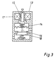
- FIG. 3 shows a gas valve (13) with an electromagnetically variable pressure regulator.
- the pressure regulator membrane (14) instead of the usual screw with a electrically actuated solenoid (15) is formed, which is movable in two positions.
- the solenoid (15) and its position are used to determine the corresponding position Nozzle pre-pressure generated, so that only one nozzle for natural gas or LPG is required.
- the solenoid (15) has one spring-biased piston (16) formed within certain limits by a Electromagnets (17) with variable DC voltage or PWM signal is controlled. So are any position and thus any pressure can be set in a gas range.
- the pressure regulator which is coupled to a valve seat (18), closed.
- the gas pressure regulator is preferably behind the gas valve at the gas inlet and in front of the gas nozzle at the outlet arranged. It consists of the diaphragm (14) and movable on the piston rod (16) the control valve. The piston is pressed down by the electromagnet (17). Against that the spring acts under the valve (18) so that the valve (18) closes when the electromagnet (17) fails. Gas pressure fluctuations are caused by the spring that acts on the diaphragm (14) corrected.
- Figure 4 shows a gas-heated clothes dryer with a program selection and Control device (1), a device for regulating the heating operation (2) and one Device for supplying gas (3) to a burner (4).
- Burners (4) are means (5) for automatically adapting the gas supply to the existing one Gas type arranged.
- the gas supply is adjusted as in the examples in FIGS. 1 to 3 shown.
- a selector switch (6) located in the control panel Drying program selected for operating the device.
- Via another selector switch or a keyboard (7) is entered for the gas type so that the adaptation of the nozzles or appropriate setting of the nozzle pressure on the pressure regulator can be made automatically.
- the entry is only required for the first commissioning at the respective location of the device required.
- a change in the setting is usually only when the location of the Device required.
Landscapes
- Engineering & Computer Science (AREA)
- Chemical & Material Sciences (AREA)
- Combustion & Propulsion (AREA)
- Mechanical Engineering (AREA)
- General Engineering & Computer Science (AREA)
- Feeding And Controlling Fuel (AREA)
Applications Claiming Priority (2)
| Application Number | Priority Date | Filing Date | Title |
|---|---|---|---|
| DE19748570 | 1997-11-04 | ||
| DE19748570A DE19748570A1 (de) | 1997-11-04 | 1997-11-04 | Gasbeheiztes Gerät mit einer Einrichtung zur Regelung des Heizbetriebes |
Publications (2)
| Publication Number | Publication Date |
|---|---|
| EP0915295A2 true EP0915295A2 (fr) | 1999-05-12 |
| EP0915295A3 EP0915295A3 (fr) | 1999-09-29 |
Family
ID=7847500
Family Applications (1)
| Application Number | Title | Priority Date | Filing Date |
|---|---|---|---|
| EP98120836A Withdrawn EP0915295A3 (fr) | 1997-11-04 | 1998-11-03 | Appareil chauffé au gaz avec un dispositif pour commander le chauffage |
Country Status (2)
| Country | Link |
|---|---|
| EP (1) | EP0915295A3 (fr) |
| DE (1) | DE19748570A1 (fr) |
Cited By (12)
| Publication number | Priority date | Publication date | Assignee | Title |
|---|---|---|---|---|
| NL1015797C2 (nl) * | 2000-07-25 | 2002-01-28 | Nefit Buderus B V | Verbrandingsinrichting en werkwijze voor het besturen van een verbrandingsinrichting. |
| EP1382907A1 (fr) * | 2002-07-12 | 2004-01-21 | G. Kromschröder Aktiengesellschaft | Dispositif pour régler le débit de gaz dans un brûleur |
| WO2005073632A1 (fr) * | 2004-01-28 | 2005-08-11 | Sit La Precisa S.P.A. | Unite de soupape multifonction controlant la fourniture de gaz combustible a un bruleur |
| WO2010092155A1 (fr) | 2009-02-16 | 2010-08-19 | Basf Se | Nouveaux producteurs microbiens d'acide succinique et purification d'acide succinique |
| US20100304317A1 (en) * | 2006-12-22 | 2010-12-02 | David Deng | Control valves for heaters and fireplace devices |
| US8545216B2 (en) | 2006-12-22 | 2013-10-01 | Continental Appliances, Inc. | Valve assemblies for heating devices |
| US8764436B2 (en) | 2006-12-22 | 2014-07-01 | Procom Heating, Inc. | Valve assemblies for heating devices |
| US9441833B2 (en) | 2013-03-02 | 2016-09-13 | David Deng | Heating assembly |
| US9671111B2 (en) | 2013-03-13 | 2017-06-06 | Ghp Group, Inc. | Fuel selector valve with shutter mechanism for a gas burner unit |
| US9752779B2 (en) | 2013-03-02 | 2017-09-05 | David Deng | Heating assembly |
| US9829195B2 (en) | 2009-12-14 | 2017-11-28 | David Deng | Dual fuel heating source with nozzle |
| US10066838B2 (en) | 2006-05-30 | 2018-09-04 | David Deng | Dual fuel heating system |
Families Citing this family (7)
| Publication number | Priority date | Publication date | Assignee | Title |
|---|---|---|---|---|
| DE19853262A1 (de) * | 1998-11-18 | 2000-05-25 | Bsh Bosch Siemens Hausgeraete | Regelung der Brennerheizleistung bei einem gasbetriebenen Koch- oder Backgerät |
| DE19937137C2 (de) * | 1999-08-06 | 2002-10-10 | Andreas Nordhoff | Verfahren und Vorrichtung zur kombinierten Lüftung und Heizung |
| DE10017990C2 (de) * | 2000-04-11 | 2002-03-07 | Viessmann Werke Kg | Gasgebläsebrenner |
| DE10022882B4 (de) * | 2000-05-10 | 2010-04-29 | Loi Thermprocess Gmbh | Verfahren und Vorrichtung zum Regeln eines Brenners |
| DE10322217B4 (de) * | 2003-05-16 | 2005-03-10 | Miele & Cie | Einstelleinrichtung für ein Gaskochgerät und Gaskochgerät |
| DE102010036100A1 (de) * | 2010-08-13 | 2012-02-16 | Ebm-Papst Landshut Gmbh | Mischvorrichtung zur Mischung von Verbrennungsluft und Gas sowie Feuerungseinrichtung |
| EP2444730A1 (fr) | 2010-10-19 | 2012-04-25 | Coprecitec, S.L. | Méthode de montage d'un robinet de gaz électromagnétiques, et vanne de gaz électromagnétique |
Citations (2)
| Publication number | Priority date | Publication date | Assignee | Title |
|---|---|---|---|---|
| DE4230201A1 (de) | 1991-09-09 | 1993-03-11 | Vaillant Joh Gmbh & Co | Servodruckregler |
| DE4326945C2 (de) | 1993-08-11 | 1996-10-24 | Schott Glaswerke | Regeleinrichtung für die Gaszufuhr zu einer Gaskocheinrichtung mit unter einer durchgehenden Kochfläche angeordneten Gasstrahlungsbrennern |
Family Cites Families (6)
| Publication number | Priority date | Publication date | Assignee | Title |
|---|---|---|---|---|
| DE1944847A1 (de) * | 1969-09-04 | 1970-10-08 | Kueppersbusch | Atmosphaerischer Mehrfachflammen-Allgasbrenner |
| JPS599425A (ja) * | 1982-07-07 | 1984-01-18 | Matsushita Electric Ind Co Ltd | 燃焼ガス供給装置 |
| FR2623880B1 (fr) * | 1987-11-27 | 1990-04-27 | Sdecc | Mecanisme d'alimentation modulable du gaz au bruleur d'un appareil du genre chaudiere a gaz |
| JPH0293206A (ja) * | 1988-09-29 | 1990-04-04 | Toshiba Corp | 燃焼装置 |
| US5238398A (en) * | 1991-06-17 | 1993-08-24 | Harmony Thermal Company, Inc. | Variable orifice gas modulating valve |
| DE69320514T2 (de) * | 1992-03-26 | 1999-04-29 | Matsushita Electric Industrial Co., Ltd., Kadoma, Osaka | Gasgerät |
-
1997
- 1997-11-04 DE DE19748570A patent/DE19748570A1/de not_active Withdrawn
-
1998
- 1998-11-03 EP EP98120836A patent/EP0915295A3/fr not_active Withdrawn
Patent Citations (2)
| Publication number | Priority date | Publication date | Assignee | Title |
|---|---|---|---|---|
| DE4230201A1 (de) | 1991-09-09 | 1993-03-11 | Vaillant Joh Gmbh & Co | Servodruckregler |
| DE4326945C2 (de) | 1993-08-11 | 1996-10-24 | Schott Glaswerke | Regeleinrichtung für die Gaszufuhr zu einer Gaskocheinrichtung mit unter einer durchgehenden Kochfläche angeordneten Gasstrahlungsbrennern |
Cited By (15)
| Publication number | Priority date | Publication date | Assignee | Title |
|---|---|---|---|---|
| NL1015797C2 (nl) * | 2000-07-25 | 2002-01-28 | Nefit Buderus B V | Verbrandingsinrichting en werkwijze voor het besturen van een verbrandingsinrichting. |
| EP1176364A1 (fr) * | 2000-07-25 | 2002-01-30 | Nefit Buderus B.V. | Dispositif de combustion et procédé de commande d'un dispositif de combustion |
| EP1382907A1 (fr) * | 2002-07-12 | 2004-01-21 | G. Kromschröder Aktiengesellschaft | Dispositif pour régler le débit de gaz dans un brûleur |
| WO2005073632A1 (fr) * | 2004-01-28 | 2005-08-11 | Sit La Precisa S.P.A. | Unite de soupape multifonction controlant la fourniture de gaz combustible a un bruleur |
| US10066838B2 (en) | 2006-05-30 | 2018-09-04 | David Deng | Dual fuel heating system |
| US8317511B2 (en) * | 2006-12-22 | 2012-11-27 | Continental Appliances, Inc. | Control valves for heaters and fireplace devices |
| US20100304317A1 (en) * | 2006-12-22 | 2010-12-02 | David Deng | Control valves for heaters and fireplace devices |
| US8545216B2 (en) | 2006-12-22 | 2013-10-01 | Continental Appliances, Inc. | Valve assemblies for heating devices |
| US8764436B2 (en) | 2006-12-22 | 2014-07-01 | Procom Heating, Inc. | Valve assemblies for heating devices |
| US9328922B2 (en) | 2006-12-22 | 2016-05-03 | Procom Heating, Inc. | Valve assemblies for heating devices |
| WO2010092155A1 (fr) | 2009-02-16 | 2010-08-19 | Basf Se | Nouveaux producteurs microbiens d'acide succinique et purification d'acide succinique |
| US9829195B2 (en) | 2009-12-14 | 2017-11-28 | David Deng | Dual fuel heating source with nozzle |
| US9441833B2 (en) | 2013-03-02 | 2016-09-13 | David Deng | Heating assembly |
| US9752779B2 (en) | 2013-03-02 | 2017-09-05 | David Deng | Heating assembly |
| US9671111B2 (en) | 2013-03-13 | 2017-06-06 | Ghp Group, Inc. | Fuel selector valve with shutter mechanism for a gas burner unit |
Also Published As
| Publication number | Publication date |
|---|---|
| DE19748570A1 (de) | 1999-05-06 |
| EP0915295A3 (fr) | 1999-09-29 |
Similar Documents
| Publication | Publication Date | Title |
|---|---|---|
| DE19748570A1 (de) | Gasbeheiztes Gerät mit einer Einrichtung zur Regelung des Heizbetriebes | |
| EP1671066B2 (fr) | Fourneau gaz | |
| EP0863339B1 (fr) | Régulateur de gaz | |
| DE4206875A1 (de) | Gasdruckregelsystem | |
| EP2756229B1 (fr) | Ensemble de soupapes à gaz | |
| DE68910277T2 (de) | Modulierter Gas-Radiator. | |
| EP0836054A1 (fr) | Procédé et dispositif de commande de la grandeur de la flamme des appareils de cuisson à gaz | |
| EP0532453B1 (fr) | Régulateur de pression de gaz | |
| DE2906044C2 (de) | Gasdruckregler für eine gasbeheizte Wärmequelle | |
| DE1751798A1 (de) | Stroemungsmittelsteuereinrichtung,insbesondere fuer einen Haupt- und einen Zuendbrenner aufweisende,geregelte Brennmittelkammer | |
| DE2509893A1 (de) | Vorrichtung zum steuern und regeln des druckes eines stroemenden heizgases | |
| DE19601517A1 (de) | Regelung eines Gasheizgeräts | |
| DE102009012290A1 (de) | Gasventilmodul | |
| DE2742755C2 (de) | Magnetventil | |
| DE3941879C1 (fr) | ||
| DE2362905A1 (de) | Regelventil | |
| DE3524015C2 (fr) | ||
| EP0940493A1 (fr) | Sèche-linge chauffé au gaz | |
| EP4660543A1 (fr) | Dispositif de chauffage de locaux et procédé de fonctionnement d'un dispositif de chauffage de locaux | |
| EP1241410B1 (fr) | Dispositif d'alimentation en gaz pour un chauffe-eau à gaz | |
| DE9101263U1 (de) | Gasdruckregler | |
| DE202023002780U1 (de) | Raumheizungseinrichtung | |
| DE69917300T2 (de) | Steuerungsvorrichtung zur Einstellung eines Aktuators | |
| WO1989009367A1 (fr) | Chauffe-eau instantane chauffe au gaz | |
| DE202005000346U1 (de) | Druckgesteuertes Doppelabsperrventil |
Legal Events
| Date | Code | Title | Description |
|---|---|---|---|
| PUAI | Public reference made under article 153(3) epc to a published international application that has entered the european phase |
Free format text: ORIGINAL CODE: 0009012 |
|
| AK | Designated contracting states |
Kind code of ref document: A2 Designated state(s): AT BE CH CY DE DK ES FI FR GB GR IE IT LI LU MC NL PT SE |
|
| AX | Request for extension of the european patent |
Free format text: AL;LT;LV;MK;RO;SI |
|
| PUAL | Search report despatched |
Free format text: ORIGINAL CODE: 0009013 |
|
| AK | Designated contracting states |
Kind code of ref document: A3 Designated state(s): AT BE CH CY DE DK ES FI FR GB GR IE IT LI LU MC NL PT SE |
|
| AX | Request for extension of the european patent |
Free format text: AL;LT;LV;MK;RO;SI |
|
| AKX | Designation fees paid | ||
| REG | Reference to a national code |
Ref country code: DE Ref legal event code: 8566 |
|
| STAA | Information on the status of an ep patent application or granted ep patent |
Free format text: STATUS: THE APPLICATION IS DEEMED TO BE WITHDRAWN |
|
| 18D | Application deemed to be withdrawn |
Effective date: 20000330 |