EP0915324A2 - Débimètre magnétique - Google Patents
Débimètre magnétique Download PDFInfo
- Publication number
- EP0915324A2 EP0915324A2 EP98309028A EP98309028A EP0915324A2 EP 0915324 A2 EP0915324 A2 EP 0915324A2 EP 98309028 A EP98309028 A EP 98309028A EP 98309028 A EP98309028 A EP 98309028A EP 0915324 A2 EP0915324 A2 EP 0915324A2
- Authority
- EP
- European Patent Office
- Prior art keywords
- circuit
- output
- electrode
- fluid
- electrodes
- Prior art date
- Legal status (The legal status is an assumption and is not a legal conclusion. Google has not performed a legal analysis and makes no representation as to the accuracy of the status listed.)
- Granted
Links
Images


Classifications
-
- G—PHYSICS
- G01—MEASURING; TESTING
- G01F—MEASURING VOLUME, VOLUME FLOW, MASS FLOW OR LIQUID LEVEL; METERING BY VOLUME
- G01F1/00—Measuring the volume flow or mass flow of fluid or fluent solid material wherein the fluid passes through a meter in a continuous flow
- G01F1/002—Measuring the volume flow or mass flow of fluid or fluent solid material wherein the fluid passes through a meter in a continuous flow wherein the flow is in an open channel
-
- G—PHYSICS
- G01—MEASURING; TESTING
- G01F—MEASURING VOLUME, VOLUME FLOW, MASS FLOW OR LIQUID LEVEL; METERING BY VOLUME
- G01F1/00—Measuring the volume flow or mass flow of fluid or fluent solid material wherein the fluid passes through a meter in a continuous flow
- G01F1/56—Measuring the volume flow or mass flow of fluid or fluent solid material wherein the fluid passes through a meter in a continuous flow by using electric or magnetic effects
- G01F1/58—Measuring the volume flow or mass flow of fluid or fluent solid material wherein the fluid passes through a meter in a continuous flow by using electric or magnetic effects by electromagnetic flowmeters
- G01F1/60—Circuits therefor
-
- G—PHYSICS
- G01—MEASURING; TESTING
- G01F—MEASURING VOLUME, VOLUME FLOW, MASS FLOW OR LIQUID LEVEL; METERING BY VOLUME
- G01F25/00—Testing or calibration of apparatus for measuring volume, volume flow or liquid level or for metering by volume
- G01F25/10—Testing or calibration of apparatus for measuring volume, volume flow or liquid level or for metering by volume of flowmeters
Definitions
- Magnetic flowmeters measure the rate of flow of a process fluid through a tube.
- Magnetic coils mounted on opposite sides of the tube produce a magnetic field perpendicular to the direction of fluid flow in the tube.
- Electrodes placed in the tube measure a resulting voltage in the fluid that is perpendicular to both the direction of fluid flow and the magnetic field.
- a processor converts the output of the electrodes to a measure of the rate of fluid flow.
- Some magnetic flowmeters are equipped with a circuit that detects the presence of fluid in the tube and prevents the flowmeter from measuring a non-zero flow rate when the tube is empty.
- One such circuit manufactured by Fischer and Porter, produces an oscillating signal to indicate that the tube is full. The oscillating signal disappears when the tube is empty.
- the electrodes in a flowmeter can become fouled. Such fouling can adversely affect the signal monitored at the electrodes.
- Electrode fouling in general, increases the impedance between a flowmeter electrode and the fluid ground tied to the flowmeter tube due to a build up of an insulating coating on the electrode. As an empty tube also results in an increase in impedance between the electrode and the fluid ground, an erroneous empty tube signal can result if an electrode becomes sufficiently fouled.
- a flowmeter may be configured such that when an empty tube signal is detected, that is, a high impedance is detected between the electrode and the fluid ground, the flow signal output from the flowmeter may be locked to prevent the output of an erroneous flow rate, due, for example, to signal drift. Therefore, an erroneous empty tube signal due to electrode fouling may result in improper locking of the flow signal.
- the invention provides a magnetic flowmeter with a diagnostic circuit that outputs a signal indicating fouling of an electrode of the flowmeter.
- the flowmeter has a tube for supporting fluid flow and includes a diagnostic circuit for indicating when an electrode in the flowmeter is partially fouled.
- the invention can include one or more of the following features.
- a diagnostic circuit in the flowmeter can detect partial fouling before an erroneous empty tube signal is generated.
- the same circuit arrangement used to detect an empty tube can be used to provide a diagnostic signal indicating the partial fouling of the electrode.
- the diagnostic circuit can warn an operator who can respond, for example, by recalibrating the circuit to account for the fouling or by cleaning the electrodes using mechanical or chemical methods.
- the diagnostic circuit can be repeatedly enabled, for example periodically. When the diagnostic circuit is enabled, and the electrode is partially fouled, the diagnostic circuit can output a substantially oscillating signal.
- the flowmeter can include a circuit for indicating when the tube is empty, for example by detecting a high impedance between the electrode and the fluid ground.
- the diagnostic circuit and the empty tube detection circuit can include a digitally controlled variable resistance, controlled with a diagnostic control value and an empty tube detection control value respectively.
- the diagnostic circuit can be enabled by controlling the variable resistance with the diagnostic control value.
- a circuit for processing the output of an electrode in a fluid-supporting tube of a magnetic flowmeter including a device receiving an output of the electrode, and being characterised in that a diagnostic subcircuit is connected to the device, the diagnostic subcircuit being adapted to cause an output signal of the device to oscillate if the electrode is partially fouled.
- the invention provides a method for detecting when an electrode immersed in a fluid has partially fouled, comprising: measuring an output of the electrode normally immersed in fluid; providing the output to a circuit; configuring the circuit so that the circuit provides an non-oscillating output when the electrode is not fouled; and providing an indication that the electrode has partially fouled based on an oscillating output of the circuit.
- the invention provides, in a fourth alternative aspect thereof, a method for detecting a high impedance between two electrodes normally immersed in a fluid and a fluid ground, the method comprising: measuring an output of the two electrodes; providing the output to a circuit; configuring the circuit so that the circuit provides an oscillating output when a high impedance is present between the electrodes and the fluid ground; providing an indication that the electrodes are not immersed based on the oscillating output, periodically determining whether the electrodes have partially fouled, including configuring the circuit so that the circuit provides a non-oscillating output if the electrodes are immersed and have not fouled and provides an oscillating output if the electrodes are immersed and have partially fouled.
- a method for measuring a resistance between an electrode normally immersed in a fluid and a fluid ground comprising: providing an output of the electrode to a circuit; configuring the circuit such that the output oscillates if the resistance is greater than a predetermined value.
- An erroneous empty tube signal due to an electrode fouling can be avoided by periodically enabling the diagnostic circuit to detect the onset of electrode fouling. If electrode fouling is detected, for example, to a degree which will begin to cause erroneous empty tube signals, the flowmeter and diagnostic circuit can be recalibrated to account for the level of fouling.
- the calibration mode can be used in a troubleshooting situation in order to determine the impedance between an electrode and a fluid ground.
- the approach avoids difficulties that may be encountered using other impedance measuring techniques, such as using a direct current based ohm-meter.
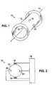
- Fig. 1 is a schematic perspective view of a magnetic flowmeter.
- Fig. 2 is a schematic front view of the flowmeter of Fig. 1.
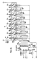
- Figs. 3a and 3b are circuit diagrams of an empty tube detection circuit in the flowmeter of Figs. 1 and 2.
- Fig. 4 is a flowchart for a calibration procedure for the flowmeter of Figs 1 and 2.
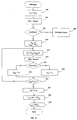
- Fig. 5 is a flowchart of a periodic diagnostic procedure.
- Fig. 6 is a flowchart of an alternative calibration procedure.
- a magnetic flowmeter 10 has a tube 12 for supporting fluid flow along its longitudinal axis 14.
- a pair of magnetic coils 16, 18 mounted on opposite sides of the tube create a magnetic field perpendicular to the axis of the tube.
- Electrodes 20, 22 are disposed on opposite sides of the interior of the tube, along a line perpendicular to axis 14 and the magnetic field. A surface of each electrode is in contact with the process fluid when the tube is full.
- Magnetic coils 16, 18 and electrodes 20, 22 are each connected to a processor 24 that controls the current through the coils and converts the output of the electrodes to a flow rate measurement, as well as performing other functions.
- processor 24 includes an empty tube detection circuit 50 connected to each electrode 20, 22.
- the resistance (2R) between each electrode and the fluid ground and between the electrodes depends on the conductivity of the process fluid, the size and placement of the electrodes, and the level of impurities on the inside of the tube.
- the preferred embodiment of circuit 50 described below is designed for process fluid conductivities ranging from at least 1.5 ⁇ /cm.
- Each electrode is connected to a non-inverting input 52 of an operational amplifier 53 via a variable resistance positive feedback path 54.
- the amplifier also has a fixed resistance negative feedback path 55.
- the resistance (2R) between the electrodes and the tube is high, and the positive feedback to the amplifier exceeds the negative feedback and the output of the amplifier oscillates.
- the negative feedback exceeds the positive feedback to the amplifier and the output no longer oscillates. The presence of an oscillating output thus signals to the processor that the tube is empty.
- the negative feedback path includes a 10 kOhm resistor 66 connecting an inverting input 64 of the amplifier to ground.
- the output of the amplifier is fed back to the inverting input of the amplifier via a 191 kOhm resistor 68.
- the amplifier is biased by a bipolar supply voltage in a conventional manner.
- the positive feedback path includes 2200 pF capacitors 56, 58 connecting each electrode to the non-inverting input of the amplifier.
- the capacitors prevent DC signals from coupling to the electrodes, which could interfere with the flow measurement signal from the electrode.
- the electrodes act essentially as AC voltage sources with a source resistance, and the magnitude of the coil current and the presence or absence of fluid flow in the tube do not disturb the empty tube measurement.
- the outputs of the capacitors are additionally connected to a 1 MOhm resistor 60 to provide a path for the bias current of the non-inverting input.
- Subcircuit 70 couples the output of the amplifier to ground via a 9.09 kOhm resistor 72 connected in series to a 1 kOhm resistor 74. These resistors attenuate the output of the amplifier to prevent a large signal from being coupled back to the electrodes.
- resistor 72 The output of resistor 72 is coupled to the non-inverting input of the amplifier by a variable resistor 76, with resistance R s , connected in series with a 4700 pF capacitor 78.
- Capacitor 78 compensates for the capacitive reactance of parallel capacitors 56, 58. The amplifier is thus stable at DC when the negative feedback exceeds the positive feedback.
- Variable resistor 76 includes eight resistors 80 1 ,...,80 8 connected in series and having varying resistances.
- resistors 80 1 to 80 8 have values of .590, 1.40, 3.32, 7.87, 18.7, 44, 105 and 249 kOhm, respectively.
- Each resistor 80 1 ,...,80 8 is connected in parallel to a switch 82 1 ,...,82 8 coupled to an output of a shift register 84.
- Shift register 84 receives digital signals from the processor, and varies the resistance of resistor 76 by selectively opening or closing the switches.
- Shift register 84 outputs eight binary signals which taken as an 8-bit unsigned number is a control value C s which is approximately linearly related to the resulting variable resistance R s .
- the minimum resistance of the variable resistor is lower than the resistance (R min ) at which the circuit will oscillate when the tube is full.
- the maximum resistance of the variable resistor exceeds the highest resistance (R max ) at which the circuit will not oscillate when empty.
- the output of amplifier 53 is also connected to a rectifier 86 which provides a DC signal 88 to a CMOS inverter.
- the inverter provides a digital signal to the processor indicating whether the tube is full or empty.
- the rectifier includes a diode 90 connected in series to a 10 ⁇ F capacitor 92, 10 ⁇ F capacitor 94 and a 1 MOhm resistor 96, all connected in parallel.
- the processor causes the magnetic coils 16, 18 to produce an alternating magnetic field in the tube 12 (Fig. 1). This causes electrodes 20, 22 to supply an AC signal to amplifier 53. Above a threshold resistance established by variable resistor 76, the positive feedback exceeds the negative feedback, thus the amplifier produces an oscillating output. When the positive feedback is less than the negative feedback, the output of the amplifier is a low voltage DC signal.
- a technician calibrates the flowmeter circuitry using the method shown in Fig. 4.
- the technician instructs the processor to set the variable resistance to a low value (e.g., the minimum value of 250 Ohms) (step 200).
- a low value e.g., the minimum value of 250 Ohms
- the oscillating output of the amplifier is converted to a high DC signal by the rectifier, and the inverter converts this signal to a digital logic High signal indicating to the processor that the tube is empty. This triggers the processor to interrupt the flow measurement, and indicate to the user that the tube is empty.
- the technician then gradually increases the variable resistance until the positive feedback no longer exceeds the negative feedback input to the amplifier, and the output of the amplifier stops oscillating (step 202).
- the DC signal at the output of the rectifier is now a low signal, which the inverter converts to a logic Low signal indicating that the tube is full.
- the technician must set the variable resistance at a value below this threshold resistance (R max ) by setting the control values below to corresponding control value C max .
- the technician fills the tube with a particular process fluid, e.g., by connecting the tube to a pipeline (step 204). This causes the resistance between the electrodes and the tube to decrease (in relation to the conductivity of the fluid) and prevents the output of the amplifier from oscillating.
- the technician then continues his calibration by decreasing the variable resistance until the positive feedback to the amplifier exceeds the negative feedback, and the circuit resumes oscillating (step 206).
- the variable resistance (R s ) must be set to a value (R sp ) that exceeds this threshold resistance (R min ) but remains below R max (step 208).
- the control value corresponding to variable resistance R min is C min .
- the technician then repeats steps 200 through 208 for another process fluid, having another fluid conductivity. He then either stores in the processor appropriate values of R SP for each fluid, or he derives an equation relating R SP to R min and stores this equation, in terms of variable resistor control values C SP and C min , in the processor.
- R SP 64+1.5C min
- Conductivities that vary greatly from those given above may require a different formula or a variable resistor with a different range of resistances to be employed. It is sufficient to derive R SP based only on R min since R max is related to R min .
- An end user then chooses a flowmeter, calibrated according to the process described above, that is appropriate for the particular process fluid the user wishes to measure.
- the user then sets up the flowmeter by indicating to the processor the type of fluid to be measured. If a lookup table is used, the processor matches the fluid type to its corresponding resistance R S stored in memory, and sets the variable resistance to that value.
- the processor stores an equation in the form of Equation (1)
- the user first ensures that the tube is full before activating the processor for calibration.
- the processor turns all switches off so that the variable resistor is at a maximum value. Because this resistance exceeds R min , the amplifier does not oscillate and the processor indicates a full tube.
- the processor then gradually decreases the variable resistance until the amplifier oscillates and an empty tube signal is generated. The value of the resistance that causes the empty tube signal is set to R min .
- the processor then calculates R S from R min based on Equation (1).
- the user re-activates the calibration procedure whenever the type of process fluid changes, or when an insulating coating builds up on the electrodes during fouling.
- the processor automatically re-calibrates the circuit at set intervals.
- a diagnostic message is sent alerting the operator that an electrode fouling condition may exist. Specifically, a warning counter is incremented if the circuit oscillates (step 508) and reset to zero if it does not (step 510). If the warning counter reaches 3, (step 512) then a diagnostic warning message is issued (step 514).
- a warning counter is incremented if the circuit oscillates (step 508) and reset to zero if it does not (step 510). If the warning counter reaches 3, (step 512) then a diagnostic warning message is issued (step 514).
- An alternative automatic calibration mode can be used to determine R min , the setting of the variable resistance below which the outputs oscillate when the tube is full. Rather than gradually decreasing R S until oscillation is achieved, a binary search can be used as shown in Fig. 6.
- the control value C S for variable resistor 76 is set to 127 10 (step 602). After waiting for 1 second (step 604) the signal at electrodes 20,22 is tested for oscillation (step 606). If the signal is oscillating, calibration fails (step 608) since the oscillation indicates, for example, that the electrode resistance or the fluid resistivity are unexpectedly high. If the signal does not oscillate at this initial control value, a binary search is performed to find the minimum control value C S such that the signal does not oscillate.
- a control value is chosen at the midpoint of the current range (step 612) and then the system waits for 1 second (step 614).
- Oscillation of the electrode signal is tested (step 616) and either the C low is increased to C S (step 620) in the case of oscillation, or C high is reduced to C S if there is no oscillation (step 618). If a range of control values remains between C low and C high (step 622) the cycle is repeated, otherwise C min is set to C high (step 624), the lowest control value that does not result in oscillation.
- the control value C SP is set according to equation 1 (step 626) and the electrode fouling warning level C WARN is set to 0.8C SP (step 628).
- an automatic calibration mode of the types described above and shown in Fig. 6 can be used to determine the impedance from between an electrode and a fluid ground in a trouble-shooting mode.
- the calibration is controlled by an operator trouble-shooting a flowmeter or other equipment including an electrode immersed in a fluid.
- the variable resistance R S of variable resistor 76 is varied in a sequence, in particular the sequence corresponding to the binary search shown in Fig. 6. For any value of R s in the sequence, there is a corresponding resistance R between each of the electrodes and the fluid ground above which the positive feedback to the operation amplifier exceeds the negative feedback, than therefore the output of the amplifier oscillates.
- the calibration procedure fails (step 608) then there may be an open circuit due, for example, to a broken wire, a faulty tube to fluid ground connection, a fouled electrode, or a non-conductive fluid. If the calibration procedure succeeds then an open circuit can be ruled out and a value of R can determined from C min . In particular, at the end of a successful calibration, the value of R can be bounded based on the greatest value of R S for which the circuit oscillated and lowest value of R s for which it did not.
- inventions can use any of a number of methods of varying the circuit characteristics to enable a diagnostic mode.
- other types of controlled variable resistances can be used, including multiplying digital-to-analog converters and analog multipliers.
- Any of a number of circuits for supplying a digital control signal can be used rather than the shift register (serial-to-parallel converter) in the above embodiments.
- values of various components in circuit 50 are varied to accommodate process fluids with different conductivities.
- values of capacitors 56, 58, 78 are decreased to 1500 pF to create a circuit less sensitive to low frequencies.
- the capacitance of the capacitors exceeds 200 pF to increase the sensitivity of the amplifier.
- the output of the amplifier can be attenuated by decreasing the supply voltages to the amplifier or limiting the amplifier's output swing with zener diodes.
- Temperature correction circuits can be connected to the circuit to compensate for fluctuations in the temperature of the process fluid.
Landscapes
- Physics & Mathematics (AREA)
- Fluid Mechanics (AREA)
- General Physics & Mathematics (AREA)
- Electromagnetism (AREA)
- Measuring Volume Flow (AREA)
Applications Claiming Priority (2)
| Application Number | Priority Date | Filing Date | Title |
|---|---|---|---|
| US964303 | 1997-11-04 | ||
| US08/964,303 US6014902A (en) | 1995-12-28 | 1997-11-04 | Magnetic flowmeter with diagnostics |
Publications (3)
| Publication Number | Publication Date |
|---|---|
| EP0915324A2 true EP0915324A2 (fr) | 1999-05-12 |
| EP0915324A3 EP0915324A3 (fr) | 1999-06-30 |
| EP0915324B1 EP0915324B1 (fr) | 2012-02-08 |
Family
ID=25508380
Family Applications (1)
| Application Number | Title | Priority Date | Filing Date |
|---|---|---|---|
| EP98309028A Expired - Lifetime EP0915324B1 (fr) | 1997-11-04 | 1998-11-04 | Débimètre magnétique |
Country Status (4)
| Country | Link |
|---|---|
| US (1) | US6014902A (fr) |
| EP (1) | EP0915324B1 (fr) |
| CA (1) | CA2252257A1 (fr) |
| FI (1) | FI982381A7 (fr) |
Cited By (6)
| Publication number | Priority date | Publication date | Assignee | Title |
|---|---|---|---|---|
| GB2348012A (en) * | 1996-01-17 | 2000-09-20 | Abb Instrumentation Ltd | Testing and calibration of electromagnetic flowmeters |
| WO2001090701A3 (fr) * | 2000-05-25 | 2002-05-16 | Rosemount Inc | Indication de conduction de liquide dans un debimetre electromagnetique |
| US6453272B1 (en) | 2000-02-28 | 2002-09-17 | The Foxboro Company | Spurious noise filter |
| US6697742B1 (en) | 1996-01-17 | 2004-02-24 | Abb Kent-Taylor Limited | Method and apparatus for testing electromagnetic flowmeters |
| DE102007014469A1 (de) * | 2007-03-22 | 2008-09-25 | Endress + Hauser Flowtec Ag | Verfahren zur vorausschauenden Wartung und/oder Verfahren zur Bestimmung der elektrischen Leitfähigkeit bei einem magnetischinduktiven Durchflussmessgerät |
| DE10243748B4 (de) * | 2001-09-20 | 2018-11-08 | Yokogawa Electric Corporation | Elektromagnetischer Durchflussmesser |
Families Citing this family (42)
| Publication number | Priority date | Publication date | Assignee | Title |
|---|---|---|---|---|
| US8290721B2 (en) * | 1996-03-28 | 2012-10-16 | Rosemount Inc. | Flow measurement diagnostics |
| US7630861B2 (en) * | 1996-03-28 | 2009-12-08 | Rosemount Inc. | Dedicated process diagnostic device |
| US6017143A (en) | 1996-03-28 | 2000-01-25 | Rosemount Inc. | Device in a process system for detecting events |
| US7949495B2 (en) * | 1996-03-28 | 2011-05-24 | Rosemount, Inc. | Process variable transmitter with diagnostics |
| US7623932B2 (en) | 1996-03-28 | 2009-11-24 | Fisher-Rosemount Systems, Inc. | Rule set for root cause diagnostics |
| US7085610B2 (en) | 1996-03-28 | 2006-08-01 | Fisher-Rosemount Systems, Inc. | Root cause diagnostics |
| US6654697B1 (en) | 1996-03-28 | 2003-11-25 | Rosemount Inc. | Flow measurement with diagnostics |
| US6539267B1 (en) | 1996-03-28 | 2003-03-25 | Rosemount Inc. | Device in a process system for determining statistical parameter |
| US6907383B2 (en) | 1996-03-28 | 2005-06-14 | Rosemount Inc. | Flow diagnostic system |
| US7254518B2 (en) | 1996-03-28 | 2007-08-07 | Rosemount Inc. | Pressure transmitter with diagnostics |
| US6754601B1 (en) | 1996-11-07 | 2004-06-22 | Rosemount Inc. | Diagnostics for resistive elements of process devices |
| US6601005B1 (en) | 1996-11-07 | 2003-07-29 | Rosemount Inc. | Process device diagnostics using process variable sensor signal |
| US6519546B1 (en) | 1996-11-07 | 2003-02-11 | Rosemount Inc. | Auto correcting temperature transmitter with resistance based sensor |
| US6615149B1 (en) | 1998-12-10 | 2003-09-02 | Rosemount Inc. | Spectral diagnostics in a magnetic flow meter |
| US6611775B1 (en) * | 1998-12-10 | 2003-08-26 | Rosemount Inc. | Electrode leakage diagnostics in a magnetic flow meter |
| US7010459B2 (en) * | 1999-06-25 | 2006-03-07 | Rosemount Inc. | Process device diagnostics using process variable sensor signal |
| US6505517B1 (en) | 1999-07-23 | 2003-01-14 | Rosemount Inc. | High accuracy signal processing for magnetic flowmeter |
| US6701274B1 (en) | 1999-08-27 | 2004-03-02 | Rosemount Inc. | Prediction of error magnitude in a pressure transmitter |
| US6556145B1 (en) | 1999-09-24 | 2003-04-29 | Rosemount Inc. | Two-wire fluid temperature transmitter with thermocouple diagnostics |
| US6970003B2 (en) | 2001-03-05 | 2005-11-29 | Rosemount Inc. | Electronics board life prediction of microprocessor-based transmitters |
| US6629059B2 (en) | 2001-05-14 | 2003-09-30 | Fisher-Rosemount Systems, Inc. | Hand held diagnostic and communication device with automatic bus detection |
| US6772036B2 (en) | 2001-08-30 | 2004-08-03 | Fisher-Rosemount Systems, Inc. | Control system using process model |
| RU2324171C2 (ru) * | 2003-07-18 | 2008-05-10 | Роузмаунт Инк. | Диагностика процесса |
| DE10335205A1 (de) * | 2003-07-30 | 2005-02-17 | Endress + Hauser Flowtec Ag, Reinach | Verfahren zur magnetisch-induktiven Bestimmung der Durchflußrate eines Mediums |
| US7018800B2 (en) * | 2003-08-07 | 2006-03-28 | Rosemount Inc. | Process device with quiescent current diagnostics |
| US7627441B2 (en) * | 2003-09-30 | 2009-12-01 | Rosemount Inc. | Process device with vibration based diagnostics |
| US7523667B2 (en) * | 2003-12-23 | 2009-04-28 | Rosemount Inc. | Diagnostics of impulse piping in an industrial process |
| US6920799B1 (en) | 2004-04-15 | 2005-07-26 | Rosemount Inc. | Magnetic flow meter with reference electrode |
| US7046180B2 (en) | 2004-04-21 | 2006-05-16 | Rosemount Inc. | Analog-to-digital converter with range error detection |
| US8112565B2 (en) * | 2005-06-08 | 2012-02-07 | Fisher-Rosemount Systems, Inc. | Multi-protocol field device interface with automatic bus detection |
| US20070068225A1 (en) * | 2005-09-29 | 2007-03-29 | Brown Gregory C | Leak detector for process valve |
| US7579947B2 (en) * | 2005-10-19 | 2009-08-25 | Rosemount Inc. | Industrial process sensor with sensor coating detection |
| US7953501B2 (en) | 2006-09-25 | 2011-05-31 | Fisher-Rosemount Systems, Inc. | Industrial process control loop monitor |
| JP2010505121A (ja) | 2006-09-29 | 2010-02-18 | ローズマウント インコーポレイテッド | 検証を備える磁気流量計 |
| US7321846B1 (en) | 2006-10-05 | 2008-01-22 | Rosemount Inc. | Two-wire process control loop diagnostics |
| US8898036B2 (en) * | 2007-08-06 | 2014-11-25 | Rosemount Inc. | Process variable transmitter with acceleration sensor |
| US7590511B2 (en) * | 2007-09-25 | 2009-09-15 | Rosemount Inc. | Field device for digital process control loop diagnostics |
| US7921734B2 (en) * | 2009-05-12 | 2011-04-12 | Rosemount Inc. | System to detect poor process ground connections |
| US9207670B2 (en) | 2011-03-21 | 2015-12-08 | Rosemount Inc. | Degrading sensor detection implemented within a transmitter |
| US9052240B2 (en) | 2012-06-29 | 2015-06-09 | Rosemount Inc. | Industrial process temperature transmitter with sensor stress diagnostics |
| US9602122B2 (en) | 2012-09-28 | 2017-03-21 | Rosemount Inc. | Process variable measurement noise diagnostic |
| US9696188B2 (en) | 2013-03-14 | 2017-07-04 | Rosemount Inc. | Magnetic flowmeter with automatic adjustment based on sensed complex impedance |
Citations (1)
| Publication number | Priority date | Publication date | Assignee | Title |
|---|---|---|---|---|
| US5370000A (en) | 1991-07-04 | 1994-12-06 | Fischer & Porter Company | Magnetic flowmeter with fault detection |
Family Cites Families (10)
| Publication number | Priority date | Publication date | Assignee | Title |
|---|---|---|---|---|
| US3834232A (en) * | 1972-08-22 | 1974-09-10 | Sybron Corp | Electromagnetic flowmeter having self-cleaning electrodes |
| US3991612A (en) * | 1975-10-14 | 1976-11-16 | Fischer & Porter Co. | Electromagnetic flowmeter usable in less-than full fluid lines |
| US4036052A (en) * | 1976-07-30 | 1977-07-19 | Fischer & Porter Co. | Electromagnetic flowmeter usable in less-than-full fluid lines |
| US4503711A (en) * | 1983-09-30 | 1985-03-12 | Rosemount Inc. | Travelling wave flowmeter |
| JPH01288724A (ja) * | 1988-05-17 | 1989-11-21 | Toshiba Corp | 電磁流量計の電極汚れ検知装置 |
| DE59008599D1 (de) * | 1990-04-09 | 1995-04-06 | Fischer & Porter Gmbh | Schaltungsanordnung zur Messung des Stroms einer elektrische Ladungen enthaltenden Flüssigkeit. |
| DE4127694A1 (de) * | 1991-08-21 | 1993-02-25 | Fischer & Porter Gmbh | Vorrichtung zur messung des stroms einer elektrische ladungen enthaltenden fluessigkeit |
| DK0535257T3 (da) * | 1991-09-10 | 1995-09-11 | Fischer & Porter Gmbh | Indretning til måling af strømningshastigheden af en væske, som strømmer med en fri overflade langs en ledning |
| US5426984A (en) * | 1993-09-02 | 1995-06-27 | Rosemount Inc. | Magnetic flowmeter with empty pipe detector |
| US5895864A (en) * | 1995-12-28 | 1999-04-20 | The Foxboro Company | Magnetic flowmeter with empty tube detection |
-
1997
- 1997-11-04 US US08/964,303 patent/US6014902A/en not_active Expired - Lifetime
-
1998
- 1998-10-29 CA CA002252257A patent/CA2252257A1/fr not_active Abandoned
- 1998-11-03 FI FI982381A patent/FI982381A7/fi unknown
- 1998-11-04 EP EP98309028A patent/EP0915324B1/fr not_active Expired - Lifetime
Patent Citations (1)
| Publication number | Priority date | Publication date | Assignee | Title |
|---|---|---|---|---|
| US5370000A (en) | 1991-07-04 | 1994-12-06 | Fischer & Porter Company | Magnetic flowmeter with fault detection |
Cited By (9)
| Publication number | Priority date | Publication date | Assignee | Title |
|---|---|---|---|---|
| GB2348012A (en) * | 1996-01-17 | 2000-09-20 | Abb Instrumentation Ltd | Testing and calibration of electromagnetic flowmeters |
| GB2348012B (en) * | 1996-01-17 | 2000-12-06 | Abb Instrumentation Ltd | Calibration of flow meters |
| US6697742B1 (en) | 1996-01-17 | 2004-02-24 | Abb Kent-Taylor Limited | Method and apparatus for testing electromagnetic flowmeters |
| US6611770B1 (en) | 1998-12-10 | 2003-08-26 | Rosemount Inc. | Liquid conduction indication in a magnetic flowmeter |
| US6453272B1 (en) | 2000-02-28 | 2002-09-17 | The Foxboro Company | Spurious noise filter |
| WO2001090701A3 (fr) * | 2000-05-25 | 2002-05-16 | Rosemount Inc | Indication de conduction de liquide dans un debimetre electromagnetique |
| DE10243748B4 (de) * | 2001-09-20 | 2018-11-08 | Yokogawa Electric Corporation | Elektromagnetischer Durchflussmesser |
| DE102007014469A1 (de) * | 2007-03-22 | 2008-09-25 | Endress + Hauser Flowtec Ag | Verfahren zur vorausschauenden Wartung und/oder Verfahren zur Bestimmung der elektrischen Leitfähigkeit bei einem magnetischinduktiven Durchflussmessgerät |
| US8046194B2 (en) | 2007-03-22 | 2011-10-25 | Endress + Hauser Flowtec Ag | Method for predictive maintenance and/or method for determining electrical conductivity in a magneto-inductive flow-measuring device |
Also Published As
| Publication number | Publication date |
|---|---|
| EP0915324A3 (fr) | 1999-06-30 |
| FI982381L (fi) | 1999-05-05 |
| FI982381A7 (fi) | 1999-05-05 |
| FI982381A0 (fi) | 1998-11-03 |
| EP0915324B1 (fr) | 2012-02-08 |
| CA2252257A1 (fr) | 1999-05-04 |
| US6014902A (en) | 2000-01-18 |
Similar Documents
| Publication | Publication Date | Title |
|---|---|---|
| US6014902A (en) | Magnetic flowmeter with diagnostics | |
| RU2141627C1 (ru) | Электромагнитный расходомер с детектором порожней трубы | |
| KR100216646B1 (ko) | 전자유량계 | |
| US4969363A (en) | Electromagnetic flowmeter capable of simultaneous measurement of flow rate and conductivity of fluid | |
| US9146145B2 (en) | Apparatus for determining and/or monitoring a process variable | |
| JP7390976B2 (ja) | スマートセンサ適用のためのデバイスおよび方法 | |
| KR101868659B1 (ko) | 분류기 교정 방법 및 그 시스템 | |
| WO1997025603A1 (fr) | Transmetteur de temperature pourvu d'un capteur a conducteur de gaine | |
| US6223129B1 (en) | Apparatus and method for conductivity measurement including probe contamination compensation | |
| US5096419A (en) | Apparatus and method for detecting an apical position | |
| US6232786B1 (en) | Apparatus and method for measuring conductivity | |
| US6683464B2 (en) | Stabilized conductivity sensing system | |
| WO1997044660A1 (fr) | Procede et dispositif de mesure quotientometrique de l'hematocrite | |
| US6628123B2 (en) | Method for controlling a transducer device in level sensors and device for carrying out such a method | |
| US5895864A (en) | Magnetic flowmeter with empty tube detection | |
| JPH04248472A (ja) | 抵抗値測定方法 | |
| US11248951B2 (en) | Sensor device including a sensor for carrying out surrounding-area monitoring with the aid of sonic waves | |
| JP2004512519A (ja) | 電磁気センサを用いてシステム及びプロセスを監視する方法及び装置 | |
| JP2001324520A (ja) | インピーダンス検出回路、インピーダンス検出装置、及びインピーダンス検出方法 | |
| JP3018311B2 (ja) | 電磁流量計 | |
| JPS6215415A (ja) | インクレベル検出装置 | |
| JP2004028607A (ja) | 高周波信号測定装置の校正装置 | |
| CN110501051B (zh) | 阻抗限位传感器及用于操作阻抗限位传感器的方法 | |
| JP6276677B2 (ja) | 標準信号発生器 | |
| JP2000088674A (ja) | 環境測定装置および方法 |
Legal Events
| Date | Code | Title | Description |
|---|---|---|---|
| PUAI | Public reference made under article 153(3) epc to a published international application that has entered the european phase |
Free format text: ORIGINAL CODE: 0009012 |
|
| AK | Designated contracting states |
Kind code of ref document: A2 Designated state(s): AT BE CH CY DE DK ES FI FR GB GR IE IT LI LU MC NL PT SE |
|
| AX | Request for extension of the european patent |
Free format text: AL;LT;LV;MK;RO;SI |
|
| PUAL | Search report despatched |
Free format text: ORIGINAL CODE: 0009013 |
|
| AK | Designated contracting states |
Kind code of ref document: A3 Designated state(s): AT BE CH CY DE DK ES FI FR GB GR IE IT LI LU MC NL PT SE |
|
| AX | Request for extension of the european patent |
Free format text: AL;LT;LV;MK;RO;SI |
|
| AKX | Designation fees paid | ||
| 17P | Request for examination filed |
Effective date: 19991230 |
|
| RBV | Designated contracting states (corrected) |
Designated state(s): DE FR GB SE |
|
| 111Z | Information provided on other rights and legal means of execution |
Free format text: DEFRGBSE Effective date: 20040607 |
|
| RAP1 | Party data changed (applicant data changed or rights of an application transferred) |
Owner name: INVENSYS SYSTEMS, INC. |
|
| 111Z | Information provided on other rights and legal means of execution |
Free format text: DEFRGB Effective date: 20060727 Free format text: DEFRGBSE Effective date: 20040607 |
|
| GRAP | Despatch of communication of intention to grant a patent |
Free format text: ORIGINAL CODE: EPIDOSNIGR1 |
|
| GRAS | Grant fee paid |
Free format text: ORIGINAL CODE: EPIDOSNIGR3 |
|
| GRAA | (expected) grant |
Free format text: ORIGINAL CODE: 0009210 |
|
| AK | Designated contracting states |
Kind code of ref document: B1 Designated state(s): DE FR GB SE |
|
| REG | Reference to a national code |
Ref country code: GB Ref legal event code: FG4D |
|
| REG | Reference to a national code |
Ref country code: DE Ref legal event code: R096 Ref document number: 69842587 Country of ref document: DE Effective date: 20120412 |
|
| PG25 | Lapsed in a contracting state [announced via postgrant information from national office to epo] |
Ref country code: SE Free format text: LAPSE BECAUSE OF FAILURE TO SUBMIT A TRANSLATION OF THE DESCRIPTION OR TO PAY THE FEE WITHIN THE PRESCRIBED TIME-LIMIT Effective date: 20120208 |
|
| PLBE | No opposition filed within time limit |
Free format text: ORIGINAL CODE: 0009261 |
|
| STAA | Information on the status of an ep patent application or granted ep patent |
Free format text: STATUS: NO OPPOSITION FILED WITHIN TIME LIMIT |
|
| 26N | No opposition filed |
Effective date: 20121109 |
|
| REG | Reference to a national code |
Ref country code: DE Ref legal event code: R097 Ref document number: 69842587 Country of ref document: DE Effective date: 20121109 |
|
| GBPC | Gb: european patent ceased through non-payment of renewal fee |
Effective date: 20121104 |
|
| REG | Reference to a national code |
Ref country code: FR Ref legal event code: ST Effective date: 20130731 |
|
| REG | Reference to a national code |
Ref country code: FR Ref legal event code: RN Effective date: 20131016 |
|
| PG25 | Lapsed in a contracting state [announced via postgrant information from national office to epo] |
Ref country code: FR Free format text: LAPSE BECAUSE OF NON-PAYMENT OF DUE FEES Effective date: 20121130 |
|
| REG | Reference to a national code |
Ref country code: GB Ref legal event code: S28 Free format text: APPLICATION FILED |
|
| REG | Reference to a national code |
Ref country code: GB Ref legal event code: S28 Free format text: RESTORATION ALLOWED Effective date: 20140804 |
|
| REG | Reference to a national code |
Ref country code: FR Ref legal event code: FC Effective date: 20140923 |
|
| REG | Reference to a national code |
Ref country code: DE Ref legal event code: R082 Ref document number: 69842587 Country of ref document: DE Representative=s name: ANDRAE WESTENDORP PATENTANWAELTE PARTNERSCHAFT, DE |
|
| PGFP | Annual fee paid to national office [announced via postgrant information from national office to epo] |
Ref country code: DE Payment date: 20141029 Year of fee payment: 17 Ref country code: GB Payment date: 20141029 Year of fee payment: 17 |
|
| PGFP | Annual fee paid to national office [announced via postgrant information from national office to epo] |
Ref country code: FR Payment date: 20141110 Year of fee payment: 17 |
|
| PGRI | Patent reinstated in contracting state [announced from national office to epo] |
Ref country code: FR Effective date: 20151127 |
|
| REG | Reference to a national code |
Ref country code: DE Ref legal event code: R119 Ref document number: 69842587 Country of ref document: DE |
|
| GBPC | Gb: european patent ceased through non-payment of renewal fee |
Effective date: 20151104 |
|
| REG | Reference to a national code |
Ref country code: FR Ref legal event code: ST Effective date: 20160729 |
|
| PG25 | Lapsed in a contracting state [announced via postgrant information from national office to epo] |
Ref country code: GB Free format text: THE PATENT HAS BEEN ANNULLED BY A DECISION OF A NATIONAL AUTHORITY Effective date: 20121104 |
|
| PG25 | Lapsed in a contracting state [announced via postgrant information from national office to epo] |
Ref country code: DE Free format text: LAPSE BECAUSE OF NON-PAYMENT OF DUE FEES Effective date: 20160601 Ref country code: GB Free format text: THE PATENT HAS BEEN ANNULLED BY A DECISION OF A NATIONAL AUTHORITY Effective date: 20151104 |
|
| PG25 | Lapsed in a contracting state [announced via postgrant information from national office to epo] |
Ref country code: FR Free format text: LAPSE BECAUSE OF NON-PAYMENT OF DUE FEES Effective date: 20151130 |