EP0915537B1 - Appareillage électrique à encastrer à fixation par griffes - Google Patents
Appareillage électrique à encastrer à fixation par griffes Download PDFInfo
- Publication number
- EP0915537B1 EP0915537B1 EP98402762A EP98402762A EP0915537B1 EP 0915537 B1 EP0915537 B1 EP 0915537B1 EP 98402762 A EP98402762 A EP 98402762A EP 98402762 A EP98402762 A EP 98402762A EP 0915537 B1 EP0915537 B1 EP 0915537B1
- Authority
- EP
- European Patent Office
- Prior art keywords
- claw
- electrical device
- housing
- spring pin
- median part
- Prior art date
- Legal status (The legal status is an assumption and is not a legal conclusion. Google has not performed a legal analysis and makes no representation as to the accuracy of the status listed.)
- Expired - Lifetime
Links
- 210000000078 claw Anatomy 0.000 claims description 75
- 230000000295 complement effect Effects 0.000 claims description 2
- 238000002788 crimping Methods 0.000 description 5
- 239000013013 elastic material Substances 0.000 description 3
- 238000004519 manufacturing process Methods 0.000 description 2
- 230000002411 adverse Effects 0.000 description 1
- 230000032683 aging Effects 0.000 description 1
- 238000004873 anchoring Methods 0.000 description 1
- 210000003323 beak Anatomy 0.000 description 1
- 239000004020 conductor Substances 0.000 description 1
- 229940082150 encore Drugs 0.000 description 1
- 239000011810 insulating material Substances 0.000 description 1
- 239000004922 lacquer Substances 0.000 description 1
- 238000012423 maintenance Methods 0.000 description 1
Images

Classifications
-
- H—ELECTRICITY
- H02—GENERATION; CONVERSION OR DISTRIBUTION OF ELECTRIC POWER
- H02G—INSTALLATION OF ELECTRIC CABLES OR LINES, OR OF COMBINED OPTICAL AND ELECTRIC CABLES OR LINES
- H02G3/00—Installations of electric cables or lines or protective tubing therefor in or on buildings, equivalent structures or vehicles
- H02G3/02—Details
- H02G3/08—Distribution boxes; Connection or junction boxes
- H02G3/12—Distribution boxes; Connection or junction boxes for flush mounting
- H02G3/121—Distribution boxes; Connection or junction boxes for flush mounting in plain walls
Definitions
- the present invention relates generally to electrical equipment to be recessed whose housing is equipped, laterally, for attachment to the side wall of the housing in which they must be engaged, at least one claw, and, in practice, two claws, which intervene in positions diametrically opposed to each other, and which, under the control each of a screw, are mounted movable between a retracted position, for which they lend themselves to a commitment of the together in such a housing, then extending for example in the overall contour of the housing, and an extended position, for which, projecting out of this contour, they oppose contrary to any clearance out of this housing , then biting into the side wall thereof.
- these elastic return means are constituted by a simple loop of elastic material, which, reported on the electrical equipment, globally belt it, thus including claws gripping.
- the present invention generally relates to a provision which proves on the contrary advantageously relatively economical to implement and which leads to other advantages.
- a recessed electrical equipment of the type whose housing is equipped, laterally, for attachment to the side wall of the housing in which it must be engaged, at least one claw having a middle portion which has a hole for the passage of a screw, said claw being mounted movably under the control of the screw between a retracted position and an extended position, with associated with this claw, return means which urge it permanently in the direction of its retracted position,
- this electrical apparatus being generally characterized in that, on the one hand, the claw has a generally U-shaped configuration, with two lateral legs which each extend respectively on either side of the middle part, and in that, on the other hand, the elastic return means associated with this claw comprise a hairpin spring having a medial portion, by lacquer it bears, directly or indirectly, on the housing, and two lateral wings, which each bear respectively on the two side jambs of the claw.
- Such a pin spring is particularly easy to manufacture and mount.
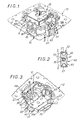
- FIGS. 1 to 18 illustrate, by way of example, the application of the invention in the case where the electrical equipment 10 to be embedded is a switch.
- the housing 11 is formed of two parts, namely, a lower portion 11A, forming a base, and a top portion 11B, forming a cover.
- FIG. 1 As it is visible on the figure 1 , it is equipped, in front, that is to say the upper face of its upper portion 11B, a tilting member 13, which, for the control of the underlying mechanism, is pivotally mounted on this part 11B superior, under the control of a finger of maneuver, not shown, available to the user.
- a tilting member 13 which, for the control of the underlying mechanism, is pivotally mounted on this part 11B superior, under the control of a finger of maneuver, not shown, available to the user.
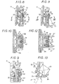
- the lower portion 11A On two opposite sides of its lower face, the lower portion 11A, forming a base, of the housing 11, has two connection areas C each giving access to two connection terminals 15, as shown schematically for one of them on the figure 13 , with, for each of these connection terminals 15, two cable entries 16 each adapted to the engagement of any electrical conductor 17, as shown schematically in broken lines on this figure 13 .
- the lower portion 11A of the housing 11 comprises, on each of its two lateral faces, a disconnection zone D which involves two disconnecting members 18, at a rate of one by connection terminal 15.
- each connection zone C is isolated from the corresponding disconnection zone D by a tab 20 which, coming from one piece of the housing 11, and, more precisely, from the lower portion 11A thereof protrudes obliquely outwardly along the corresponding edge of this lower portion 11A.
- this tongue 20 extends globally rounded, and, more specifically, convex, from one to the other of the ends of the corresponding edge of the lower portion 11 of the housing 11.
- the housing 11 of this electrical equipment 10 is equipped, laterally , at least one claw 22, which, under the control of a screw 23, and according to arrangements described in more detail later, is mounted movably between a retracted position, for which it lends itself to such engagement, in s then extending substantially in the overall contour of the housing 11, as shown in FIGS. Figures 1 to 3 , 8 and 10 , and an extended position, for which, projecting out of this contour, as shown on the Figures 11 and 12 on the contrary, it opposes any release of this electrical equipment 10 out of this housing, then biting into the side wall of the latter.
- two claws 22 are provided, in diametrically opposite positions with respect to each other, and for each of these claws 22, there is a screw 23.
- the two claws 22 extend crosswise relative to the connection areas C and disconnection D.
- resilient return means are associated with each of the claws 22, and they permanently urge such a claw 22 towards its retracted position.
- each of the claws 22 has, generally, a U-shaped configuration, with a middle portion 24, which has a hole 25 for the passage of the corresponding screw 23, and more precisely , for the passage of the shaft 26 of this screw 23, and two lateral legs 27, which each extend respectively on either side of this middle portion 24, and, on the other hand, the elastic return means associated with such a claw 22 comprises a pin spring 28 having a medial portion 30, by which it bears, directly or indirectly, on the housing 11, and two lateral wings 31, which each bear respectively on the two lateral legs 27 of the claw 22.
- the two claws 22 are identical to each other, and their elastic return means are exclusively constituted by the pin spring 28 associated therewith.
- the middle portion 24 of such a claw 22 extends generally obliquely to the direction of elongation of its side legs 27, and, between them, it has, on the side of these lateral jambs 27 turned outwards, an extension 32, which makes with its running part 33 a dihedron 34 of angle A obtuse, with the concavity of this dihedron 34 turned towards the side jambs 27.
- each of the claws 22 is pivotally mounted on an edge 35 of the housing 11, as is apparent from the Figures 8 and 11 for one of them.
- this edge 35 belongs to the upper part 11B of the housing 11.
- the hole 25 that has the middle part 24 of a claw 22 is elongated in a buttonhole along the line of greatest slope of this middle portion 24.
- the side jambs 27 of the claws 22 each comprise, substantially at a third of their height, a recess 38 by which they engage with the corresponding lateral wing 31 of the pin spring 28 associated with such a claw. 22.
- this recess 38 belongs to a notch affecting the corresponding slice of the lateral jambs 27.
- figure 20 it belongs to a beak that protrudes on this slice.
- the side jambs 27 of the claws 22 each comprise, at their free end, on this same edge, an anchoring point 39.
- the lateral legs 27 of the claws 22 each have, transversely, an inflection zone Z, which extends, for example substantially at their recess 38, and from which it follows that the distance separating them from one another is greater at their free end than in the vicinity of the middle portion 24 from which they are derived.
- figure 20 they are straight.
- the housing 11 Between the lateral jambs 27 of each of the claws 22, the housing 11, and more specifically, the lower portion 11 of this housing 11, has, in projection, a boss 40 by means of which the screw 23 which controls such a claw 22, this boss 40 having, for this purpose, a bore 41.
- this bore 41 is blind, and the screw 23 bites directly on its inner wall.
- the boss 40 is surmounted by a bracket 42, which belongs to the upper portion 11 B of the housing 11, and which, for the passage of the screw 23, has a bore 43.
- the edge 35 on which each of the claws 22 is pivotally mounted is the upper front edge of the corresponding console 42.
- each of the bosses 40 that the housing 11 has for the intervention of the screws 23 has, laterally, along the edges of its front face, that is to say along those edges of this front face which are parallel to the screws 23, over at least a portion of the height of this front face, and, in practice, over the entire height, fins 45, which, each respectively, and as it is best seen on the figure 2 extend in the direction of the side jambs 27 of the corresponding claw 22 to the vicinity thereof.
- the user who comes to handle the electrical equipment 10 is thus advantageously protected to the best of the relative aggressiveness of the claws 22 when they are in the retracted position.
- the pin spring 28 associated with each of the claws 22 bypasses, by its middle portion 30, the screw 23 which controls such a claw 22.
- this middle portion 30 has an open contour in a generally U-shaped configuration, and its concavity is facing outwards.
- the pin spring 28 is inserted, without however being necessarily tightened, between the two parts 11 A, 11 B constituting the housing 11, and, more precisely, between the upper surface of the boss 40 of the part concerned. 11 A lower of the housing 11 and the top of a recess 46 that has in correspondence the console 42 of its part 11 B upper.
- the middle part 30 of the pin spring 28 bears on the housing 11 only indirectly, via the screw 23 which controls the claw 22 in question, by directly bearing on this screw 23 , and, more precisely, on its shank 26, on a half-perimeter of the cross-section of this shank 26.
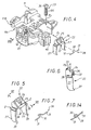
- the claws 22 are first put in place, then it is proceeded, following the same arrow F1, the establishment of the pin springs 28, and finally, following the arrow F2 of the figure 4 , it is proceeded to the establishment of the screws 23, which, therefore, ensure the maintenance of all.
- this pin spring 28 automatically returns to the retracted position the claw 22, in a tilting movement thereof opposite to the previous one.
- the middle part 30 of the pin spring 28 associated with each of the claws 22 has a closed contour in a helical turn.
- this middle portion 30 then extends inward with respect to the lateral wings 31 of this pin spring 28.
- the lower portion 11 of the housing 11 has, projecting on the upper face of its boss 40, for the seat of the middle portion 30 of the pin spring 28, a rib 48A, which, elongated along a semicircle, has a height that increases from one of its ends to the other, and, in a complementary manner, the upper portion 11 B of the housing 11 has a projection, on the top of the recess 46 of its console 42, a rib 48B of the same type, which, as shown schematically in broken lines on the figure 16 , complete the corresponding circle.
- At least one of the two parts 11A, 11B constituting the housing 11 has, projecting, around its rib 48A, 48B, at a distance from it, an enclosing wall 50 adapted to maintain the hairpin spring 28.
- this enveloping wall 50 belongs to the upper part 11 B of the housing 11.
- the ribs 48A, 48B of the parts 11A, 11B constituting the housing 11 facilitate the establishment of the pin spring 28 associated with the claws 22 and provide a good seat to it, marrying at best the shape of its middle part 30.
- FIGS 19 to 21 illustrate, by way of example, the application of the invention in the case where the housing 11 of the electrical equipment 10 to be embedded is in one and the same part.
- the pin spring 28 associated with the invention to each of the claws 22 is inserted through its middle portion 30 between a shoulder 52 of the housing 11 and a crimping flange 53 secured thereto.
- the crimping flange 53 belongs to a barrel 54, which, distinct from the casing 11, is counterbaked by the latter, having for this purpose a shoulder 55 at its opposite end, and with which the screw 23 is screwed in. who controls such a claw 22.
- figure 21 the crimping flange 53 is integral with the housing 11.
- this crimping flange 53 is folded laterally, by simple discharge.
- this pin spring 28 is, by way of example, of the type shown in FIG. figure 14 but, alternatively, it could as well be of the type shown in figure 7 .
Landscapes
- Engineering & Computer Science (AREA)
- Architecture (AREA)
- Civil Engineering (AREA)
- Structural Engineering (AREA)
- Casings For Electric Apparatus (AREA)
- Workshop Equipment, Work Benches, Supports, Or Storage Means (AREA)
- Telephone Set Structure (AREA)
Applications Claiming Priority (2)
| Application Number | Priority Date | Filing Date | Title |
|---|---|---|---|
| FR9714079A FR2770937B1 (fr) | 1997-11-10 | 1997-11-10 | Appareillage electrique a encastrer a fixation par griffes |
| FR9714079 | 1997-11-10 |
Publications (2)
| Publication Number | Publication Date |
|---|---|
| EP0915537A1 EP0915537A1 (fr) | 1999-05-12 |
| EP0915537B1 true EP0915537B1 (fr) | 2008-02-27 |
Family
ID=9513201
Family Applications (1)
| Application Number | Title | Priority Date | Filing Date |
|---|---|---|---|
| EP98402762A Expired - Lifetime EP0915537B1 (fr) | 1997-11-10 | 1998-11-06 | Appareillage électrique à encastrer à fixation par griffes |
Country Status (7)
| Country | Link |
|---|---|
| EP (1) | EP0915537B1 (es) |
| DE (1) | DE69839174T2 (es) |
| ES (1) | ES2301191T3 (es) |
| FR (1) | FR2770937B1 (es) |
| HU (1) | HU222460B1 (es) |
| PT (1) | PT915537E (es) |
| TR (1) | TR199802246A2 (es) |
Families Citing this family (9)
| Publication number | Priority date | Publication date | Assignee | Title |
|---|---|---|---|---|
| FR2796772B1 (fr) * | 1999-07-19 | 2002-02-08 | Legrand Sa | Griffe d'ancrage a deux zones geographiques d'action distinctes pour mecanisme electrique |
| DE19946416A1 (de) * | 1999-09-28 | 2001-04-05 | Kopp Heinrich Ag | Spreizkrallenvorrichtung für Installationsgeräte |
| ES2426775T3 (es) | 2007-01-23 | 2013-10-25 | Hager Electro S.A.S. | Garras de fijación para equipos eléctricos |
| DE102008023986B4 (de) | 2008-05-16 | 2013-01-24 | Berker Gmbh & Co. Kg | Elektrisches Installationsgerät |
| DE102008023983B4 (de) * | 2008-05-16 | 2013-02-28 | Berker Gmbh & Co. Kg | Elektrisches Installationsgerät |
| DE102009051266A1 (de) * | 2009-10-29 | 2011-06-01 | Abb Ag | UP-Installationsschalter mit Tragring |
| DE102013107704B3 (de) * | 2013-07-19 | 2014-05-08 | Insta Elektro Gmbh | Elektrisches/elektronisches Installationsgerät |
| ES2698503T3 (es) * | 2015-05-13 | 2019-02-05 | Giersiepen Gira Gmbh | Parte de base para aparatos de instalación eléctricos |
| ES2728090T3 (es) * | 2015-07-27 | 2019-10-22 | Comatec Consulting S R L | Fuente de alimentación con borne de conexión a palanca pivotante |
Family Cites Families (3)
| Publication number | Priority date | Publication date | Assignee | Title |
|---|---|---|---|---|
| DE2051184A1 (de) * | 1970-10-19 | 1972-04-20 | Berker Geb | Halterung für die Einspreizkrallen eines elektrischen Installationsgerätes |
| DE3603478A1 (de) * | 1986-02-05 | 1987-08-06 | Jung Albrecht Fa | Elektrisches installationsgeraet fuer unterputz |
| DK0654881T3 (da) * | 1993-11-12 | 1997-07-21 | Siemens Ag | Installationsapparat med ekspansionskløer, som kan føres tilbage |
-
1997
- 1997-11-10 FR FR9714079A patent/FR2770937B1/fr not_active Expired - Fee Related
-
1998
- 1998-11-05 TR TR1998/02246A patent/TR199802246A2/xx unknown
- 1998-11-06 EP EP98402762A patent/EP0915537B1/fr not_active Expired - Lifetime
- 1998-11-06 PT PT98402762T patent/PT915537E/pt unknown
- 1998-11-06 ES ES98402762T patent/ES2301191T3/es not_active Expired - Lifetime
- 1998-11-06 DE DE69839174T patent/DE69839174T2/de not_active Expired - Lifetime
- 1998-11-09 HU HU9802595A patent/HU222460B1/hu not_active IP Right Cessation
Also Published As
| Publication number | Publication date |
|---|---|
| HUP9802595A3 (en) | 2000-10-30 |
| FR2770937B1 (fr) | 2000-01-28 |
| ES2301191T3 (es) | 2008-06-16 |
| HU9802595D0 (en) | 1998-12-28 |
| DE69839174T2 (de) | 2009-02-19 |
| HU222460B1 (hu) | 2003-07-28 |
| FR2770937A1 (fr) | 1999-05-14 |
| TR199802246A3 (tr) | 1999-10-21 |
| HUP9802595A2 (hu) | 1999-10-28 |
| TR199802246A2 (xx) | 1999-10-21 |
| PT915537E (pt) | 2008-05-26 |
| EP0915537A1 (fr) | 1999-05-12 |
| DE69839174D1 (de) | 2008-04-10 |
Similar Documents
| Publication | Publication Date | Title |
|---|---|---|
| EP0505256B1 (fr) | Adaptateur en deux parties pour appareil électrique à brancher par une fiche sur un socle de prise de courant | |
| FR2662553A1 (fr) | Appareil electrique a rapporter sur un support par simple encliquetage. | |
| EP1531519B1 (fr) | Borne de raccordement électrique et appareil de protection électrique comportant une telle borne | |
| EP0915537A1 (fr) | Appareillage électrique à encastrer à fixation par griffes | |
| EP0099781B1 (fr) | Elément de coulissement et de verrouillage élastique pour frein à disque à étrier flottant supporté sur une colonnette axiale unique, et frein à disque équipé d'un tel élément | |
| FR2738676A1 (fr) | Appareil electrique a bornes de raccordement protegees par un diaphragme | |
| EP0495720B1 (fr) | Allume-cigares, notamment pour véhicules automobiles | |
| EP0511089B1 (fr) | Allume-cigares, notamment pour vehicules automobiles | |
| EP0940349B1 (fr) | Boítier composé d'éléments de boítier reliés l'un à l'autre de manière débrayable et articulée, notamment pour luminaire | |
| EP0259199B1 (fr) | Dispositif de raccordement électrique du moteur d'un haut-parleur | |
| EP0539293B1 (fr) | Hublot d'éclairage | |
| FR2563383A1 (fr) | Fiche de prise de courant a element de traction | |
| EP0921608B1 (fr) | Socle de prise de courant pour prise mobile, notamment pour cordon prolongateur | |
| EP0923176B1 (fr) | Accessoire de fixation à griffe, notamment pour boíte d'encastrement et boíte d'encastrement correspondante | |
| FR2734668A1 (fr) | Socle de prise de courant a interrupteur incorpore | |
| EP0225222B1 (fr) | Appareillage électrique à assemblage perfectionné | |
| EP0635649B1 (fr) | Ensemble articulé à ressort de rappel, son procédé de montage, et applications, notamment aux boîtiers pour appareillage électrique | |
| FR2744849A1 (fr) | Coffret, en particulier coffret electrique, a encastrer dans une cloison | |
| EP1071184B1 (fr) | Griffe d'ancrage à deux zones géographiques d'action distinctes pour mécanisme électrique | |
| EP0940893B1 (fr) | Douille pour ampoule électrique | |
| WO2008034654A1 (fr) | Disposiif d'eclairage a abat-jour amovible | |
| EP0670613A1 (fr) | Appareil électrique dont le mécanisme est logé dans un boîtier étanche comportant un couvercle et un volet | |
| FR2765660A1 (fr) | Accessoire de fixation pour grille de protection, notamment pour luminaire, et grille de protection equipee d'au moins un tel accessoire de fixation | |
| EP1396647A1 (fr) | Dispositif de fixation à quart de tour encliquetable | |
| EP1227559A1 (fr) | Agencement d'un dispositif de connexion électrique d'un luminaire encastrable |
Legal Events
| Date | Code | Title | Description |
|---|---|---|---|
| PUAI | Public reference made under article 153(3) epc to a published international application that has entered the european phase |
Free format text: ORIGINAL CODE: 0009012 |
|
| AK | Designated contracting states |
Kind code of ref document: A1 Designated state(s): BE DE ES PT |
|
| AX | Request for extension of the european patent |
Free format text: AL;LT;LV;MK;RO;SI |
|
| 17P | Request for examination filed |
Effective date: 19990611 |
|
| AKX | Designation fees paid |
Free format text: BE DE ES PT |
|
| RAP1 | Party data changed (applicant data changed or rights of an application transferred) |
Owner name: LEGRAND SNC Owner name: LEGRAND FRANCE |
|
| 17Q | First examination report despatched |
Effective date: 20070531 |
|
| GRAP | Despatch of communication of intention to grant a patent |
Free format text: ORIGINAL CODE: EPIDOSNIGR1 |
|
| RIC1 | Information provided on ipc code assigned before grant |
Ipc: H02G 3/18 20060101ALI20071101BHEP Ipc: H01R 24/16 20060101AFI20071101BHEP |
|
| GRAS | Grant fee paid |
Free format text: ORIGINAL CODE: EPIDOSNIGR3 |
|
| GRAA | (expected) grant |
Free format text: ORIGINAL CODE: 0009210 |
|
| AK | Designated contracting states |
Kind code of ref document: B1 Designated state(s): BE DE ES PT |
|
| REF | Corresponds to: |
Ref document number: 69839174 Country of ref document: DE Date of ref document: 20080410 Kind code of ref document: P |
|
| REG | Reference to a national code |
Ref country code: PT Ref legal event code: SC4A Free format text: AVAILABILITY OF NATIONAL TRANSLATION Effective date: 20080514 |
|
| REG | Reference to a national code |
Ref country code: ES Ref legal event code: FG2A Ref document number: 2301191 Country of ref document: ES Kind code of ref document: T3 |
|
| PLBE | No opposition filed within time limit |
Free format text: ORIGINAL CODE: 0009261 |
|
| STAA | Information on the status of an ep patent application or granted ep patent |
Free format text: STATUS: NO OPPOSITION FILED WITHIN TIME LIMIT |
|
| 26N | No opposition filed |
Effective date: 20081128 |
|
| BERE | Be: lapsed |
Owner name: LEGRAND SNC Effective date: 20081130 Owner name: LEGRAND FRANCE Effective date: 20081130 |
|
| PG25 | Lapsed in a contracting state [announced via postgrant information from national office to epo] |
Ref country code: BE Free format text: LAPSE BECAUSE OF NON-PAYMENT OF DUE FEES Effective date: 20081130 |
|
| PGFP | Annual fee paid to national office [announced via postgrant information from national office to epo] |
Ref country code: ES Payment date: 20141124 Year of fee payment: 17 |
|
| PGFP | Annual fee paid to national office [announced via postgrant information from national office to epo] |
Ref country code: PT Payment date: 20141021 Year of fee payment: 17 |
|
| REG | Reference to a national code |
Ref country code: PT Ref legal event code: MM4A Free format text: LAPSE DUE TO NON-PAYMENT OF FEES Effective date: 20160506 |
|
| PG25 | Lapsed in a contracting state [announced via postgrant information from national office to epo] |
Ref country code: PT Free format text: LAPSE BECAUSE OF NON-PAYMENT OF DUE FEES Effective date: 20160506 |
|
| REG | Reference to a national code |
Ref country code: ES Ref legal event code: FD2A Effective date: 20161228 |
|
| PGFP | Annual fee paid to national office [announced via postgrant information from national office to epo] |
Ref country code: DE Payment date: 20161115 Year of fee payment: 19 |
|
| PG25 | Lapsed in a contracting state [announced via postgrant information from national office to epo] |
Ref country code: ES Free format text: LAPSE BECAUSE OF NON-PAYMENT OF DUE FEES Effective date: 20151107 |
|
| REG | Reference to a national code |
Ref country code: DE Ref legal event code: R119 Ref document number: 69839174 Country of ref document: DE |
|
| PG25 | Lapsed in a contracting state [announced via postgrant information from national office to epo] |
Ref country code: DE Free format text: LAPSE BECAUSE OF NON-PAYMENT OF DUE FEES Effective date: 20180602 |