EP0915548A2 - Dispositif redresseur avec circuit de protection et procédé de mise hors circuit d'un dispositif redresseur - Google Patents
Dispositif redresseur avec circuit de protection et procédé de mise hors circuit d'un dispositif redresseur Download PDFInfo
- Publication number
- EP0915548A2 EP0915548A2 EP98117680A EP98117680A EP0915548A2 EP 0915548 A2 EP0915548 A2 EP 0915548A2 EP 98117680 A EP98117680 A EP 98117680A EP 98117680 A EP98117680 A EP 98117680A EP 0915548 A2 EP0915548 A2 EP 0915548A2
- Authority
- EP
- European Patent Office
- Prior art keywords
- rectifier
- current
- branch
- currents
- sum
- Prior art date
- Legal status (The legal status is an assumption and is not a legal conclusion. Google has not performed a legal analysis and makes no representation as to the accuracy of the status listed.)
- Withdrawn
Links
Images
Classifications
-
- H—ELECTRICITY
- H02—GENERATION; CONVERSION OR DISTRIBUTION OF ELECTRIC POWER
- H02H—EMERGENCY PROTECTIVE CIRCUIT ARRANGEMENTS
- H02H7/00—Emergency protective circuit arrangements specially adapted for specific types of electric machines or apparatus or for sectionalised protection of cable or line systems, and effecting automatic switching in the event of an undesired change from normal working conditions
- H02H7/10—Emergency protective circuit arrangements specially adapted for specific types of electric machines or apparatus or for sectionalised protection of cable or line systems, and effecting automatic switching in the event of an undesired change from normal working conditions for converters; for rectifiers
- H02H7/12—Emergency protective circuit arrangements specially adapted for specific types of electric machines or apparatus or for sectionalised protection of cable or line systems, and effecting automatic switching in the event of an undesired change from normal working conditions for converters; for rectifiers for static converters or rectifiers
- H02H7/125—Emergency protective circuit arrangements specially adapted for specific types of electric machines or apparatus or for sectionalised protection of cable or line systems, and effecting automatic switching in the event of an undesired change from normal working conditions for converters; for rectifiers for static converters or rectifiers for rectifiers
- H02H7/1255—Emergency protective circuit arrangements specially adapted for specific types of electric machines or apparatus or for sectionalised protection of cable or line systems, and effecting automatic switching in the event of an undesired change from normal working conditions for converters; for rectifiers for static converters or rectifiers for rectifiers responsive to internal faults, e.g. by monitoring ripple in output voltage
-
- H—ELECTRICITY
- H02—GENERATION; CONVERSION OR DISTRIBUTION OF ELECTRIC POWER
- H02H—EMERGENCY PROTECTIVE CIRCUIT ARRANGEMENTS
- H02H7/00—Emergency protective circuit arrangements specially adapted for specific types of electric machines or apparatus or for sectionalised protection of cable or line systems, and effecting automatic switching in the event of an undesired change from normal working conditions
- H02H7/10—Emergency protective circuit arrangements specially adapted for specific types of electric machines or apparatus or for sectionalised protection of cable or line systems, and effecting automatic switching in the event of an undesired change from normal working conditions for converters; for rectifiers
- H02H7/12—Emergency protective circuit arrangements specially adapted for specific types of electric machines or apparatus or for sectionalised protection of cable or line systems, and effecting automatic switching in the event of an undesired change from normal working conditions for converters; for rectifiers for static converters or rectifiers
- H02H7/1203—Circuits independent of the type of conversion
- H02H7/1206—Circuits independent of the type of conversion specially adapted to conversion cells composed of a plurality of parallel or serial connected elements
Definitions
- the present invention relates to a rectifier system with a Protection circuit for switching off in case of overcurrent or short circuit according to the The preamble of claim 1 and a method for switching off a such rectifier system according to the preamble of claim 6.
- Rectifier systems of the type in question are used to supply power to e.g. Electrolysis or electroplating systems used.
- the ones in these plants The nominal currents that occur are between 1 and 300 kA. Therefore, usually several parallel branches are used, in each branch a transformer, a rectifier and a shutdown relay is arranged. There is also one in each branch Device for detecting the current flowing through the branch.
- an overload shutdown of the Rectifier in a branch if a current is detected that is greater than that Is 1.1 times the nominal rectifier current.
- the overload shutdown takes place in one Delayed range between 1.1 to 2.5 times the rated current because the Rectifiers can cope with such currents for a short time without destruction. Falls in If a rectifier branch fails due to a defect, it will until a regulation intervenes, the remaining rectifier branches are temporarily overloaded, but this is permitted for this short period of time. With a detected branch current with a A value greater than 2.5 times the nominal rectifier current is switched off undelayed, since currents of this magnitude are already very fast Destroy rectifier.
- the object of the present invention is to provide a rectifier system with a Protection circuit and a method for switching off a rectifier system to be specified in the event of an overload or short circuit a faultless and fast The system is switched off.
- This task is performed by a rectifier system with the characteristics of Claim 1 and a method with the steps of claim 6 solved.
- the protection circuit has a current detection device for detecting the System current of the rectifier system, which is defined by the sum of the Output currents of all parallel branches.
- the protective circuit also has a Control circuit on which the relays of all branches in response to the detected Rectifier branch currents and the detected system current controls.
- This solution is based on the realization that it is advantageous to have one Shutdown of the rectifier system not only depending on the detected Rectifier branch currents, but also the system current Rectifier system to be considered for a shutdown process. This offers the Advantage that additional information regarding the currents flowing in the system is present, which can be used to make the shutdown process error-free and to perform quickly.
- the Control device a comparison device to the sum of the detected To compare rectifier branch currents with the detected system current. This enables an immediate determination of whether there is a short circuit in a rectifier occurred because only in this case the detected system current is smaller than that Sum of the detected rectifier branch currents.
- a transformer is preferably the rectifier in at least one branch upstream, whereby the voltage to be processed by the rectifier considerably reduced and cheaper rectifiers can be used.
- the current detection device for detecting the Rectifier branch current between the transformer and the rectifier is arranged, which makes it possible to monitor a large area.
- the inventive method according to claim 6 is characterized that the switches of all parallel branches are switched off without delay, if the system current, which is defined as the sum of the output currents of all parallel branches, exceeds a threshold or the system current is less than the sum of the currents flowing into each rectifier.
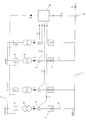
- the rectifier system comprises a high-voltage busbar 1 to which one AC voltage with a voltage amplitude of approximately 1 kV to several 100 kV is created.
- the high voltage busbar 1 is a variety of parallel branches 2 connected to a low-voltage busbar 3.
- the Voltage on the low-voltage busbar 3 is depending on Application between a few volts up to 1000 V.
- In each branch 2 are serial one behind the other a switch 4, an AC transformer 5, a Current detection device 6 and a rectifier 7 connected.
- every branch is located between the rectifier 7 and the low-voltage busbar 3 another switch to the branch also from the low voltage side isolate here.
- the currents I 1 to I 4 flowing in the parallel branches through the rectifiers 7 are measured inductively by the current detection devices 6, for example.
- the current detection devices emit signals i 1 to i 4 , which correspondingly represent the currents flowing through the parallel branches.
- a control device 8 receives the signals i 1 to i 4 and a signal i 5 from a system current detection device 9, which is a measure of the system current I 5 , which is formed from the sum of the currents I 1 to I 4 of all parallel branches.
- the control device 8 is connected to each switch 4 of the parallel branches 2 in order to transmit a control signal S to the switch for performing a switching operation.
- the switch is a single-pole switch, which can be switched between an open and a closed state.
- the switch 4 the transformers 5, the.
- Current detection devices 6 and 9 and the rectifiers 7 conventional: in Components known from the prior art are. Their structure and how they work are known to the person skilled in the art even without a detailed description.
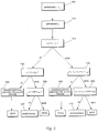
- a step 100 or 101 the currents I 1 to I 4 and the system current I 5 are first detected.
- the system current I 5 is compared with the sum of the currents I 1 to I 4 . If it is determined in step 102 that the system current does not match the sum of the rectifier branch currents, it is checked in step 103 whether the sum of the rectifier branch currents is substantially larger, ie greater than the system current plus one tenth of the system nominal current I 5N . If this is the case, there is a short circuit in a rectifier, whereupon all branches are immediately switched off in a step 108. This is done by outputting a corresponding control signal S to the switches 4 in order to cause their switches to change to the open state.
- the control device If the sum of the rectifier branch currents is only slightly greater than the system current, for example by one twentieth of the system nominal current I 5N , which is checked in a step 109, the control device outputs an acoustic and / or optical warning signal (step 110).
- step 104 If it was determined in step 102 that the system current is equal to the sum of all rectifier branch currents, it is checked in a step 104 whether the system current I 5 is greater than 1.1 times the system nominal current I 5N . If this is the case, all branches are switched off again immediately, otherwise it is checked whether the system current exceeds 1.05 times the system nominal current (step 106). When this threshold value is exceeded, an acoustic and / or visual warning signal is issued to the operating personnel to indicate that the system is in a critical but still operational state. The operating personnel can then check whether there is possibly a measurement value error, caused, for example, by temperature drift, and, if necessary, rectify this error without the rectifier system having to be switched off.
- the rectifier system according to the invention and the inventive method an error-free and fast shutdown of the Allow system, while ensuring that measurement errors are not an unnecessary erroneous shutdown of the rectifier system.
Landscapes
- Engineering & Computer Science (AREA)
- Power Engineering (AREA)
- Rectifiers (AREA)
- Protection Of Static Devices (AREA)
- Emergency Protection Circuit Devices (AREA)
Applications Claiming Priority (2)
| Application Number | Priority Date | Filing Date | Title |
|---|---|---|---|
| DE1997149359 DE19749359A1 (de) | 1997-11-07 | 1997-11-07 | Gleichrichteranlage mit Schutzschaltung und Verfahren zum Abschalten einer Gleichrichteranlage |
| DE19749359 | 1997-11-07 |
Publications (2)
| Publication Number | Publication Date |
|---|---|
| EP0915548A2 true EP0915548A2 (fr) | 1999-05-12 |
| EP0915548A3 EP0915548A3 (fr) | 1999-12-29 |
Family
ID=7848006
Family Applications (1)
| Application Number | Title | Priority Date | Filing Date |
|---|---|---|---|
| EP98117680A Withdrawn EP0915548A3 (fr) | 1997-11-07 | 1998-09-18 | Dispositif redresseur avec circuit de protection et procédé de mise hors circuit d'un dispositif redresseur |
Country Status (2)
| Country | Link |
|---|---|
| EP (1) | EP0915548A3 (fr) |
| DE (1) | DE19749359A1 (fr) |
Cited By (1)
| Publication number | Priority date | Publication date | Assignee | Title |
|---|---|---|---|---|
| CN105322506A (zh) * | 2014-06-26 | 2016-02-10 | 沈阳铝镁设计研究院有限公司 | 一种逆流保护整流机组 |
Families Citing this family (1)
| Publication number | Priority date | Publication date | Assignee | Title |
|---|---|---|---|---|
| DE102023206268A1 (de) | 2023-07-03 | 2025-01-09 | Robert Bosch Gesellschaft mit beschränkter Haftung | Elektrolysesystem und Verfahren zum Betreiben eines solchen Elektrolysesystems |
Family Cites Families (4)
| Publication number | Priority date | Publication date | Assignee | Title |
|---|---|---|---|---|
| US4475150A (en) * | 1982-04-28 | 1984-10-02 | General Electric Company | Coordinated load commutated inverter protection system |
| JP2750213B2 (ja) * | 1990-09-10 | 1998-05-13 | 株式会社日立製作所 | 半導体電力変換システム |
| US5206801A (en) * | 1991-09-18 | 1993-04-27 | Flick John R | Ac/dc converter fault detector |
| US5523938A (en) * | 1995-06-07 | 1996-06-04 | Sundstrand Corporation | Differential current fault protection for an AC/DC hybrid system and method therefor |
-
1997
- 1997-11-07 DE DE1997149359 patent/DE19749359A1/de not_active Withdrawn
-
1998
- 1998-09-18 EP EP98117680A patent/EP0915548A3/fr not_active Withdrawn
Cited By (1)
| Publication number | Priority date | Publication date | Assignee | Title |
|---|---|---|---|---|
| CN105322506A (zh) * | 2014-06-26 | 2016-02-10 | 沈阳铝镁设计研究院有限公司 | 一种逆流保护整流机组 |
Also Published As
| Publication number | Publication date |
|---|---|
| EP0915548A3 (fr) | 1999-12-29 |
| DE19749359A1 (de) | 1999-05-20 |
Similar Documents
| Publication | Publication Date | Title |
|---|---|---|
| DE69230465T2 (de) | Wechselrichtergerät und Verfahren zur Steuerung eines Wechselrichters mit einem Fehlerschutzsystem | |
| DE69015639T2 (de) | Fehlerstromschutzschalter. | |
| EP0295415A2 (fr) | Circuit de protection contre les courants de défaut | |
| DE4339241C2 (de) | Schaltungsanordnung zur Überwachung und Erkennung des Ausfalls des Nulleiters oder eines Phasenleiters eines Drehstromnetzes | |
| DE2911240A1 (de) | Ueberwachungsschaltung fuer eine zweikanalredundanz-steuervorrichtung | |
| DE4033444C2 (de) | Überstrom-Schutzeinrichtung für mittels Notstromversorgungen gespeiste Netze | |
| EP3485550B1 (fr) | Circuit de limitation de courant | |
| EP4367765B1 (fr) | Surveillance de courant de défaut pour un appareil de commutation à tension continue | |
| DE2533182B2 (de) | Schaltung zum feststellen ausgeloester sicherungen in stromversorgungsanlagen | |
| DE2508979C2 (de) | Anordnung für einen Schutzschalter mit einer Fehlerstrom-Überwachungseinheit und einer Erdungswiderstand-Überwachungseinheit | |
| DE4026799A1 (de) | Verfahren zur selektiven erfassung von fehlern der leiter in hoch- und hoechstspannungsnetzen | |
| EP0915548A2 (fr) | Dispositif redresseur avec circuit de protection et procédé de mise hors circuit d'un dispositif redresseur | |
| DE2742997A1 (de) | Verfahren zum ueberstromschutz von wechselrichtern in hochspannungs-gleichstrom-uebertragungsanlagen | |
| DE4040359C2 (de) | Einrichtung zum Kurzschlußschutz | |
| EP1308803B1 (fr) | Système de diagnostic d'alimentation | |
| DE2456073C3 (de) | Schutzanordnung fur Drehstromubertragungssysteme | |
| EP3913382B1 (fr) | Procédé et dispositif de détermination de la localisation d'un défaut non symétrique à trois pôles sur une ligne d'un réseau d'alimentation électrique triphasé | |
| DE19640821B4 (de) | Verfahren und Einrichtung zur Erfassung von Erdschlüssen | |
| WO2023160995A1 (fr) | Procédé et système de test de fonctionnalité d'un interrupteur à semi-conducteurs | |
| DE19612992C2 (de) | Verfahren zum Erfassen eines Fehlers auf einem durch Leistungsschalter begrenzten Abschnitt einer elektrischen Energieversorgungsleitung | |
| DE4322845A1 (de) | Anordnung zur Messung von Fehlerströmen in Verbraucherstromkreisen oder dergleichen | |
| DE2708844B2 (de) | Schutzgerät für eine Generator-Turbineneinheit gegen Überbeanspruchung der WeUe | |
| DE3813538A1 (de) | Schaltungsanordnung zum ueberwachten betrieb zweier wechselstromverbraucher ueber eine gemeinsame speiseleitung | |
| DE2062854C3 (de) | Überwachungseinrichtung für Leitungen zwischen einem Mehrphasen-Spannungswandler und einer Netzschutz-Meßeinrichtung | |
| DE2648357C3 (de) | Schaltungsanordnung zur Erfassung von Erdschlüssen in kompensierten Hochspannungsnetzen |
Legal Events
| Date | Code | Title | Description |
|---|---|---|---|
| PUAI | Public reference made under article 153(3) epc to a published international application that has entered the european phase |
Free format text: ORIGINAL CODE: 0009012 |
|
| AK | Designated contracting states |
Kind code of ref document: A2 Designated state(s): BE DE DK ES FI FR GB GR IE IT LU NL SE |
|
| AX | Request for extension of the european patent |
Free format text: AL;LT;LV;MK;RO;SI |
|
| RAP1 | Party data changed (applicant data changed or rights of an application transferred) |
Owner name: DEGUSSA-HUELS AKTIENGESELLSCHAFT |
|
| PUAL | Search report despatched |
Free format text: ORIGINAL CODE: 0009013 |
|
| AK | Designated contracting states |
Kind code of ref document: A3 Designated state(s): AT BE CH CY DE DK ES FI FR GB GR IE IT LI LU MC NL PT SE |
|
| AX | Request for extension of the european patent |
Free format text: AL;LT;LV;MK;RO;SI |
|
| 17P | Request for examination filed |
Effective date: 20000603 |
|
| AKX | Designation fees paid |
Free format text: BE DE DK ES FI FR GB GR IE IT LU NL SE |
|
| RAP1 | Party data changed (applicant data changed or rights of an application transferred) |
Owner name: DEGUSSA AG |
|
| STAA | Information on the status of an ep patent application or granted ep patent |
Free format text: STATUS: THE APPLICATION HAS BEEN WITHDRAWN |
|
| 18W | Application withdrawn |
Effective date: 20041227 |