EP0915549B1 - Dispositif d'écoulement - Google Patents
Dispositif d'écoulement Download PDFInfo
- Publication number
- EP0915549B1 EP0915549B1 EP19980119067 EP98119067A EP0915549B1 EP 0915549 B1 EP0915549 B1 EP 0915549B1 EP 19980119067 EP19980119067 EP 19980119067 EP 98119067 A EP98119067 A EP 98119067A EP 0915549 B1 EP0915549 B1 EP 0915549B1
- Authority
- EP
- European Patent Office
- Prior art keywords
- flow device
- flow
- motor
- supply voltage
- evaluation unit
- Prior art date
- Legal status (The legal status is an assumption and is not a legal conclusion. Google has not performed a legal analysis and makes no representation as to the accuracy of the status listed.)
- Expired - Lifetime
Links
- 238000011156 evaluation Methods 0.000 claims description 40
- 238000001514 detection method Methods 0.000 claims description 33
- 238000012806 monitoring device Methods 0.000 claims description 14
- 230000006870 function Effects 0.000 claims description 9
- 238000000034 method Methods 0.000 claims description 8
- 238000012360 testing method Methods 0.000 claims description 7
- 238000012544 monitoring process Methods 0.000 claims description 5
- 238000013021 overheating Methods 0.000 description 6
- 238000005259 measurement Methods 0.000 description 3
- 230000032683 aging Effects 0.000 description 2
- 238000010586 diagram Methods 0.000 description 2
- 238000004519 manufacturing process Methods 0.000 description 2
- 230000003287 optical effect Effects 0.000 description 2
- 230000008439 repair process Effects 0.000 description 2
- 208000032368 Device malfunction Diseases 0.000 description 1
- 230000006978 adaptation Effects 0.000 description 1
- 238000004378 air conditioning Methods 0.000 description 1
- 238000010276 construction Methods 0.000 description 1
- 230000001419 dependent effect Effects 0.000 description 1
- 238000011161 development Methods 0.000 description 1
- 230000018109 developmental process Effects 0.000 description 1
- 239000000428 dust Substances 0.000 description 1
- 230000002349 favourable effect Effects 0.000 description 1
- 238000010438 heat treatment Methods 0.000 description 1
- 238000009434 installation Methods 0.000 description 1
- 238000003754 machining Methods 0.000 description 1
- 230000007257 malfunction Effects 0.000 description 1
- 238000000691 measurement method Methods 0.000 description 1
- 230000002093 peripheral effect Effects 0.000 description 1
- 230000008672 reprogramming Effects 0.000 description 1
- 230000000717 retained effect Effects 0.000 description 1
- 230000001960 triggered effect Effects 0.000 description 1
Images

Classifications
-
- H—ELECTRICITY
- H02—GENERATION; CONVERSION OR DISTRIBUTION OF ELECTRIC POWER
- H02H—EMERGENCY PROTECTIVE CIRCUIT ARRANGEMENTS
- H02H7/00—Emergency protective circuit arrangements specially adapted for specific types of electric machines or apparatus or for sectionalised protection of cable or line systems, and effecting automatic switching in the event of an undesired change from normal working conditions
- H02H7/08—Emergency protective circuit arrangements specially adapted for specific types of electric machines or apparatus or for sectionalised protection of cable or line systems, and effecting automatic switching in the event of an undesired change from normal working conditions for dynamo-electric motors
- H02H7/093—Emergency protective circuit arrangements specially adapted for specific types of electric machines or apparatus or for sectionalised protection of cable or line systems, and effecting automatic switching in the event of an undesired change from normal working conditions for dynamo-electric motors against increase beyond, or decrease below, a predetermined level of rotational speed
-
- H—ELECTRICITY
- H02—GENERATION; CONVERSION OR DISTRIBUTION OF ELECTRIC POWER
- H02H—EMERGENCY PROTECTIVE CIRCUIT ARRANGEMENTS
- H02H7/00—Emergency protective circuit arrangements specially adapted for specific types of electric machines or apparatus or for sectionalised protection of cable or line systems, and effecting automatic switching in the event of an undesired change from normal working conditions
- H02H7/08—Emergency protective circuit arrangements specially adapted for specific types of electric machines or apparatus or for sectionalised protection of cable or line systems, and effecting automatic switching in the event of an undesired change from normal working conditions for dynamo-electric motors
- H02H7/0833—Emergency protective circuit arrangements specially adapted for specific types of electric machines or apparatus or for sectionalised protection of cable or line systems, and effecting automatic switching in the event of an undesired change from normal working conditions for dynamo-electric motors for electric motors with control arrangements
Definitions
- the invention relates to a flow device, in particular suction device, with the features of the preamble of claim 1.
- Such flow devices are, for example, suction devices, wherein the flow channel is formed by a suction line or a suction hose.
- Suction devices of this type are used inter alia in machining production processes to suck the chips lifted from the workpiece.
- the detection of the operating parameters is used to monitor the flow device, wherein in addition to motor current and motor speed of the flow channel cross section are detected as parameters.
- the evaluation unit for each measured motor current or for each measured engine speed can determine the associated standard value from the other operating parameters and compare it with the actually measured value. Inadmissible operating states can be detected quickly in this way, so that appropriate countermeasures can be taken.
- the flow channel cross-section of the detection device is detected as an operating parameter in an advantageous manner, since thus a changed flow channel cross-section is included in the standard value and allows a correct assessment of the operating state.
- Characterized in that the flow channel cross-section can be predetermined by means of a setting switch, is for its detection no complex sensor necessary. Since the flow channel cross section is usually unchanged, can be dispensed with in this case in favor of the reduced cost of an automatic detection.
- the determined standard value is the minimum engine speed.
- About the speed of the motor can also be deduced the flow velocity of the flow medium in the flow channel.
- the engine speed is detected by means of a permanently excited measuring coil of the detection device, wherein the measuring coil is in magnetic contact with rotor blades arranged on the rotor. It is a simple and reliable way of measuring speed.
- the setting switch is formed by a potentiometer, which expediently has a plurality of detent positions and forms a tap changer together with the evaluation unit.
- a potentiometer which expediently has a plurality of detent positions and forms a tap changer together with the evaluation unit.
- the power supply voltage supplying the motor can be detected by the detection device as Beriebparameter. Impermissible fluctuations in the supply voltage are thereby detected.
- the supply voltage is in the form of an alternating voltage. This could for example be obtained from the usual 230 volt network, which is normally used for energy supply in buildings.
- a plurality of measured values can be recorded and then averaged to a half-wave mean value. In this way, large measurement inaccuracies can be avoided.
- the evaluation unit has a programmable microcontroller.
- the evaluation unit can be changed in a simple manner by changing the programming in order to adapt it, for example, to new needs.
- the evaluation unit contains a memory, which is formed in particular by a read-only memory and / or EEPROM. This improves the flexibility of the evaluation unit.
- EEPROM In an EEPROM, the stored data is retained even after disconnecting the power supply.
- a characteristic field or a table can be stored, by means of which the standard value can be determined. In this way, a standard value can be determined for each permissible operating state.
- a calibration device is provided by means of which the characteristic field is adaptable to new operating conditions. For example, this allows the characteristic field to be adapted to a changed ambient temperature at which the flow device is operated. Even after repair work or due to aging processes of the components of the flow device, a calibration may be necessary.
- the calibration device when the flow device is in operation, the calibration device triggers the calibration process on request, wherein the characteristic field is adapted to the currently available operating parameters.
- the characteristic field is adapted to the currently available operating parameters.
- no costly reprogramming of the characteristic field is necessary, but its adaptation is carried out automatically on the basis of the currently available operating parameters.
- the other permissible operating states are also redefined starting from the operating state detected during the calibration.
- the calibration device can only be operated by prior input of a code sequence in order to prevent accidental or unauthorized calibration.
- the calibration device is included in the evaluation unit, so that a more effective utilization of the installation space and the capacity of the evaluation unit is achieved.
- the data stored in the memory may be readable by means of a control device in order to check the correctness of the data or to find and correct any errors.
- a further advantageous measure consists in that the monitoring device performs a self-test after the application of the supply voltage, whereby the proper function of the flow device is checked and expediently the presence of an error is indicated, if appropriate. As a result, malfunctions of the flow device can already be determined when switching on.
- the motor is disconnected from the supply voltage in the event of overheating, wherein a renewed application of the supply voltage to the motor is possible only after the end of the overheating state.
- a flow device is a suction device which has a rotor that can be driven by an electric motor to generate the flow in a flow channel.
- the rotor is provided with rotor blades and thus constructed fan-like.
- the flow channel is usually formed by a flexible suction hose.
- suction devices are for example industrial or household vacuum cleaners.
- the flow device according to the invention could also be air conditioning systems, heating systems or the like.
- the flow device has a monitoring device 10 provided for monitoring the flow during operation, whose block diagram in FIG Fig. 1 is shown.
- the monitoring device 10 has a detection device 11, which is used to detect a plurality of operating parameters during operation of the flow device serves.
- the operating voltage used for feeding the motor, the motor speed, the motor current flowing through the motor and the flow channel cross section are preferably detected as operating parameters. In an alternative embodiment, it would also be possible to detect only the engine speed and the motor current.
- the detection of the flow channel cross-section is particularly useful if it is variable, e.g. by replacing a suction hose forming the flow channel with a suction device.
- the detection of the supply voltage is usually only control purposes, since these are usually limited to a certain value, such as. 230 V, is impressed.
- the detection of motor current and motor speed for monitoring is basically sufficient.
- the operating parameters detected by the detection device 11 are supplied for evaluation to an evaluation unit 12, which compares the measured engine speed or the measured motor current with a standard value determined from the other operating parameters.
- the evaluation unit 12 can perform an assessment of the current operating state of the flow device.
- the standard value are at least the engine speed or the operating parameters Motor current and, for example, additionally the flow channel cross-section and the supply voltage available.
- the detection device 11 comprises a speed detection unit 14, which serves to measure the instantaneous engine speed.
- the speed detection unit 14 includes a permanent-magnet measuring coil, which is in magnetic contact with the rotor blades of the rotor. As a result of the rotation of the rotor, the rotor vanes are moved past the measuring coil so that the magnetic field generated by the measuring coil changes and the number of rotor vanes moved by per unit time can be determined. Thus, the engine speed can be determined.
- the speed detection unit 14 could also other means for determining the engine speed, such as. B. a Hall element, which cooperates with a permanent magnet.
- the flow channel cross section could also be determined automatically by a corresponding sensor, which was omitted in the preferred embodiment in favor of a reduced component and cost.
- the setting switch 15 is formed by a potentiometer, which in particular has a plurality of locking positions, which can be switched between a plurality of specific flow channel cross-sections. Together with the evaluation unit 12, the potentiometer thereby forms a tap changer.
- the detection device 11 For detecting the motor current or the supply voltage, the detection device 11 comprises a current detection unit 18 and a voltage detection unit 19.
- the structure of the current or voltage detection unit 18 or 19 is basically arbitrary and can be adapted to the prevailing circumstances. For example, it should be considered whether the supply voltage is a DC or AC voltage.
- the supply voltage is in the form of an AC voltage, e.g. can be obtained from the conventional 230 volt voltage network.
- the motor current is therefore an alternating current.
- the half-wave average values of a plurality of successive half-waves of the motor current or of the supply voltage are averaged to an overall mean value. The more measured values per half-wave are recorded and the more half-wave averages are determined, the greater the accuracy of the overall mean value.
- the standard value is determined and compared with the measured motor current or the measured motor speed.
- the standard value can be obtained, for example, from a table or a characteristic field.
- the detection device 11 detects only the motor current and the Motroburniere, could be read from a table of a given speed associated motor current or vice versa. The standard value obtained in this way is then compared with the measured value (motor current or motor speed).
- the standard value is specified as a function of several operating parameters, the structure of the table or the characteristic field is more complex, but the determination of the standard value is based on the same principle.
- the evaluation unit 12 If the standard value determined in the evaluation unit deviates by an impermissible amount or factor from the measured value of the engine speed or the motor current, the evaluation unit 12 generates a warning signal in a signal output device 22.
- the signal output device 22 is formed by a signal horn, so that the warning signal is an acoustic warning tone. It goes without saying that the warning signal could also be optical or simultaneously acoustic and optical.
- the determined standard value could be, for example, the minimum engine speed. If the difference between the measured engine speed and the standard value formed by the minimum engine speed deviates by the impermissible amount or factor, for example because of a blockage of the flow channel and / or a filter device, the evaluation unit 12 would use the signal output device 22 Generate warning signal.
- the evaluation unit 12 has a programmable microcontroller 25 and a memory 26 expediently formed by a read-only memory and / or EEPROM. A characteristic field or a table is stored in the memory 26 which serves to determine the standard value by the microcontroller 25 of the evaluation unit 12.
- the standard value is read in particular from the table stored in the memory 26. This can then be compared with the measured motor current value and / or with the measured motor speed.
- the data stored in the memory can be read out with the aid of a control device in order to check their correctness and, if necessary, to be able to correct errors.
- a control device may be, for example, a computer that can output the data of the memory 26 on its screen.
- the flow device also includes a manually adjustable power control of the motor so that the power can be adjusted according to the given needs.
- a suction device is on this type the desired suction selected. Since the supply voltage is present here in the form of an alternating voltage, the power control of the motor is advantageously realized by a phase control. The structure and operation of such a phase control are already well known, so that is dispensed with a more detailed explanation at this point.
- the preferred embodiment has a calibration device 29, which is preferably included in the evaluation unit 12.
- the calibration device 29 is executed in the microcontroller 25 of the evaluation unit 12.
- the calibration device 29 could, of course, form a structural unit independent of the microcontroller 25. It would also be conceivable to form the calibration device 29 by means of a trimpotentiometer, via which the evaluation of the motor current can be changed.
- the calibration device 29 when the flow device is in operation, the calibration device 29 triggers the calibration process on request, wherein the table stored in the memory 26 is adapted to the currently available operating parameters.
- the table stored in the memory 26 is adapted to the currently available operating parameters.
- the calibration device can only be operated by prior input of a code sequence.
- the code sequence can be entered by means of the setting switch 15. If the calibration device 29 receives the correct code sequence, then the calibration process is started. The presence of a calibration request is queried in the present case only after switching on the flow device. Alternatively, however, it would also be possible to perform the query for a present calibration request cyclically, so that a calibration would be possible at any time.
- the emergency shutdown unit 32 To protect the flow device, it has an emergency shutdown unit 32, which disconnects it from the supply voltage when the motor overheats.
- the emergency shutdown unit 32 may include a temperature sensor. If a certain temperature limit value is exceeded, an interruption switch is then actuated in the emergency shutdown unit 32, which disconnects the motor from the supply voltage.
- the emergency shutdown unit 32 is controlled by the evaluation unit 12.
- the evaluation unit 12 receives a Temperaturmeßsignal, evaluates this and optionally actuates the breaker switch in Notabschalteisme 32. A renewed application of the supply voltage to the motor is possible here only after completion of the overheating state, so that a restart interlock of the motor is realized after overheating.
- the interruption switch can be actuated directly as a function of the engine temperature.
- the breaker could be a so-called bimetal switch.
- the monitoring device 10 When switching on the flow device, so after the Applying the supply voltage, the monitoring device 10 performs a test, wherein the proper function of the flow device is checked. For example, it may be determined whether a rotor blade is broken, whether all areas of the memory 26 can be accessed, or whether the detector 11 is operating properly. If there is an error this is stored in the memory 26 and can be read out via the control unit. According to the example, the signal output device 22 is additionally activated by the evaluation unit 12, so that the presence of an error for the operator is recognizable. The operator can then use the control device to determine the exact error and take appropriate action. It is understood that the signal output device 22 could also have a display panel which displays the exact error immediately, so that an additional query by means of the control device could be omitted.
- the microcontroller 25 of the evaluation unit 12 is connected to a supply and auxiliary control arrangement 35, which represents the necessary and advantageous peripheral connection of the microcontroller 25.
- the supply and auxiliary control arrangement 35 are, for example, the power supply and necessary for controlling the microcontroller clock generation realized.
- a reset circuit for resetting the microcontroller 25, a network synchronization or similar functional blocks may be provided in the supply and auxiliary control device 35.
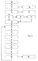
- step No. 50 the flow device is applied to the supply voltage. Subsequently, a query is made in step 51 as to whether the memory 26 of the evaluation unit 12 is to be read out by means of the control device. If this is the case, then the evaluation unit 12 the memory 26 for reading free and goes through the endless loop READ (step 52).
- step 51 is followed by step 53, in which it is queried whether or not the test performed by the monitoring device 10 to determine the proper functioning of the flow device has resulted in an error. If there is an error, the error is stored in the memory 26 in step 54 and the warning signal is output by means of the signal output device 22.
- step 53 is followed by step 55, which queries whether the input of the code sequence for starting the calibration device 29 takes place. If this query is answered in the affirmative, it is determined in the downstream query 56 whether the input of the code sequence was correct. If this is the case, step 57 is passed through during which the calibration process is carried out. Subsequently, the calibration data are loaded into the microcontroller 25 in step 58.
- step 57 Calibration data are loaded into the microcontroller 25 of the evaluation unit 12.
- the hose diameter is detected in step 59, which takes place in the present case by the predetermined value at the setting switch 15.
- the supply voltage, the motor current and the engine speed are then determined successively in the detection device 11.
- the standard value is determined as a function of the relevant operating parameters and compared with the measured engine speed or the measured motor current (step 63). If the measured engine speed or the measured motor current deviates from the determined standard value by the impermissible amount or factor, the warning signal is output via the signal output device 22 in step 64. If, on the other hand, the difference between the measured value and the determined standard value lies within the permissible range, then the warning signal is switched off.
- step 65 it is finally checked whether there is an overheating of the engine. If this is the case, the evaluation unit 12 is placed in an endless waiting loop, whereby the further operation of the motor is prevented (step 66).
- step 59 is followed again by step 59, in which the flow channel cross section is detected.
- Steps 59-65 are then sequentially executed during operation of the flow device, if the engine is not overheated. Only after switching off and restarting the flow device and the steps 50 - 58 are performed again.
Landscapes
- Control Of Electric Motors In General (AREA)
- Electrical Control Of Air Or Fuel Supplied To Internal-Combustion Engine (AREA)
- Combined Controls Of Internal Combustion Engines (AREA)
Claims (19)
- Dispositif d'écoulement, en particulier dispositif d'aspiration, comprenant un rotor, pouvant être entraîné par un moteur électrique, servant à produire un écoulement dans un canal d'écoulement, comprenant un système de surveillance (10) servant à surveiller l'écoulement lors du fonctionnement du dispositif d'écoulement, qui présente un système d'acquisition (11), qui acquiert au moins le régime du moteur et le courant de moteur comme paramètres de fonctionnement et les amène, pour évaluation, à une unité d'évaluation (12), dans laquelle le régime du moteur mesuré ou le courant du moteur mesuré est comparé à une valeur standard correspondante, qui est prédéfinie en fonction du ou des autres paramètres de fonctionnement, caractérisé en ce qu'un signal d'avertissement est généré lorsque la valeur mesurée diffère de la valeur standard déterminée d'une valeur ou d'un facteur non admissible, en ce qu'également la section transversale du canal d'écoulement est acquise, en tant que paramètre de fonctionnement par le système de d'acquisition (11) et peut être prédéfinie au moyen d'un commutateur de réglage (15).
- Dispositif d'écoulement selon la revendication 1, caractérisé en ce que la valeur standard déterminée est le régime minimal du moteur.
- Dispositif d'écoulement selon la revendication 1 ou 2, caractérisé en ce que le régime du moteur est acquis au moyen d'une bobine de mesure à excitation permanente du système d'acquisition (11), sachant que la bobine de mesure se trouve en contact magnétique avec des pales de rotor disposées au niveau du rotor.
- Dispositif d'écoulement selon l'une quelconque des revendications précédentes, caractérisé en ce que le commutateur de réglage (15) est formé par un potentiomètre, qui présente en particulier plusieurs positions d'enclenchement et qui forme conjointement avec l'unité d'évaluation (12) un commutateur à paliers.
- Dispositif d'écoulement selon l'une quelconque des revendications précédentes, caractérisé en ce que la tension d'alimentation alimentant le moteur est acquise par le système d'acquisition (11) en tant que paramètre de fonctionnement.
- Dispositif d'écoulement selon la revendication 5, caractérisé en ce que la tension d'alimentation se présente sous la forme d'une tension alternative.
- Dispositif d'écoulement selon la revendication 6, caractérisé en ce que, lors de l'acquisition du courant du moteur et de la tension d'alimentation, plusieurs valeurs de mesure sont enregistrées pendant une demi-onde du courant du moteur ou de la tension d'alimentation et sont ensuite moyennées en une valeur moyenne de demi-ondes.
- Dispositif d'écoulement selon la revendication 7, caractérisé en ce que lors de l'acquisition du courant du moteur et de la tension d'alimentation, les valeurs moyennes de demi-ondes de plusieurs demi-ondes se suivant les unes les autres sont moyennées en une valeur moyenne globale.
- Dispositif d'écoulement selon l'une quelconque des revendications 6 à 8, caractérisé en ce qu'un réglage de la puissance du moteur pouvant être réglé manuellement est prévu, lequel est réalisé en particulier par une commande par redressement à la sortie des phases.
- Dispositif d'écoulement selon l'une quelconque des revendications précédentes, caractérisé en ce que l'unité d'évaluation (12) présente un microcontrôleur (25) programmable.
- Dispositif d'écoulement selon l'une quelconque des revendications précédentes, caractérisé en ce que l'unité d'évaluation (12) comporte une mémoire (26), qui est formée en particulier par un EEPROM.
- Dispositif d'écoulement selon la revendication 11, caractérisé en ce qu'une table des caractéristiques ou un tableau sont enregistrés dans la mémoire (26) de l'unité d'évaluation (12), lesquels permettent de déterminer la valeur standard.
- Dispositif d'écoulement selon la revendication 12, caractérisé en ce qu'un système de calibrage (29) est présent, lequel permet d'adapter la table des caractéristiques aux nouvelles conditions de fonctionnement.
- Dispositif d'écoulement selon la revendication 13, caractérisé en ce que le système d'étalonnage (29) déclenche, lorsque le dispositif d'écoulement se trouve en fonctionnement, sur demande l'opération de calibrage, sachant que la table des caractéristiques est adaptée au paramètre de fonctionnement présent de manière instantanée.
- Dispositif d'écoulement selon la revendication 13 ou 14, caractérisé en ce que le système de calibrage (29) peut fonctionner seulement en entrant au préalable une séquence de codes.
- Dispositif d'écoulement selon l'une quelconque des revendications précédentes 13 à 15, caractérisé en ce que le système de calibrage (29) est compris dans l'unité d'évolution (12).
- Dispositif d'écoulement selon l'une quelconque des revendications 11 à 16, caractérisé en ce que les données enregistrées dans la mémoire (26) peuvent être lues au moyen d'un appareil de contrôle.
- Dispositif d'écoulement selon l'une quelconque des revendications précédentes, caractérisé en ce que le système de surveillance (10) exécute un test après l'application de la tension d'alimentation, sachant que le fonctionnement convenable du dispositif d'écoulement est vérifié et que, de manière appropriée, la présence d'une erreur est éventuellement indiquée.
- Dispositif d'écoulement selon l'une quelconque des revendications précédentes, caractérisé en ce que le moteur est séparé, en cas de surchauffe, de la tension d'alimentation, sachant qu'il est possible d'appliquer à nouveau sur le moteur la tension d'alimentation seulement une fois l'état de surchauffe passé.
Applications Claiming Priority (2)
| Application Number | Priority Date | Filing Date | Title |
|---|---|---|---|
| DE1997149478 DE19749478A1 (de) | 1997-11-08 | 1997-11-08 | Strömungsvorrichtung |
| DE19749478 | 1997-11-08 |
Publications (3)
| Publication Number | Publication Date |
|---|---|
| EP0915549A2 EP0915549A2 (fr) | 1999-05-12 |
| EP0915549A3 EP0915549A3 (fr) | 2000-05-31 |
| EP0915549B1 true EP0915549B1 (fr) | 2014-06-18 |
Family
ID=7848082
Family Applications (1)
| Application Number | Title | Priority Date | Filing Date |
|---|---|---|---|
| EP19980119067 Expired - Lifetime EP0915549B1 (fr) | 1997-11-08 | 1998-10-08 | Dispositif d'écoulement |
Country Status (2)
| Country | Link |
|---|---|
| EP (1) | EP0915549B1 (fr) |
| DE (1) | DE19749478A1 (fr) |
Families Citing this family (1)
| Publication number | Priority date | Publication date | Assignee | Title |
|---|---|---|---|---|
| DE10017861A1 (de) * | 1999-08-04 | 2001-03-15 | Ksb Ag | Störungsüberwachung |
Family Cites Families (3)
| Publication number | Priority date | Publication date | Assignee | Title |
|---|---|---|---|---|
| US4370690A (en) * | 1981-02-06 | 1983-01-25 | Whirlpool Corporation | Vacuum cleaner control |
| EP0479609A3 (en) * | 1990-10-05 | 1993-01-20 | Hitachi, Ltd. | Vacuum cleaner and control method thereof |
| DE4116407C2 (de) * | 1991-05-18 | 1994-05-19 | Preh Elektro Feinmechanik | Elektronische Staubsauger-Steuerschaltung |
-
1997
- 1997-11-08 DE DE1997149478 patent/DE19749478A1/de not_active Withdrawn
-
1998
- 1998-10-08 EP EP19980119067 patent/EP0915549B1/fr not_active Expired - Lifetime
Also Published As
| Publication number | Publication date |
|---|---|
| EP0915549A2 (fr) | 1999-05-12 |
| EP0915549A3 (fr) | 2000-05-31 |
| DE19749478A1 (de) | 1999-05-12 |
Similar Documents
| Publication | Publication Date | Title |
|---|---|---|
| EP1911058B1 (fr) | Commutateur de securite pour commander un dispositif relevant de la securite, afin de le mettre dans un etat de securite | |
| EP0770757B2 (fr) | Méthode pour actionner des vélums ou des choses pareilles par moteur électrique | |
| EP0284785B1 (fr) | Méthode et dispositif pour le contrôle de l'étanchéité de deux vannes disposées successivement sur un conduit de fluide | |
| DE102007048996B4 (de) | Steuersystem zum Steuern eines Leistungsgenerators mit Bestimmungsvorrichtung zur Erkennung, ob ein empfangener Befehlswert länger als eine zulässige Dauer unverändert geblieben ist | |
| DE69717971T2 (de) | Verfahren und schaltung zum testen von elektrischen antrieben | |
| WO1991019631A1 (fr) | Systeme d'essuie-glace | |
| DE102004018966B4 (de) | Reihenschlussmotor | |
| DE3037135A1 (de) | Auf einem mikrocomputer basierendes fehlererfassung- und anzeigesteuersystem | |
| DE102016011803B4 (de) | Testvorrichtung und Verfahren zur Überprüfung eines in einem Gerät angeordneten Vibrationsmotors | |
| DE69619318T2 (de) | Verfahren zur Detektion einer Fehlfunktion in einer Kühlerlüfteranlage | |
| DE102005037717B3 (de) | Verfahren und Vorrichtung zur Diagnose eines Außentemperatursensors | |
| EP0152770A1 (fr) | Dispositif de régulation surveillé | |
| EP3661402A1 (fr) | Procédé de fonctionnement d'un appareil d'aspiration et appareil d'aspiration | |
| DE4031708C2 (de) | Verfahren zur Differenzdruckregelung eines von einem Einphasen-Kondensatormotor angetriebenen Pumpsystems und Schaltungsanordnung zur Durchführung des Verfahrens | |
| DE4410735B4 (de) | Einrichtung mit einem Feuerungsautomaten | |
| EP2184830B1 (fr) | Dispositif de surveillance de la température d'un enroulement de courant multiphasé d'une machine électrique | |
| EP0915549B1 (fr) | Dispositif d'écoulement | |
| DE4211495A1 (de) | Vorrichtung zur drehmomentabschaltung eines kondensatormotors | |
| DE3834485C2 (fr) | ||
| DE102006000439A1 (de) | Verfahren zur Steuerung eines Motors eines akkubetriebenen Werkzeuggerätes | |
| DE102010002946A1 (de) | Verfahren und Vorrichtung zur Detektion einer Blockierung oder Schwergängigkeit eines Gleichstrommotors | |
| WO2007042159A1 (fr) | Systeme de commande pour machine electrique | |
| EP0640763B1 (fr) | Procédé de surveillance d'au moins une charge électrique | |
| DE4446996B4 (de) | Verfahren und Vorrichtung zum Löschen eines Fehlercodes in einer Steuereinheit für ein automatisches Getriebe eines Kraftfahrzeugs | |
| DE4123403C2 (de) | Schrittmotor-Treiberschaltung mit Ausfallsicherung |
Legal Events
| Date | Code | Title | Description |
|---|---|---|---|
| PUAI | Public reference made under article 153(3) epc to a published international application that has entered the european phase |
Free format text: ORIGINAL CODE: 0009012 |
|
| AK | Designated contracting states |
Kind code of ref document: A2 Designated state(s): DE FR GB IT |
|
| AX | Request for extension of the european patent |
Free format text: AL;LT;LV;MK;RO;SI |
|
| PUAL | Search report despatched |
Free format text: ORIGINAL CODE: 0009013 |
|
| AK | Designated contracting states |
Kind code of ref document: A3 Designated state(s): AT BE CH CY DE DK ES FI FR GB GR IE IT LI LU MC NL PT SE |
|
| AX | Request for extension of the european patent |
Free format text: AL;LT;LV;MK;RO;SI |
|
| 17P | Request for examination filed |
Effective date: 20000609 |
|
| AKX | Designation fees paid |
Free format text: DE FR GB IT |
|
| RAP1 | Party data changed (applicant data changed or rights of an application transferred) |
Owner name: TTS TOOLTECHNIC SYSTEMS AG & CO. KG |
|
| 17Q | First examination report despatched |
Effective date: 20080714 |
|
| REG | Reference to a national code |
Ref country code: DE Ref legal event code: R079 Ref document number: 59814548 Country of ref document: DE Free format text: PREVIOUS MAIN CLASS: H02H0007085000 Ipc: H02H0007080000 |
|
| RIC1 | Information provided on ipc code assigned before grant |
Ipc: H02H 7/08 20060101AFI20131219BHEP Ipc: H02H 7/093 20060101ALI20131219BHEP |
|
| GRAP | Despatch of communication of intention to grant a patent |
Free format text: ORIGINAL CODE: EPIDOSNIGR1 |
|
| INTG | Intention to grant announced |
Effective date: 20140129 |
|
| GRAS | Grant fee paid |
Free format text: ORIGINAL CODE: EPIDOSNIGR3 |
|
| GRAA | (expected) grant |
Free format text: ORIGINAL CODE: 0009210 |
|
| AK | Designated contracting states |
Kind code of ref document: B1 Designated state(s): DE FR GB IT |
|
| REG | Reference to a national code |
Ref country code: GB Ref legal event code: FG4D Free format text: NOT ENGLISH |
|
| REG | Reference to a national code |
Ref country code: DE Ref legal event code: R096 Ref document number: 59814548 Country of ref document: DE Effective date: 20140731 |
|
| REG | Reference to a national code |
Ref country code: DE Ref legal event code: R097 Ref document number: 59814548 Country of ref document: DE |
|
| PLBE | No opposition filed within time limit |
Free format text: ORIGINAL CODE: 0009261 |
|
| STAA | Information on the status of an ep patent application or granted ep patent |
Free format text: STATUS: NO OPPOSITION FILED WITHIN TIME LIMIT |
|
| 26N | No opposition filed |
Effective date: 20150319 |
|
| REG | Reference to a national code |
Ref country code: FR Ref legal event code: ST Effective date: 20150630 |
|
| PG25 | Lapsed in a contracting state [announced via postgrant information from national office to epo] |
Ref country code: FR Free format text: LAPSE BECAUSE OF NON-PAYMENT OF DUE FEES Effective date: 20141031 |
|
| PGFP | Annual fee paid to national office [announced via postgrant information from national office to epo] |
Ref country code: GB Payment date: 20150819 Year of fee payment: 18 |
|
| GBPC | Gb: european patent ceased through non-payment of renewal fee |
Effective date: 20161008 |
|
| PG25 | Lapsed in a contracting state [announced via postgrant information from national office to epo] |
Ref country code: GB Free format text: LAPSE BECAUSE OF NON-PAYMENT OF DUE FEES Effective date: 20161008 |
|
| PGFP | Annual fee paid to national office [announced via postgrant information from national office to epo] |
Ref country code: IT Payment date: 20170725 Year of fee payment: 20 |
|
| PGFP | Annual fee paid to national office [announced via postgrant information from national office to epo] |
Ref country code: DE Payment date: 20170818 Year of fee payment: 20 |
|
| REG | Reference to a national code |
Ref country code: DE Ref legal event code: R071 Ref document number: 59814548 Country of ref document: DE |