EP0915636A2 - Dispositif de ligne d'onde à élargissement radial avec de multiples surfaces planes - Google Patents
Dispositif de ligne d'onde à élargissement radial avec de multiples surfaces planes Download PDFInfo
- Publication number
- EP0915636A2 EP0915636A2 EP98309036A EP98309036A EP0915636A2 EP 0915636 A2 EP0915636 A2 EP 0915636A2 EP 98309036 A EP98309036 A EP 98309036A EP 98309036 A EP98309036 A EP 98309036A EP 0915636 A2 EP0915636 A2 EP 0915636A2
- Authority
- EP
- European Patent Office
- Prior art keywords
- length
- waveguide
- speaker
- maximum
- minimum
- Prior art date
- Legal status (The legal status is an assumption and is not a legal conclusion. Google has not performed a legal analysis and makes no representation as to the accuracy of the status listed.)
- Withdrawn
Links
Images


Classifications
-
- H—ELECTRICITY
- H04—ELECTRIC COMMUNICATION TECHNIQUE
- H04R—LOUDSPEAKERS, MICROPHONES, GRAMOPHONE PICK-UPS OR LIKE ACOUSTIC ELECTROMECHANICAL TRANSDUCERS; ELECTRIC HEARING AIDS; PUBLIC ADDRESS SYSTEMS
- H04R1/00—Details of transducers, loudspeakers or microphones
- H04R1/20—Arrangements for obtaining desired frequency or directional characteristics
- H04R1/22—Arrangements for obtaining desired frequency or directional characteristics for obtaining desired frequency characteristic only
- H04R1/30—Combinations of transducers with horns, e.g. with mechanical matching means, i.e. front-loaded horns
Definitions
- the present invention relates to waveguides and more particularly unique waveguide configurations utilizing a plurality of an even number of flat-surfaced segments which have unique geometric characteristics and may be constructed of light weight materials.
- Loudspeakers are well known and take the form of cones or horns. Conical loudspeakers have circular open ends and horns typically have rounded or straight edges such as rectangular open ends.
- United States Patent No. 4,811,403 illustrates various types of horns for ultralight loudspeakers.
- This patent describes a loudspeaker and enclosure assembly which includes a load bearing member exhibiting good thermal conductivity; at least one loudspeaker mounted on the load bearing member and in thermal engagement therewith; and its enclosure having walls formed of rigid lightweight material mounted on the load bearing member to enclose the at least one loudspeaker, whereby the assembly is easily moved and mounted and thermal energy generated by operation of the loudspeaker is effectively dissipated through the load bearing member.
- the enclosure may be a rigid foam-filled member defining a generally funnel-shaped bore therein to form a horn for the loudspeaker, whereby a modular construction of interchangeable integrally formed enclosures and horns can be achieved.
- this patent does not show the type of arrangement or assembly specifically claimed herein.
- the present invention is a waveguide for an acoustic speaker having a predetermined cone weight. It has a waveguide body having a speaker end and an open end and having a plurality of segments.
- the segments are substantially similar to one another, preferably identical, there being an even number of segments from four to twenty.
- Each of the segments have a flat surface in a plane parallel to the speaker end.
- ⁇ A an angle between the straight line length of the lower portion of the segment wall surface and a center line running down the center of the length of the waveguide
- the waveguide of the present invention has unique geometric characteristics. It is a full range waveguide which may be used with circular or other speaker cones is particularly effective with speaker cones and having arcuated segments as described in United States Patent No. 4,881,617 to the inventor herein dated November 21, 1989.
- the present invention waveguide has an even number of segments with inside wall surfaces which are flat.
- flat is meant that each inside wall of the segments has one dimension which is linear.
- These segments flare outwardly as to width and bend outwardly relative to a central axis along the center of the length of the waveguide.
- the segment inside walls, and the waveguide itself has a speaker end, that is, the end where the speaker's attached and an open end, the end furthest away from the speaker attachment location.
- the present invention waveguide may be viewed as having an overall length which can be divided into two length portions, a lower length which is closer to the speaker end and hereinafter referred to as the "speaker end length" and an outer length which begins at the end of the speaker end length and terminates at the open end, hereinafter referred to as the "open end length”.
- the speaker end length, L 1 is measured as a straight line by connecting the beginning point of a segment inside wall to a predetermined point in the arcing wall as viewed from a side view.
- the open end length, L 2 is a straight line measurement taken from the end of the speaker end length to the top or open end of the waveguide.
- the overall length, L 3 is the straight line length measured from the speaker end to the open end. All of these lengths are measured from a side view of a segment.
- the speaker end length of each segment is based in part on the weight of a speaker cone, w s , to be employed as well as the cross-sectional area of the speaker end of the waveguide itself, A SE .
- the minimum speaker end length is 0.7 times the speaker weight divided by the mass of air (0.0012 grams per cubic centimeters) times one over the cross-sectional area of the speaker end.
- the maximum speaker end length is utilizing the same formula but instead of 0.7 as the multiplier, 1.2 is the multiplier. In preferred embodiments, the maximum multiplier is 1.0.
- the open length is within the range of 0.7 to 1.3 times the speaker end length. It is typically about equal to the speaker end length but shorter or longer lengths may be used without exceeding the scope of the present invention. In any event, L 2 should be at least half of the length of L 1 or greater.
- angle A is no greater than 15°.
- angle A is no greater than 12° and angle B is about 1.8 to 2.2 times angle A. In most preferred embodiments angle B is approximately twice angle A.
- Figure 1 shows a front view and Figure 2 shows a side cut view of one preferred embodiment waveguide device of the present invention. Identical parts identically numbered.
- Figure 1 shows waveguide 1 having an outside octagonal wall 3.
- the exact configuration of octagonal wall 3 is not critical to the present invention. What is critical, is the shape of the inside wall 5, hereinafter referred to as segments, there are eight segments, namely, segments 7, 9, 11, 13, 15, 17, 19 and 21.
- the side cut view of waveguide 1 of Figure 1 shows that the speaker end has a much smaller opening than the open end, that the segments flare outwardly from speaker end to open end and thereby increase in width from speaker end to open end.
- Figure 3 shows a partial repeat view of Figure 2 with identical parts identically numbered but illustrates a central axis 31 about which all of the waveguide segments are symmetrically related to one another, i.e. opposite segments are mirror images of one another.
- line x is shown to further illustrate the increasing width of each segment, such as segment 9 and to also illustrate that if line x were taken parallel to the speaker end anywhere along segment 9, it would be a flat line.
- Figure 4 shows cut side view segment 13 and illustrates ⁇ A and ⁇ B relative to center line 31 (these angles are defined in more detail above).
- Speaker end length L 1 is illustrated in conjunction with ⁇ A and relative to segment 13 inside wall, as is open end length L 2 and ⁇ B.
- Overall straight line length L 1 is also illustrated.
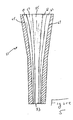
- Figure 5 shows a side cut view of another present invention waveguide 51 which has a much longer overall length and narrower angles but conforms to the formula set forth above.
- Waveguide 51 has a total of twelve segments and in this case because it is shown in a cut sectional view, it illustrates five whole segments, such as segments 55, 57, 59, 61 and 63 plus two half segments in their side view, segments 67 and 69.
- This waveguide may be formed of foam and have a skinned surface similar to the construction described above and will receive an acoustical speaker at speaker end 53.
- One embodiment of the specific characteristics of a waveguide shown in Figure 5 is discussed below in detail in conjunction with Example 3.
- a 40° x 40° waveguide of the present invention contains eight equal segments such as is illustrated in Figures 1 through 4.
- the overall length of the speaker as measured in a straight line is approximately 26 inches.
- the speaker end has a cross-sectional opening of 6.8 inches and the speaker end length, L 1 , is approximately 13.5 inches and has an angle ⁇ A of 10°.
- the open end length, L 2 is approximately 14 inches and has an angle ⁇ B of 20°.
- the open end has a cross-sectional opening of about 21.5 inches.
- the total speaker straight line length is approximately 25.7 inches.
- This 40° x 40° waveguide (40° total angle of opening at open end taking two measurements at right angles to one another) is constructed of polyurethane foam with a urethane skin coating. Attached to a speaker of the United States Patent No. 4,881,617, Faraone speaker, with arcuated segments, the waveguide provides excellent full range projection with minimal distortion.
- a 40° x 40° cone is constructed in accordance with Example 1 but utilizing sixteen segments instead of eight.
- the waveguide is constructed of foam with integral skin and includes mounting brackets embedded therein for speaker support and attachment.
- Another, elongated, present invention waveguide of the type set forth in Figure 5 is constructed with twelve segments and has a total length of about 27 inches. Its speaker end has a cross-sectional opening of 2.8 inches and an open end cross-sectional opening of about 9 inches. ⁇ A is 5° and ⁇ B is 12°. The open end thus has a 24° x 24° opening.
- This waveguide has no angle change for the lower half of the L 1 portion of each segment, and then the angle increases from 0° to 5° over the remaining length of that L 1 portion of each segment. Thus, about 1/4 of the total length of the waveguide toward its speaker end is of constant cross-section.
Landscapes
- Health & Medical Sciences (AREA)
- Otolaryngology (AREA)
- Physics & Mathematics (AREA)
- Engineering & Computer Science (AREA)
- Acoustics & Sound (AREA)
- Signal Processing (AREA)
- Obtaining Desirable Characteristics In Audible-Bandwidth Transducers (AREA)
- Diaphragms For Electromechanical Transducers (AREA)
- Optical Integrated Circuits (AREA)
- Details Of Audible-Bandwidth Transducers (AREA)
Applications Claiming Priority (2)
| Application Number | Priority Date | Filing Date | Title |
|---|---|---|---|
| US08/966,639 US5991421A (en) | 1997-11-10 | 1997-11-10 | Radially expanding multiple flat-surfaced waveguide device |
| US966639 | 1997-11-10 |
Publications (1)
| Publication Number | Publication Date |
|---|---|
| EP0915636A2 true EP0915636A2 (fr) | 1999-05-12 |
Family
ID=25511685
Family Applications (1)
| Application Number | Title | Priority Date | Filing Date |
|---|---|---|---|
| EP98309036A Withdrawn EP0915636A2 (fr) | 1997-11-10 | 1998-11-04 | Dispositif de ligne d'onde à élargissement radial avec de multiples surfaces planes |
Country Status (5)
| Country | Link |
|---|---|
| US (2) | US5991421A (fr) |
| EP (1) | EP0915636A2 (fr) |
| JP (1) | JPH11220784A (fr) |
| KR (1) | KR19990044919A (fr) |
| CA (1) | CA2253088A1 (fr) |
Cited By (1)
| Publication number | Priority date | Publication date | Assignee | Title |
|---|---|---|---|---|
| US8160285B2 (en) | 2005-09-13 | 2012-04-17 | Mike Thomas Aps | Waveguide unit |
Families Citing this family (27)
| Publication number | Priority date | Publication date | Assignee | Title |
|---|---|---|---|---|
| JPH11341587A (ja) * | 1998-05-28 | 1999-12-10 | Matsushita Electric Ind Co Ltd | スピーカ装置 |
| GB9916380D0 (en) * | 1999-07-14 | 1999-09-15 | Funktion One Research | Loudspeaker |
| US6343133B1 (en) * | 1999-07-22 | 2002-01-29 | Alan Brock Adamson | Axially propagating mid and high frequency loudspeaker systems |
| US6466680B1 (en) * | 1999-10-19 | 2002-10-15 | Harman International Industries, Inc. | High-frequency loudspeaker module for cinema screen |
| US6981570B2 (en) * | 2002-05-09 | 2006-01-03 | Dalbec Richard H | Loudspeaker system with common low and high frequency horn mounting |
| AU2002951421A0 (en) * | 2002-09-17 | 2002-10-03 | Krix Loudspeakers Pty Ltd | Constant directivity acoustic horn |
| JP4133615B2 (ja) * | 2003-06-19 | 2008-08-13 | ポリマテック株式会社 | 小型音響素子のホルダ及びホルダの取付構造 |
| US7352875B2 (en) * | 2003-11-12 | 2008-04-01 | Hajime Hatano | Speaker apparatus |
| GB2408676B (en) * | 2003-12-05 | 2009-01-07 | Peter Roots | Hifi speaker stand |
| GB2455563B (en) * | 2007-12-14 | 2012-03-21 | Tannoy Ltd | Acoustical horn |
| US20100026655A1 (en) * | 2008-07-31 | 2010-02-04 | Avago Technologies Ecbu Ip (Singapore) Pte. Ltd. | Capacitive Touchscreen or Touchpad for Finger or Stylus |
| US8199953B2 (en) * | 2008-10-30 | 2012-06-12 | Avago Technologies Wireless Ip (Singapore) Pte. Ltd. | Multi-aperture acoustic horn |
| US20100253629A1 (en) * | 2009-04-03 | 2010-10-07 | Avago Technologies Ecbu Ip (Singapore) Pte. Ltd. | Combined Mutual Capacitance and Switch-Actuated Keyboard for Enhanced Texting in an Electronic Device |
| US8278571B2 (en) * | 2009-04-03 | 2012-10-02 | Pixart Imaging Inc. | Capacitive touchscreen or touchpad for finger and active stylus |
| US8588450B2 (en) * | 2010-08-04 | 2013-11-19 | Robert Bosch Gmbh | Annular ring acoustic transformer |
| US8761425B2 (en) | 2010-08-04 | 2014-06-24 | Robert Bosch Gmbh | Equal expansion rate symmetric acoustic transformer |
| EP2803205A1 (fr) * | 2012-01-09 | 2014-11-19 | Harman International Industries, Incorporated | Pavillon de haut-parleur |
| JP5849979B2 (ja) * | 2013-03-15 | 2016-02-03 | ヤマハ株式会社 | 管体、バスレフポートおよび音響装置 |
| RU2549175C1 (ru) * | 2013-12-04 | 2015-04-20 | Евгений Анатольевич Вишницкий | Акустическая система |
| GB2538785A (en) * | 2015-05-28 | 2016-11-30 | Funktion One Res | Horn arrangement |
| US20190052969A1 (en) * | 2017-08-11 | 2019-02-14 | Kang Gu | Adjustable-Angle Asymmetric High Frequency Acoustic Device |
| US11012773B2 (en) * | 2018-09-04 | 2021-05-18 | Samsung Electronics Co., Ltd. | Waveguide for smooth off-axis frequency response |
| US10797666B2 (en) | 2018-09-06 | 2020-10-06 | Samsung Electronics Co., Ltd. | Port velocity limiter for vented box loudspeakers |
| US11356773B2 (en) | 2020-10-30 | 2022-06-07 | Samsung Electronics, Co., Ltd. | Nonlinear control of a loudspeaker with a neural network |
| EP4335116A2 (fr) * | 2021-05-05 | 2024-03-13 | Sonos Inc. | Guides d'ondes pour transducteurs audio à rayonnement latéral |
| US12407980B2 (en) * | 2023-03-01 | 2025-09-02 | Qsc, Llc | Customizable waveguides and associated systems and methods |
| US11910174B1 (en) | 2023-03-31 | 2024-02-20 | Alexander Faraone | Radially arcuated unistructural speaker cone with segmented dome |
Family Cites Families (13)
| Publication number | Priority date | Publication date | Assignee | Title |
|---|---|---|---|---|
| US1787946A (en) * | 1925-05-14 | 1931-01-06 | Victor Talking Machine Co | Means for converting electrical vibrations into sound waves |
| US1757107A (en) * | 1926-03-24 | 1930-05-06 | Louis E Baltzley | Sound reproducer |
| US2513171A (en) * | 1948-11-26 | 1950-06-27 | Fauthal A Hassan | Loud-speaker diaphragm with stiffening struts |
| US2923782A (en) * | 1955-05-31 | 1960-02-02 | Nat Res Dev | Loudspeakers |
| US4013846A (en) * | 1975-08-28 | 1977-03-22 | Minnesota Mining And Manufacturing Company | Piston loudspeaker |
| US4227051A (en) * | 1979-02-26 | 1980-10-07 | Thomas Wayne W | Loud speaker and enclosure system |
| JPS55161496A (en) * | 1979-05-31 | 1980-12-16 | Matsushita Electric Ind Co Ltd | Diaphragm for speaker and its production |
| US4178473A (en) * | 1979-06-26 | 1979-12-11 | Acoustic Fiber Sound Systems, Inc. | Two-way loudspeaker for vehicle |
| US4655316A (en) * | 1985-03-13 | 1987-04-07 | Jbl Incorporated | Acoustic diaphragm |
| US4862508A (en) * | 1987-06-10 | 1989-08-29 | U.S. Sound, Inc. | Method for large-scale multiple source sound reinforcement |
| US4811403A (en) * | 1987-06-10 | 1989-03-07 | U.S. Sound, Inc. | Ultralight loudspeaker enclosures |
| US4881617A (en) * | 1988-12-30 | 1989-11-21 | Alexander Faraone | Radially arcuated speaker cone |
| US5606297A (en) * | 1996-01-16 | 1997-02-25 | Novax Industries Corporation | Conical ultrasound waveguide |
-
1997
- 1997-11-10 US US08/966,639 patent/US5991421A/en not_active Expired - Fee Related
-
1998
- 1998-10-08 US US09/168,256 patent/US6028947A/en not_active Expired - Fee Related
- 1998-10-29 KR KR1019980045800A patent/KR19990044919A/ko not_active Withdrawn
- 1998-11-04 EP EP98309036A patent/EP0915636A2/fr not_active Withdrawn
- 1998-11-09 CA CA002253088A patent/CA2253088A1/fr not_active Abandoned
- 1998-11-09 JP JP10317466A patent/JPH11220784A/ja active Pending
Cited By (1)
| Publication number | Priority date | Publication date | Assignee | Title |
|---|---|---|---|---|
| US8160285B2 (en) | 2005-09-13 | 2012-04-17 | Mike Thomas Aps | Waveguide unit |
Also Published As
| Publication number | Publication date |
|---|---|
| US5991421A (en) | 1999-11-23 |
| CA2253088A1 (fr) | 1999-05-10 |
| KR19990044919A (ko) | 1999-06-25 |
| US6028947A (en) | 2000-02-22 |
| JPH11220784A (ja) | 1999-08-10 |
Similar Documents
| Publication | Publication Date | Title |
|---|---|---|
| US5991421A (en) | Radially expanding multiple flat-surfaced waveguide device | |
| EP1284585B1 (fr) | Guide d'ondes électroacoustique | |
| US4819761A (en) | Tubular loudspeaker system | |
| EP1709832B1 (fr) | Haut-parleur a extension acoustique montee de maniere externe | |
| US5286928A (en) | Tunable speaker tube | |
| EP2728901A1 (fr) | Membrane comprenant une pluralité de blocs de masse | |
| US6618488B2 (en) | Speaker system | |
| US6061461A (en) | Audio transducer | |
| GB1574856A (en) | Broad band dynamic loudspeakers | |
| JP2002543710A5 (fr) | ||
| AU746872B2 (en) | Loudspeakers comprising a phase uncorrelated diffuse sound source | |
| JPH11341587A (ja) | スピーカ装置 | |
| US5896460A (en) | Speaker | |
| EP0165760A2 (fr) | Dispositif d'isolation acoustique | |
| JPH0746690A (ja) | スピーカ用エッジ | |
| US5912863A (en) | Electro-acoustic transducer | |
| MXPA98009252A (en) | Wave guide device with a flat surface, which extends radialme | |
| JP2003501982A (ja) | 音響装置 | |
| JPS6047797B2 (ja) | スピ−カシステム | |
| JPS5918799Y2 (ja) | ラインマイクロホン | |
| US20060150567A1 (en) | Wall stud | |
| US20020006211A1 (en) | Directional microphone | |
| JPH09327093A (ja) | 圧電スピーカ | |
| JPS5918800Y2 (ja) | ラインマイクロホン | |
| AU1544902A (en) | Miniature microphone with improved wind protection |
Legal Events
| Date | Code | Title | Description |
|---|---|---|---|
| PUAI | Public reference made under article 153(3) epc to a published international application that has entered the european phase |
Free format text: ORIGINAL CODE: 0009012 |
|
| AK | Designated contracting states |
Kind code of ref document: A2 Designated state(s): AT BE CH CY DE DK ES FI FR GB GR IE IT LI LU MC NL PT SE |
|
| AX | Request for extension of the european patent |
Free format text: AL;LT;LV;MK;RO;SI |
|
| STAA | Information on the status of an ep patent application or granted ep patent |
Free format text: STATUS: THE APPLICATION IS DEEMED TO BE WITHDRAWN |
|
| 18D | Application deemed to be withdrawn |
Effective date: 20001201 |