EP0916101B1 - Appareil combinant la telemetrie a champ electrique et l'evaluation de formation - Google Patents
Appareil combinant la telemetrie a champ electrique et l'evaluation de formation Download PDFInfo
- Publication number
- EP0916101B1 EP0916101B1 EP97935059A EP97935059A EP0916101B1 EP 0916101 B1 EP0916101 B1 EP 0916101B1 EP 97935059 A EP97935059 A EP 97935059A EP 97935059 A EP97935059 A EP 97935059A EP 0916101 B1 EP0916101 B1 EP 0916101B1
- Authority
- EP
- European Patent Office
- Prior art keywords
- drillstring
- formation
- pipe string
- downhole
- insulated
- Prior art date
- Legal status (The legal status is an assumption and is not a legal conclusion. Google has not performed a legal analysis and makes no representation as to the accuracy of the status listed.)
- Expired - Lifetime
Links
- 230000015572 biosynthetic process Effects 0.000 title claims description 73
- 230000005684 electric field Effects 0.000 title claims description 27
- 238000011156 evaluation Methods 0.000 title description 11
- 230000005540 biological transmission Effects 0.000 claims description 20
- 230000010287 polarization Effects 0.000 claims description 14
- 230000008054 signal transmission Effects 0.000 claims description 3
- 238000005755 formation reaction Methods 0.000 description 75
- 238000005553 drilling Methods 0.000 description 28
- 238000000034 method Methods 0.000 description 18
- 238000000429 assembly Methods 0.000 description 15
- 238000005259 measurement Methods 0.000 description 15
- 239000012530 fluid Substances 0.000 description 12
- 230000004044 response Effects 0.000 description 11
- 239000004020 conductor Substances 0.000 description 9
- 238000001514 detection method Methods 0.000 description 6
- 239000002184 metal Substances 0.000 description 6
- 229910000831 Steel Inorganic materials 0.000 description 4
- 238000004891 communication Methods 0.000 description 4
- 238000010586 diagram Methods 0.000 description 4
- 238000012545 processing Methods 0.000 description 4
- 239000010959 steel Substances 0.000 description 4
- 230000008859 change Effects 0.000 description 3
- 230000008878 coupling Effects 0.000 description 3
- 238000010168 coupling process Methods 0.000 description 3
- 238000005859 coupling reaction Methods 0.000 description 3
- 238000004458 analytical method Methods 0.000 description 2
- 230000002547 anomalous effect Effects 0.000 description 2
- 239000003990 capacitor Substances 0.000 description 2
- 230000001939 inductive effect Effects 0.000 description 2
- 239000000523 sample Substances 0.000 description 2
- 239000003381 stabilizer Substances 0.000 description 2
- 229920000271 Kevlar® Polymers 0.000 description 1
- 230000006978 adaptation Effects 0.000 description 1
- 238000004364 calculation method Methods 0.000 description 1
- 230000015556 catabolic process Effects 0.000 description 1
- 239000002131 composite material Substances 0.000 description 1
- 238000010276 construction Methods 0.000 description 1
- 238000005520 cutting process Methods 0.000 description 1
- 230000001419 dependent effect Effects 0.000 description 1
- 238000011161 development Methods 0.000 description 1
- 230000018109 developmental process Effects 0.000 description 1
- 239000012777 electrically insulating material Substances 0.000 description 1
- 239000003365 glass fiber Substances 0.000 description 1
- 230000010354 integration Effects 0.000 description 1
- 239000004761 kevlar Substances 0.000 description 1
- 238000004519 manufacturing process Methods 0.000 description 1
- 239000000463 material Substances 0.000 description 1
- 230000007246 mechanism Effects 0.000 description 1
- 230000000737 periodic effect Effects 0.000 description 1
- 238000000053 physical method Methods 0.000 description 1
- 230000009467 reduction Effects 0.000 description 1
- 239000011347 resin Substances 0.000 description 1
- 229920005989 resin Polymers 0.000 description 1
- 239000011435 rock Substances 0.000 description 1
Images


Classifications
-
- G—PHYSICS
- G01—MEASURING; TESTING
- G01V—GEOPHYSICS; GRAVITATIONAL MEASUREMENTS; DETECTING MASSES OR OBJECTS; TAGS
- G01V3/00—Electric or magnetic prospecting or detecting; Measuring magnetic field characteristics of the earth, e.g. declination, deviation
- G01V3/18—Electric or magnetic prospecting or detecting; Measuring magnetic field characteristics of the earth, e.g. declination, deviation specially adapted for well-logging
- G01V3/20—Electric or magnetic prospecting or detecting; Measuring magnetic field characteristics of the earth, e.g. declination, deviation specially adapted for well-logging operating with propagation of electric current
-
- E—FIXED CONSTRUCTIONS
- E21—EARTH OR ROCK DRILLING; MINING
- E21B—EARTH OR ROCK DRILLING; OBTAINING OIL, GAS, WATER, SOLUBLE OR MELTABLE MATERIALS OR A SLURRY OF MINERALS FROM WELLS
- E21B47/00—Survey of boreholes or wells
- E21B47/12—Means for transmitting measuring-signals or control signals from the well to the surface, or from the surface to the well, e.g. for logging while drilling
- E21B47/13—Means for transmitting measuring-signals or control signals from the well to the surface, or from the surface to the well, e.g. for logging while drilling by electromagnetic energy, e.g. radio frequency
Definitions
- the present invention is related to an apparatus for borehole electric field telemetry according to the preamble of claim 1.
- Toroidal coupled systems induce a modulated electric current on the drillstring by means of electromagnetic coupling between a (primary) toroidal coil encircling a conductive mandrel connected to the drillstring, and a secondary coil comprising the drillstring, and surrounding formation.
- the modulated current which is induced in the secondary, flows along the drillstring and drilling fluid, and through the formation in a pattern, which is governed by the electrical conductivity(s) of the drillstring and drilling fluid, and surrounding formation. The flow of current on the drillstring and through the formation is measured by a receiving apparatus at the surface.
- the receiving apparatus is either inductively coupled to the modulated current through a transformer or directly coupled by sensing the potential difference (voltage) produced by the flow of modulated current between electrodes "grounded" at the surface.
- a previous patent U.S. Patent 4,181,014 to Zuvela et al. ) describes several means of signal reception using sub-surface electrodes connected to the surface by insulated conductors. (See also U.S. Patent 4,980,682 to Klein et al. )
- the operation of the inductively coupled (toroidal) downhole transmitter-receiver (transceiver) is enhanced by insulating gaps in the downhole transceiver sub-assembly to isolate the toroidal primary coil from the surrounding drill collar (which would otherwise provide a direct short to the secondary, if it were not electrically isolated).
- the toroidal-inducing coil encircles an electrically conducting mandrel, which is mechanically and electrically connected to the upper and lower sections of drillstring.
- the toroidal sub-assembly and associated electronics are designed to provide impedance matching between the source circuitry and the load of the drillstring-formation circuit ( U.S. Patent 4,496,174 to McDonald et al., 1985 ).
- the source impedance may be matched with the load using matching transformers ( U.S. Patent 2,389,241 to Silverman, 1944 ; U.S. Patent 4,691,203 to Rubin, 1987 ).
- Matching transformers and associated complex electrical circuitry are employed to match the impedance of the downhole sub-assembly electronics to the very low impedance associated with the small gaps necessary to maintain the mechanical stability of the downhole transceiver sub-assembly.
- One of the herein inventors has previously patented an apparatus for electro-mechanical impedance matching ( U.S. Patent 5,130,706 to Van Steenwyk, 1992 ).
- Transformer coupled electric-field telemetry systems require that the signal information be transmitted by various forms of modulation of a carrier signal.
- Pulse modulated systems have been described ( U.S. Patent 3,046,474 to Arps, 1962 ; U.S. Patent 4,015,234 to Krebs, 1977 ); but these systems have required the generation of a very high-voltage pulse by means of capacitor discharge to overcome the poor impedance match between the downhole transmitter and the drillstring-formation load impedance.
- Document US-A-5 394 141 describes a method and apparatus for transmitting information between an equipment at the bottom of a drilling or production operation and the surface. Information can be transmitted between an equipment at the bottom of a drilling operation and the surface.
- a transceiver is provided at the surface, and is connected to both the earth, or the bottom of the ocean in an offshore operation, spaced from the drilling operation, and metal pipework used in the drilling operation.
- a transmitter/receiver is used for applying and receiving electric signals between two points on the metal pipework. The two points are separated at a substantial distance along the metal pipework such that the resistance of the metal pipework connecting the two points is relatively low but greater than zero. No insulating junction is needed to be interposed between the two points in the metal pipework connecting the two points.
- the transmitter/receiver may have upper and lower conductors with first and second polar ends at the two points, thus forming a dipole of substantial length across the metal pipework.
- a direct-coupled electromagnetic telemetry system in which the downhole source drives a modulated electric current directly into the underground formation by means of a modulated voltage or current applied across an electrically insulating gap created in the drillstring by one or more gap sub-assemblies.
- Another aspect is directed to the use of insulating drill collars and wireline components, to match the downhole impedance of electric signal transmitter circuitry to the electrical impedance of the surrounding drilling fluids and geologic formations.
- Another aspect is the use of the downhole electric fields generated by the telemetry apparatus for formation resistivity and induced polarization measurements.
- insulating drill collars and wireline components to vary transmitter and receiver electrode spacing and configuration, many of the methods of surface resistivity and induced polarization available to surface geophysics can be deployed on the drillstring, in conjunction with a downhole electric field telemetry system.
- Another aspect is to configure an insulating gap in a drillstring or borehole casing, so as to enable the generation or detection of electric fields on the surface of the drillstring or borehole casing.
- the aspect can be used in the transmission of downhole measurements and drilling parameters from the drillstring to the surface, the transmission of control signals from the surface to any point on the drillstring, and the evaluation of resistivity and induced polarization response of the formation surrounding the drillstring, formation at the bit, or formation surrounding a cased borehole.
- the invention provides direct coupled impedance matching, optimum location of the transmission gap in complex geologic systems, and the integration of formation evaluation geo-steering, and downhole telemetry, in a single system.
- a direct coupled impedance match, or near match, to the drillstring-formation transmission path is provided.
- the drillstring is configured to present an electrical impedance match between the downhole electric-field telemetry system and the surrounding formation.
- An insulated wireline may connect upper and lower sub-assemblies for completing an electrical circuit comprised of the upper drillstring, power source, wireline, bottom hole assembly, and formation.
- a block diagram of the invention is shown in Fig. 1 a .
- a downhole transceiver 100 transmits at 101 either drilling parameters or the results of formation evaluation measurements to a transceiver 102 at the surface, or receives signals from a surface transmitter for power management or other control requirements.
- the same instrumentation is used for both downhole telemetry and evaluation of formation resistivity and induced polarization (IP) response.
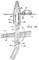
- Fig. 1 b shows the invention in a measurement- while-drilling (MWD) application.
- a bent sub-assembly means 302 in the drillstring provides directional control for the drilling operations.
- Voltage application apparatus is shown in the string and includes battery 24, insulated wireline 305. connected at connections 314 and 315 to upper and lower instrument housings 311 and 312, which house components, such as batteries, sensors and switching apparatus. Voltage or current is applied by electrical contact means 306 and 304 to the drillstring, and then to the formation.
- a borehole drill motor 313 is shown in the string above the drill bit 316. Upper extent of the string is indicated at 22, and the borehole appears at 22 a , in formation 22 b .
- a circuitry housing appears at 307. Surface equipment appears at 22 c .
- Figs. 2 a , 2 b and 2 c illustrate three possible configurations of the system used as a means of downhole electric-field telemetry.
- a voltage is impressed across an insulated drill collar 1, between upper and lower steel drillstring sections 4 and 5, and drives an electric current through the earth 2.
- a power source 3 is connected across an upper section 4 of the drillstring, and a lower section 5 of the drillstring, as by wireline components 6 and a signal source (modulator) indicated as a switch 7, which opens and closes as a function of data to be transmitted, as via a path defined by the drillstring 4 and 5, and the formation 2.
- Sections 4 and 5 are typically metallic (steel), and collar 1 is in series with 4 and 5.
- Signals are detected at the surface of the earth by a receiver 8, which measures the voltage produced by the downhole transmitter, as between two electrodes associated with 8 at the surface.
- Receiver 8 is in a line 8 a connected between the upper end of the string 4 and 9 a , and a probe 9 into the earth. Note the possible connection 9 b to the steel casing in the borehole.
- one electrode comprises an electrical attachment to the drillstring, and the other electrode 9 is connected directly to the earth.
- the insulating section 1 of the drillstring is positioned above the level of a high resistive layer 10 of the formation through which wireline components extend, thus permitting the transmission of downhole information through an insulating geologic formation.
- the drillstring sections 4 b and 5 a consist of steel. Borehole casing is indicated at 4 a .
- FIG. 2 c multiple metallic sections 4 b , 4 c , 5 a , and 5 c of the drillstring are interconnected by insulated sections or collars 1 and 1 a .
- An electrical line 6 interconnects 4 b and 5 a to provide an impedance match and to extend the effective length of the insulating gap.
- Other elements remain as shown in Fig. 2 b .
- Current flow in the formation appears at 400 and 401.
- An alternate means of telemetry from a downhole location to the surface is implemented by modulating the impedance of the entire assembly as measured from surface connections 9 and 9 a .
- a downhole means for alternately electrically connecting and disconnecting portions of the drillstring is provided by using an appropriately positioned gap or gaps 1 in the drillstring sections electrically connected by insulated wireline components 6 and a switching means 7. In this method, the only electrical power required for this means of downhole telemetry is that required for the operation of the electrical switch, thus eliminating the need for downhole power source 3.
- Fig. 3 shows an electrical circuit equivalent of the drillstring-earth transmission path.
- the Fig. 3 elements are defined as follows:
- voltage difference e 1 --e 2 is maintained by current flow i g across the gap 17 a .
- the voltage across the gap is determined largely by the downhole source voltage at 14, the internal resistance 15 of the source 14 and wireline 16, and the resistance 18 of the fluids (mud) in the annulus surrounding the gap sub-assembly.
- the voltage across the gap drives a current i, into the earth 2.
- This flow of current at the surfaces produces a voltage drop (V 1 ) across the resistance 21 of the earth at the surface.
- the voltage V 1 is measured by the receiver electronics.
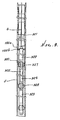
- Fig. 4 Mechanical detail of a two-gap form of the downhole assembly portion of the invention is shown in Fig. 4 .
- the bottom hole assembly is either mounted above a downhole motor 34 or one or more drill collars.
- the upper metallic drillstring section 22 is electrically connected to an upper electrical power source, here represented by a battery 24, as via connection 24 a , housing 23, and centralizer bowed spring 23 a engaging the string bore.
- a drive for the switch 30, in series with line 26, is shown at 30 a .
- the drive is modulated by the output of sensor 33.
- Line 26 electrically connects at 32 to the housing 31, connected to conductive spring 23 b , which electrically engages the bore of lower drillstring section 22 b .
- the sensor sub-assembly may be located above the motor 34, as shown, or in an instrumentation mandrel (bit box) directly above the bit.
- Motor 34 drives (rotates) drill bit 35.
- the invention provides a means for evaluation of resistivity and induced polarization (IP) response at the bit, in the formation surrounding the drillstring or in the formation surrounding a cased borehole.
- IP induced polarization
- a voltage pulse waveform or a set of selected frequencies, is applied across an impedance matched insulated gap or gaps in the drillstring and drill collars configured as shown in Fig. 5 .
- the bulk resistivity of the formation surrounding the insulated gap, drill collar or motor, bit-box, and bit can then be determined by well known data reduction methods for geophysical interpretation of formation resistivity and IP response.
- the resistivity at the bit is analytically separated from the bulk resistivity surrounding the bottom hole assembly by noting that, as the bottom hole assembly passes through a formation and the resistivity is measured, changes in the bulk resistivity will be due to resistivity changes at the bit.
- an upper power and control sub-assembly 36 having one or more current 37 and guard 38 electrodes is mounted on or in and insulated from the drillstring 39.
- This sub-assembly also carries a power source 40 and control and switching electronics 41. See also driver 41 a for switch arm 41.
- An insulated tubular drill collar or gap sub-assembly 42 separates the upper power and control sub-assembly from the motor housing or lower metallic drill collars 43.
- a resistivity-at-bit lower sub-assembly capable of azimuthal measurements is housed by a tubular mandrel 44 extending downwardly from the motor 43.
- This mandrel carries an instrumentation package directly above the bit 45 .
- the instrument package comprises a set of one or more guarded or unguarded current electrodes 46 mounted on and insulated from the mandrel or drill collar; and a means 48 a is provided for connecting lower extent of the wireline 48 to the current electrodes 46 individually, or in combination, at each level.
- Each electrode is shown as surrounded by an insulated guard electrode 47 and associated electronics to provide focusing and to reduce return currents along the motor housing or drill collar. Accordingly, electrical field "lines" can be established at different azimuth locations about the string axis.
- Fig. 5 also represents the combined use of MWD (measure while drilling) technique, together with one of multiple electrodes, as referred to, to measure formation properties. Measured voltage or current values are either interpreted as formation resistivity or IP at control sub-assembly for transmission to the surface by the methods described in the previous paragraph, or the values themselves are transmitted to the surface for interpretation. In this case, the results of formation evaluation are equivalent to sensor output.
- Fig. 6 schematically illustrates this configuration.
- Other similar configurations are possible corresponding to the various electrode configurations developed for (surface) resistivity and IP measurements.
- one or more gap sub-assemblies and wireline system components are used to provide formation resistivity measurements at distances from the borehole previously unobtainable by the prior art.
- a series of insulated, tubular drill collars or gap sub-assemblies 57 , and electrically conducting drill collars or sections of drillstring 58 and 59 are connected in a dipole-dipole configuration, in accordance with known surface geophysics.
- a voltage is applied via source 82 by conductor means 80 and connection means 58a and 58b across conducting sections 58 and 59, which act as effective current electrodes.
- Electric current 84 is thereby driven from the conducting sections into the formation 85 surrounding the borehole 85 a .
- Receiver means 83 is electrically connected to conducting sections 60 and 61 by conductor means 81, and connection means 60a and 60b , and the receiver means detects the potential difference between such conducting sections, which act as effective potential electrodes.
- the electrical resistivity of the formation surrounding the borehole can be determined from such receiver measurements and knowledge of the voltage at source 82.
- the apparatus is configured so as to provide measurement of variable azimuthal resistivity in the formation adjacent to the drillstring.
- a power source at 68 a and suitably driven switching circuits at 67 and 71 drive current along paths 77 into and in the formations, through electrodes 65 and 73, located around the circumference of upper and lower sub-assemblies 64 and 72. mounted between upper and lower sections of the drillstring 63 and 63 a , and connected to the power source by an insulated wireline 70. An insulated, intermediate section of the string appears at 69.
- a downhole motor appears above the drill bit 75 at 76.
- the current flow at electrodes 65 and 73 may be focused by guard electrodes at 74 and 66.
- Switches 67 and 71 operate to azimuthally distribute the voltage application to upper and lower electrodes at different azimuth locations. Such switches are programmably driven, as at 67 a and 71 a .
- Multiple voltage-sensing electrodes are mounted on the circumference of lower sub-assembly 72. Potential differences between various voltage sensors are selected by the upper control sub-assembly via wireline connection 70. In a manner similar to operation of apparatus described and shown in Fig. 5 , azimuthal resistivity values adjacent to the borehole are interpreted and transmitted to the surface.
- the string includes metallic drill pipe, with sections 104 extending from the earth surface downwardly in a borehole 120, to connect at 121 to the upper end of insulative collar 106.
- Metallic drillstring section 105 is connected at 122 to the lower end of collar 106. and extends downwardly toward a drill bit not shown.
- the non-conductive portion of collar 106 may consist of very high-strength composite material, such as KEVLAR, or glass fibers in resin.
- String components 121 and 122 are metallic components of collar 106 having pin and box connection to the drill pipe section, and tapered or conical bonded connections to the non-conductive portion of collar 106 at 126 and 127.
- Drilling fluid typically flows downwardly in the string and through bore 128 in 106; and flows upwardly about the string to carry borehole cuttings to the surface.
- a battery pack (source of voltage) 130 is typically located in hanging sub-assembly 135 above 106, one terminal of the source of voltage in electrical connection with centralizer (belly-type) springs 132 located between the battery pack housings 130 and the bore 133 of 104. An electrical connection is thereby established to the upper string section 104.
- Hanging sub-assembly 135 supports pack 130 in position, as shown, and may be of any suitable form. Note hang support location 135 c .
- Wireline 138 extends downwardly from the battery pack, through the insulating collar 106 to connect to pulser means 140 a in the lower drillstring section. That pulser means is electrically connected to centralizer (belly-type) springs 141 contacting the bore 142 of lower string section 105. Accordingly, the drillstring sections 104 and 105 near the collar 106 act as effective upper and lower electrodes, one to pass current into the formation, and the other to receive current flow back from the formation.
- a second battery pack and housing 140 b supplies power to pulser means 140 a and sensor means 140 c .
- the latter means 140 c produces signals which are encoded by pulser means 140 a .
- a hang support at 140 d carries 140 b .
- a modulator means housed in pressure barrel 320 controls flow of electrical current through wireline 6 to the drillstring 5 by means of an electrical connection from the modulator housing to a pressure barrel 320, and from that pressure barrel to the drillstring by electrically conductive drilling fluids or centralizer means 322.
- Signals from the sensor package, housed in pressure barrel 323, are carried by line or cable means 325 to a multiplexer means housed in barrel 320, and from there to modulator means also housed in barrel 320.
- Power is supplied from source housed in pressure barrel 324 to the sensors by means 328, to the multiplexer and to the modulator by means 327.
- the entire assembly is supported by hanging sub-assembly 135 a carried by the string, and constrained from rotation by means 135 b .
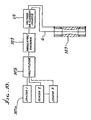
- the transceiver/sensor package is shown in its functional relation to the drillstring in Fig. 10 .
- An insulated wireline 6 is connected from one terminal of a source of voltage or current 24 to the conductive string section at the lower end of a resistive section of the drillstring shown schematically at 303.
- the other terminal of said source is connected to the conductive string section at the upper end of said resistive section.
- a means 309 for modulating or reversing polarity of the source 24 in response to the output of sensors 307 a is provided.
- the multiple sensor outputs 1 through "n" are combined by a multiplexer 307 b before input to the modulator 309.
- the apparatus may also be configured in a manner such that the wellbore casing enhances the conductive path for transmitted currents to the surface.
- an insulating section is provided in the wellbore casing, as shown in Fig. 11 .
- Insulating section 350 confines the flow of electrical currents from the section of drillstring 351 above the transmitting gap to the wellbore casing 352 above the insulating section 350, thereby increasing the current flow 353 between receiver electrodes 9 and 9 a proximate the surface. Note connection of surface line 8 a to the casing at 9 b .
- Non-conducting sub-assemblies may be connected in series, or parallel, or any combination thereof, by use of switching sub-assemblies, as shown in Fig. 12 .
- a power source 401 is connected in either positive or negative polarity by switching means 402 to a pair of conductors 403 and 404 insulated from the drillstring and drilling fluids by tubular sheaths 405 and 406. These conductors may be comprised of specially designed insulated wireline components.
- the drillstring is comprised of multiple, non-conducting sub-assemblies 407 and 409, which are series separated by one or more electrically conducting drillstring components 408 and 410.
- Connector elements 411 and housing 412 are provided, whereby the conductors are connected to connector elements which connect 413 to electrically conducting drillstring elements 408.
- the non-conducting sub-assemblies are connected in series, parallel or any combination thereof with the power source.
- a modulator 414 is deployed in the bottom hole assembly 415 so as to modulate the flow of electric current in the aforementioned circuit for the purpose of transmission of signals derived from one or more sensors 416.
- the string includes drill pipe sections, with sections 104 extending from the earth surface in a borehole 120, to connect at 121 to conductive adapter 435 at the upper end of insulating portion 432 of a non-conductive collar.
- the gap sub-assembly may be provided with a resistive element 431 providing a leakage path for wireline communication with the bottom hole assembly.
- the resistive element 431 is embedded in the insulative material 432 of the gap sub-assembly and electrically connected to upper 435 and lower 436 conductive fittings at 433 and 434, respectively.
- Communication from the surface to the sensor and modulator electronics is accomplished by a communications path employing wireline means 437 connected through upper battery pack 439, to insulated wireline 440, to downhole modulator and sensor electronics 442.
- the insulated wireline components are replaced by a conductor 440 within an insulating tubular sheath 441, as shown in Fig. 12 .
- Pressure changes or flow of drilling fluid may be encoded for communication from the surface to downhole components of the invention.
- Fig. 14 shows the use of a pressure switch 701 for this purpose. Changes in pressure or flow rate of drilling fluid 702 internal to drillstring 703 is sensed by pressure switch means 701, which in turn provides input signals to control means 704.
- Control means 704 is used to control operation of downhole instrumentation, including modulator means 705, power source 706, and sensor means 707. Typically changes in the drilling fluid flow rate, controlled from the surface, can be used to conserve downhole power consumption by the means of the invention.
- multiple receiver electrodes 501, 502, 503, 504, and 505 are deployed as shown in Fig. 15 .
- Some of the electrodes may be effected by direct connections 501 a and 505 a , to the active drillstring or casing 501, or adjacent well casings 505 .
- a switching means 506 and comparator means 507 electrode signals are combined in a manner which provides the best signal reception from a downhole transmitter.
- the switching and comparator means may also be used to provide information on lateral changes in geologic formation, such as the change in resistivity from formation 508 to formation 509.
- the invention improves methods of downhole target detection, location, and tracking while drilling as by means shown in Fig. 16 .
- a time-varying current 521 is injected along the drillstring and into the formation surrounding the drillstring by transmitter means 522.
- Target casing 523 provides an electrically conductive path in the formation for currents 521 .
- current is concentrated, 524, on target casing 523.
- Current flow 524 results in a time varying magnetic field 525, which is measured by magnetetometer means 526.
- Time varying magnetic fields 525, measured by means 526 in the bottom hole assembly bears a known relation to the position of target casing 523. Such measurements arc transmitted to the surface for reception by receiver means 9 and calculation of target position by surface means 528.
- the invention also incorporates several additional improvements over the prior art. These are:
Landscapes
- Engineering & Computer Science (AREA)
- Physics & Mathematics (AREA)
- Life Sciences & Earth Sciences (AREA)
- Geology (AREA)
- Remote Sensing (AREA)
- Geophysics (AREA)
- General Life Sciences & Earth Sciences (AREA)
- Environmental & Geological Engineering (AREA)
- Mining & Mineral Resources (AREA)
- General Physics & Mathematics (AREA)
- Electromagnetism (AREA)
- Fluid Mechanics (AREA)
- Geochemistry & Mineralogy (AREA)
- Geophysics And Detection Of Objects (AREA)
- Arrangements For Transmission Of Measured Signals (AREA)
- Burglar Alarm Systems (AREA)
- Supply And Distribution Of Alternating Current (AREA)
Claims (9)
- Appareil pour la télémétrie à champ électrique de trous de forage comprenant
un train de tuyaux ayant plusieurs sections électriquement conductrices (22, 302),
au moins un collier électriquement isolé (303) connecté entre lesdites sections de tuyaux électriquement conductrices,
une source de courant ou de tension modulée comprenant un moyen de production d'impulsions électriques, et
un système incluant un logement d'instruments dans ledit train de tuyaux et des composants de câblages isolés (305) fournissant des connexions électriques supérieure et inférieure (306, 304) pour transmettre ladite tension ou courant à des sections électriquement conductrices du train de tuyaux séparé par ledit collier isolé,
caractérisé par
ledit logement d'instruments comprenant des logements d'instruments supérieur et inférieur (311, 312) associés auxdites connexions électriques, lesdits logements connectés par lesdits composants de câblages isolés (305) et soutenus dans le train de tuyaux, le logement supérieur (311) au-dessus d'au moins l'un desdits colliers isolants (303), et le logement inférieur (312) en-dessous dudit un collier isolant, ledit moyen de production d'impulsions situé dans au moins l'un desdits logements. - Appareil de la revendication 1, caractérisé par de nombreuses électrodes de potentiel électrique de surface (9) connectées de manière sélective à une unité de commande centrale (8) pour réaliser effectivement le rejet d'un mode commun et d'un bruit local, il existe un moyen pour déplacer effectivement le positionnement de plusieurs desdites électrodes de surface par rapport à la formation souterraine de manière à améliorer l'identification de caractéristiques de formation souterraine, une ou plusieurs desdites électrodes de surface comprenant au moins l'un de ce qui suit:i) le train de tuyaux sous forme d'un train de tiges de forage actifii) un tubage de puits avoisinantiii) le train de tuyaux sous forme d'un tubage de puits actif.
- Appareil de la revendication 2, caractérisé en ce que lesdits logements d'instruments (311, 312) contiennent un ensemble de circuits électronique commandé par ladite transmission de signaux descendante.
- Appareil de la revendication 3, caractérisé en ce que ledit ensemble de circuits inclut des connexions électriques (24a, 32) au tubage d'un puits, lesdites connexions électriques étant en partie situées dans lesdits logements (23, 31).
- Appareil de l'une quelconque des revendications précédentes, caractérisé en ce que le train de tuyaux inclut de nombreux colliers électriquement isolés (1, 1a).
- Appareil de l'une quelconque des revendications précédentes, caractérisé en ce qu'un moyen de mesure est pourvu de sorte qu'une résistivité de formation et/ou une polarisation induite à la fois à un trépan porté par le train de tuyaux et/ou entourant le trou de forage soient mesurées de manière concomitante avec des transmissions de télémétrie de trou de forage, incluant un codage d'information de signaux dérivée d'au moins un capteur de champ électrique porté par le train.
- Appareil de l'une quelconque des revendications précédentes, caractérisé en ce qu'un moyen générateur d'impulsions (140a) est pourvu en association avec l'un desdits logements supérieur et inférieur (311, 312) de sorte qu'une information dérivée d'un ou de plusieurs capteurs portés par le train de tuyaux dans une relation espacée auxdites connexions électriques (304, 306) soit codée par ledit moyen générateur d'impulsions (140a) et transmise à la surface.
- Appareil de l'une quelconque des revendications précédentes, caractérisé par un moyen pour produire une inversion de polarité d'impulsions.
- Appareil de l'une quelconque des revendications précédentes, caractérisé en ce que ledit moyen de production d'impulsions produit des formes d'onde d'impulsions d'une durée de moins de 200 ms.
Applications Claiming Priority (5)
| Application Number | Priority Date | Filing Date | Title |
|---|---|---|---|
| US2479496P | 1996-07-31 | 1996-07-31 | |
| US24794P | 1996-07-31 | ||
| US08/707,270 US5883516A (en) | 1996-07-31 | 1996-09-03 | Apparatus and method for electric field telemetry employing component upper and lower housings in a well pipestring |
| US707270 | 1996-09-03 | ||
| PCT/US1997/012829 WO1998006924A2 (fr) | 1996-07-31 | 1997-07-22 | Procede et appareil de telemetrie a champ electrique et d'evaluation de formation combinees |
Publications (3)
| Publication Number | Publication Date |
|---|---|
| EP0916101A2 EP0916101A2 (fr) | 1999-05-19 |
| EP0916101A4 EP0916101A4 (fr) | 2002-04-03 |
| EP0916101B1 true EP0916101B1 (fr) | 2008-04-23 |
Family
ID=26698877
Family Applications (1)
| Application Number | Title | Priority Date | Filing Date |
|---|---|---|---|
| EP97935059A Expired - Lifetime EP0916101B1 (fr) | 1996-07-31 | 1997-07-22 | Appareil combinant la telemetrie a champ electrique et l'evaluation de formation |
Country Status (6)
| Country | Link |
|---|---|
| US (1) | US5883516A (fr) |
| EP (1) | EP0916101B1 (fr) |
| AU (1) | AU723778B2 (fr) |
| CA (1) | CA2261686C (fr) |
| DE (1) | DE69738650D1 (fr) |
| WO (1) | WO1998006924A2 (fr) |
Cited By (2)
| Publication number | Priority date | Publication date | Assignee | Title |
|---|---|---|---|---|
| US9863239B2 (en) | 2014-06-19 | 2018-01-09 | Evolution Engineering Inc. | Selecting transmission frequency based on formation properties |
| US9976415B2 (en) | 2015-05-27 | 2018-05-22 | Evolution Engineering Inc. | Electromagnetic telemetry system with compensation for drilling fluid characteristics |
Families Citing this family (91)
| Publication number | Priority date | Publication date | Assignee | Title |
|---|---|---|---|---|
| US6710600B1 (en) | 1994-08-01 | 2004-03-23 | Baker Hughes Incorporated | Drillpipe structures to accommodate downhole testing |
| CA2151525C (fr) | 1995-06-12 | 2002-12-31 | Marvin L. Holbert | Appareil de transmission de signaux souterrains |
| US7252160B2 (en) | 1995-06-12 | 2007-08-07 | Weatherford/Lamb, Inc. | Electromagnetic gap sub assembly |
| US6396276B1 (en) * | 1996-07-31 | 2002-05-28 | Scientific Drilling International | Apparatus and method for electric field telemetry employing component upper and lower housings in a well pipestring |
| US6188222B1 (en) * | 1997-09-19 | 2001-02-13 | Schlumberger Technology Corporation | Method and apparatus for measuring resistivity of an earth formation |
| US6114972A (en) * | 1998-01-20 | 2000-09-05 | Halliburton Energy Services, Inc. | Electromagnetic resistivity tool and method for use of same |
| US6367565B1 (en) * | 1998-03-27 | 2002-04-09 | David R. Hall | Means for detecting subterranean formations and monitoring the operation of a down-hole fluid driven percussive piston |
| CA2272044C (fr) * | 1998-05-18 | 2005-10-25 | Denis S. Kopecki | Structures de tiges de forage adaptees aux essais de production en puits |
| GB2344127B (en) * | 1998-05-18 | 2000-12-06 | Baker Hughes Inc | Drillpipe structures to accomodate downhole testing |
| GB9818418D0 (en) * | 1998-08-26 | 1998-10-21 | Dailey Ids Limited | Sub |
| FR2785017B1 (fr) * | 1998-10-23 | 2000-12-22 | Geoservices | Methode et systeme de transmission d'informations par onde electromagnetique |
| EP1166476B1 (fr) * | 1999-04-08 | 2006-07-19 | Honeywell International Inc. | Procede et systeme communiquant des donnees avec un bloc d'instruments souterrains |
| US7071837B2 (en) * | 1999-07-07 | 2006-07-04 | Expro North Sea Limited | Data transmission in pipeline systems |
| CA2380300C (fr) * | 1999-10-29 | 2004-07-20 | Halliburton Energy Services, Inc. | Ensemble et procede de prolongement d'antenne electromagnetique |
| US6679332B2 (en) | 2000-01-24 | 2004-01-20 | Shell Oil Company | Petroleum well having downhole sensors, communication and power |
| US6817412B2 (en) * | 2000-01-24 | 2004-11-16 | Shell Oil Company | Method and apparatus for the optimal predistortion of an electromagnetic signal in a downhole communication system |
| US6715550B2 (en) | 2000-01-24 | 2004-04-06 | Shell Oil Company | Controllable gas-lift well and valve |
| US6758277B2 (en) | 2000-01-24 | 2004-07-06 | Shell Oil Company | System and method for fluid flow optimization |
| AU772610B2 (en) | 2000-01-24 | 2004-05-06 | Shell Internationale Research Maatschappij B.V. | Downhole wireless two-way telemetry system |
| US7259688B2 (en) * | 2000-01-24 | 2007-08-21 | Shell Oil Company | Wireless reservoir production control |
| US7114561B2 (en) | 2000-01-24 | 2006-10-03 | Shell Oil Company | Wireless communication using well casing |
| US6840316B2 (en) | 2000-01-24 | 2005-01-11 | Shell Oil Company | Tracker injection in a production well |
| US20020036085A1 (en) * | 2000-01-24 | 2002-03-28 | Bass Ronald Marshall | Toroidal choke inductor for wireless communication and control |
| US6633236B2 (en) | 2000-01-24 | 2003-10-14 | Shell Oil Company | Permanent downhole, wireless, two-way telemetry backbone using redundant repeaters |
| US6662875B2 (en) | 2000-01-24 | 2003-12-16 | Shell Oil Company | Induction choke for power distribution in piping structure |
| US6633164B2 (en) | 2000-01-24 | 2003-10-14 | Shell Oil Company | Measuring focused through-casing resistivity using induction chokes and also using well casing as the formation contact electrodes |
| EG22206A (en) | 2000-03-02 | 2002-10-31 | Shell Int Research | Oilwell casing electrical power pick-off points |
| CA2401705C (fr) | 2000-03-02 | 2013-09-24 | Shell Canada Limited | Mesure et commande sans fil en fond de trou permettant d'optimiser la performance d'un champ et d'un puits a extraction au gaz |
| CA2401723C (fr) | 2000-03-02 | 2009-06-09 | Shell Canada Limited | Tubage de revetement de puits utilisant la communication sans fil |
| CA2401707C (fr) | 2000-03-02 | 2009-11-03 | Shell Canada Limited | Actionneur electro-hydraulique sous pression pour vanne de fonds de puits |
| BR0108881B1 (pt) * | 2000-03-02 | 2010-10-05 | sistema de injeção de substáncia quìmica para uso em um poço, poço de petróleo para produção de produtos de petróleo, e método de operar um poço de petróleo. | |
| RU2258800C2 (ru) * | 2000-03-02 | 2005-08-20 | Шелл Интернэшнл Рисерч Маатсхаппий Б.В. | Нефтяная скважина (варианты), способ ее работы, система и способ подачи питания скважинного устройства |
| US7170424B2 (en) * | 2000-03-02 | 2007-01-30 | Shell Oil Company | Oil well casting electrical power pick-off points |
| US7073594B2 (en) | 2000-03-02 | 2006-07-11 | Shell Oil Company | Wireless downhole well interval inflow and injection control |
| MY128294A (en) | 2000-03-02 | 2007-01-31 | Shell Int Research | Use of downhole high pressure gas in a gas-lift well |
| DE60123759T2 (de) | 2000-03-02 | 2007-10-11 | Shell Internationale Research Maatschappij B.V. | Drahtlos-kreuzschienenschalter zur leistungs- und datenverteilung |
| FR2806799B1 (fr) * | 2000-03-22 | 2002-06-21 | Schlumberger Services Petrol | Dispositifs de caracterisation d'un fluide polyphasique a phase conductrice continue |
| US7071697B2 (en) * | 2001-01-04 | 2006-07-04 | Schlumberger Technology Corporation | Centralizer including measurement means |
| US7322410B2 (en) * | 2001-03-02 | 2008-01-29 | Shell Oil Company | Controllable production well packer |
| GB0116120D0 (en) * | 2001-06-30 | 2001-08-22 | Maxwell Downhole Technology Lt | Insulating device and assembly |
| US6839000B2 (en) | 2001-10-29 | 2005-01-04 | Baker Hughes Incorporated | Integrated, single collar measurement while drilling tool |
| GB0211137D0 (en) * | 2002-05-15 | 2002-06-26 | Flight Refueling Ltd | Joint detection |
| US7080699B2 (en) * | 2004-01-29 | 2006-07-25 | Schlumberger Technology Corporation | Wellbore communication system |
| US6995683B2 (en) * | 2004-03-12 | 2006-02-07 | Welldynamics, Inc. | System and method for transmitting downhole data to the surface |
| US7493962B2 (en) * | 2004-12-14 | 2009-02-24 | Schlumberger Technology Corporation | Control line telemetry |
| US7518528B2 (en) * | 2005-02-28 | 2009-04-14 | Scientific Drilling International, Inc. | Electric field communication for short range data transmission in a borehole |
| ES2339361T3 (es) | 2005-07-29 | 2010-05-19 | Prad Research And Development Limited | Metodo y aparato para transmitir o recibir informacion entre un equipo de fondo de pozo y la superficie. |
| US7913773B2 (en) * | 2005-08-04 | 2011-03-29 | Schlumberger Technology Corporation | Bidirectional drill string telemetry for measuring and drilling control |
| US7812610B2 (en) * | 2005-11-04 | 2010-10-12 | Schlumberger Technology Corporation | Method and apparatus for locating well casings from an adjacent wellbore |
| US7554329B2 (en) * | 2006-04-07 | 2009-06-30 | Baker Hughes Incorporated | Method and apparatus for determining formation resistivity ahead of the bit and azimuthal at the bit |
| CA2544457C (fr) | 2006-04-21 | 2009-07-07 | Mostar Directional Technologies Inc. | Systeme et methode de telemesure de fond de trou |
| US20080034856A1 (en) * | 2006-08-08 | 2008-02-14 | Scientific Drilling International | Reduced-length measure while drilling apparatus using electric field short range data transmission |
| US8044819B1 (en) | 2006-10-23 | 2011-10-25 | Scientific Drilling International | Coal boundary detection using an electric-field borehole telemetry apparatus |
| US7782060B2 (en) * | 2006-12-28 | 2010-08-24 | Schlumberger Technology Corporation | Integrated electrode resistivity and EM telemetry tool |
| WO2008118931A2 (fr) * | 2007-03-27 | 2008-10-02 | Shell Oil Company | Communication à l'intérieur d'un puits, module de fond de trou, et méthode de communication |
| US7598683B1 (en) | 2007-07-31 | 2009-10-06 | Lsi Industries, Inc. | Control of light intensity using pulses of a fixed duration and frequency |
| US8604709B2 (en) | 2007-07-31 | 2013-12-10 | Lsi Industries, Inc. | Methods and systems for controlling electrical power to DC loads |
| US8903577B2 (en) | 2009-10-30 | 2014-12-02 | Lsi Industries, Inc. | Traction system for electrically powered vehicles |
| US20090066334A1 (en) * | 2007-09-10 | 2009-03-12 | Baker Hughes Incorporated | Short Normal Electrical Measurement Using an EM-Transmitter |
| WO2009042494A2 (fr) * | 2007-09-27 | 2009-04-02 | Schlumberger Canada Limited | Source d'alimentation modulaire pour des systèmes de subsurface |
| CN101827997B (zh) * | 2007-10-17 | 2014-11-05 | 普拉德研究及开发股份有限公司 | 用于井眼工具的电接触连接 |
| US8284073B2 (en) * | 2008-04-17 | 2012-10-09 | Schlumberger Technology Corporation | Downlink while pumps are off |
| CN102239430B (zh) | 2008-12-03 | 2015-09-02 | 哈里伯顿能源服务公司 | 跨间隙的信号传播 |
| US8322462B2 (en) | 2008-12-22 | 2012-12-04 | Halliburton Energy Services, Inc. | Proximity detection system for deep wells |
| US8069931B2 (en) * | 2009-04-09 | 2011-12-06 | Phoenix Technology Services Lp | System, method and apparatus for downhole system having integrated measurement while operating components |
| CA2795482C (fr) * | 2009-04-23 | 2014-07-08 | Schlumberger Canada Limited | Ensemble trepan ayant un joint ouvert isole electriquement pour telemetrie electromagnetique |
| US8633701B2 (en) * | 2009-07-30 | 2014-01-21 | Baker Hughes Incorporated | Method and apparatus for galvanic multi-frequency formation resistivity imaging |
| CA2736398A1 (fr) | 2009-08-17 | 2011-02-24 | Magnum Drilling Services, Inc. | Dispositifs de mesure d'inclinaison et procedes d'utilisation |
| US8881414B2 (en) | 2009-08-17 | 2014-11-11 | Magnum Drilling Services, Inc. | Inclination measurement devices and methods of use |
| US9500762B2 (en) * | 2011-09-19 | 2016-11-22 | Precision Energy Services, Inc. | Borehole resistivity imager using discrete energy pulsing |
| WO2014052197A1 (fr) * | 2012-09-26 | 2014-04-03 | Nabors International, Inc. | Télémétrie de données électromagnétiques pour le forage de puits de fond de trou |
| US9909369B2 (en) | 2012-11-16 | 2018-03-06 | Evolution Engineering Inc. | Electromagnetic telemetry gap sub assembly with insulating collar |
| WO2014131133A1 (fr) | 2013-03-01 | 2014-09-04 | Evolution Engineering Inc. | Sous-ensemble isolant électromagnétique à goupille de télémétrie |
| WO2014201572A1 (fr) | 2013-06-21 | 2014-12-24 | Evolution Engineering Inc. | Procédés et appareils pour générer des signaux de télémétrie électromagnétiques |
| MX2016002893A (es) * | 2013-09-05 | 2016-12-20 | Evolution Engineering Inc | Transmision de datos a través de espacios aislantes de la electricidad en una sarta de perforación. |
| CN105874163B (zh) * | 2013-09-30 | 2019-12-31 | 信远达石油服务有限公司 | 钻井辅助系统 |
| US9359889B2 (en) * | 2013-10-17 | 2016-06-07 | Well Resolutions Technology | System and methods for selective shorting of an electrical insulator section |
| US9638028B2 (en) * | 2014-08-27 | 2017-05-02 | Schlumberger Technology Corporation | Electromagnetic telemetry for measurement and logging while drilling and magnetic ranging between wellbores |
| GB2545596B (en) | 2014-11-12 | 2020-09-23 | Halliburton Energy Services Inc | Well detection using induced magnetic fields |
| US11073013B2 (en) | 2014-12-18 | 2021-07-27 | Schlumberger Technology Corporation | Electric dipole surface antenna configurations for electromagnetic wellbore instrument telemetry |
| WO2016100672A1 (fr) * | 2014-12-18 | 2016-06-23 | Schlumberger Canada Limited | Procédés et systèmes pour renforcer l'intensité d'un signal électromagnétique de télémétrie détecté en surface |
| WO2016167781A1 (fr) * | 2015-04-16 | 2016-10-20 | Halliburton Energy Services, Inc. | Stabilisateur avec électrode montée sur ailette permettant de fournir des signaux à une antenne de train de tiges de forage |
| US9803473B2 (en) | 2015-10-23 | 2017-10-31 | Schlumberger Technology Corporation | Downhole electromagnetic telemetry receiver |
| CA3015993C (fr) * | 2016-05-11 | 2020-08-11 | Halliburton Energy Services, Inc. | Determination de la resistivite d'une formation souterraine au moyen d'un systeme de telemetrie electromagnetique |
| US10968735B2 (en) | 2016-12-28 | 2021-04-06 | Halliburton Energy Services, Inc. | Deviated production well telemetry with assisting well/drillship |
| CA3049959A1 (fr) | 2017-01-13 | 2018-07-19 | Board Of Regents, University Of Texas System | Outil a electrodes modulaires pour diagnostics de fracture hydraulique ameliores |
| US11811273B2 (en) | 2018-06-01 | 2023-11-07 | Franklin Electric Co., Inc. | Motor protection device and method for protecting a motor |
| US10454267B1 (en) | 2018-06-01 | 2019-10-22 | Franklin Electric Co., Inc. | Motor protection device and method for protecting a motor |
| CN109653735B (zh) * | 2019-03-01 | 2022-11-15 | 西南石油大学 | 一种基于电流回路的钻井信号下传装置及信号下传方法 |
| CN111396035B (zh) * | 2020-03-04 | 2020-11-27 | 中国地质大学(武汉) | 基于电磁随钻测量信号识别煤层与围岩界面及电阻率方法 |
| CA3192218C (fr) * | 2020-09-11 | 2023-08-15 | Scientific Drilling International, Inc. | Extension d'electrode inferieure pour systeme de telemesure electromagnetique de subsurface |
Family Cites Families (62)
| Publication number | Priority date | Publication date | Assignee | Title |
|---|---|---|---|---|
| US2364957A (en) * | 1939-08-08 | 1944-12-12 | Stanolind Oil & Gas Co | Electrical surveying |
| US2400170A (en) * | 1942-08-29 | 1946-05-14 | Stanolind Oil & Gas Co | Time cycle telemetering |
| US2389241A (en) * | 1944-04-26 | 1945-11-20 | Stanolind Oil & Gas Co | Well logging |
| US2650067A (en) * | 1948-12-13 | 1953-08-25 | Philip W Martin | Apparatus for logging wells while drilling |
| US2681567A (en) * | 1949-12-29 | 1954-06-22 | Stanolind Oil & Gas Co | System for obtaining and transmitting measurements in wells during drilling |
| US2941784A (en) * | 1955-07-05 | 1960-06-21 | Atlantic Refining Co | Logging while drilling |
| US2924432A (en) * | 1956-05-08 | 1960-02-09 | Jan J Arps | Earth borehole logging system |
| US3046474A (en) * | 1957-07-03 | 1962-07-24 | Arps Corp | Bore-hole logging system and method |
| US2938708A (en) * | 1957-09-19 | 1960-05-31 | Jan J Arps | Simultaneous drilling and electrical logging of hydrocarbon contents of formations |
| US3302457A (en) * | 1964-06-02 | 1967-02-07 | Sun Oil Co | Method and apparatus for telemetering in a bore hole by changing drilling mud pressure |
| US3309656A (en) * | 1964-06-10 | 1967-03-14 | Mobil Oil Corp | Logging-while-drilling system |
| US3517553A (en) * | 1967-12-06 | 1970-06-30 | Tenneco Oil Co | Method and apparatus for measuring and controlling bottomhole differential pressure while drilling |
| FR2109035A5 (fr) * | 1970-05-11 | 1972-05-26 | Aquitaine Petrole | |
| US3736558A (en) * | 1970-07-30 | 1973-05-29 | Schlumberger Technology Corp | Data-signaling apparatus for well drilling tools |
| US3711825A (en) * | 1970-07-30 | 1973-01-16 | Schlumberger Technology Corp | Data-signaling apparatus for well drilling tools |
| CA953785A (en) * | 1971-03-09 | 1974-08-27 | Rudolf J. Rammner | Apparatus for transmitting data from a hole drilled in the earth |
| DE2416063C3 (de) * | 1974-04-03 | 1978-03-30 | Erich 3000 Hannover Krebs | Vorrichtung zum Messen und drahtlosen Übertragen von Meßwerten zur Erdoberfläche |
| US3958217A (en) * | 1974-05-10 | 1976-05-18 | Teleco Inc. | Pilot operated mud-pulse valve |
| US4078620A (en) * | 1975-03-10 | 1978-03-14 | Westlake John H | Method of and apparatus for telemetering information from a point in a well borehole to the earth's surface |
| US4057781A (en) * | 1976-03-19 | 1977-11-08 | Scherbatskoy Serge Alexander | Well bore communication method |
| US4072200A (en) * | 1976-05-12 | 1978-02-07 | Morris Fred J | Surveying of subterranean magnetic bodies from an adjacent off-vertical borehole |
| US4130169A (en) * | 1977-04-22 | 1978-12-19 | Shell Oil Company | Downhole connector for use with drill string telemetering system |
| US4160970A (en) * | 1977-11-25 | 1979-07-10 | Sperry Rand Corporation | Electromagnetic wave telemetry system for transmitting downhole parameters to locations thereabove |
| US4351037A (en) * | 1977-12-05 | 1982-09-21 | Scherbatskoy Serge Alexander | Systems, apparatus and methods for measuring while drilling |
| US5390153A (en) * | 1977-12-05 | 1995-02-14 | Scherbatskoy; Serge A. | Measuring while drilling employing cascaded transmission systems |
| US4181014A (en) * | 1978-05-04 | 1980-01-01 | Scientific Drilling Controls, Inc. | Remote well signalling apparatus and methods |
| US4262343A (en) * | 1979-04-18 | 1981-04-14 | Dresser Industries | Pressure pulse detection apparatus |
| DE3035905C2 (de) * | 1980-09-24 | 1982-12-30 | Christensen, Inc., 84115 Salt Lake City, Utah | Vorrichtung zur Fernübertragung von Informationen aus einem Bohrloch zur Erdoberfläche während des Betriebs eines Bohrgeräts |
| US4496174A (en) * | 1981-01-30 | 1985-01-29 | Tele-Drill, Inc. | Insulated drill collar gap sub assembly for a toroidal coupled telemetry system |
| US4774694A (en) * | 1981-12-15 | 1988-09-27 | Scientific Drilling International | Well information telemetry by variation of mud flow rate |
| US4699352A (en) * | 1982-03-08 | 1987-10-13 | Exploration Logging, Inc. | Apparatus for well logging telemetry |
| US4578675A (en) * | 1982-09-30 | 1986-03-25 | Macleod Laboratories, Inc. | Apparatus and method for logging wells while drilling |
| FR2545535B1 (fr) * | 1983-05-06 | 1988-04-08 | Geoservices | Dispositif pour transmettre en surface les signaux d'un emetteur situe a grande profondeur |
| FR2562601B2 (fr) * | 1983-05-06 | 1988-05-27 | Geoservices | Dispositif pour transmettre en surface les signaux d'un emetteur situe a grande profondeur |
| US4691203A (en) * | 1983-07-01 | 1987-09-01 | Rubin Llewellyn A | Downhole telemetry apparatus and method |
| US4821035A (en) * | 1984-05-01 | 1989-04-11 | Comdisco Resources, Inc. | Method and apparatus using a well casing for transmitting data up a well |
| US4694439A (en) * | 1985-07-18 | 1987-09-15 | Scientific Drilling International | Well information telemetry by variation of mud flow rate |
| US4715022A (en) * | 1985-08-29 | 1987-12-22 | Scientific Drilling International | Detection means for mud pulse telemetry system |
| FR2600171B1 (fr) * | 1986-06-17 | 1990-10-19 | Geoservices | Antenne pour emetteur situe a grande profondeur |
| US5043668A (en) * | 1987-08-26 | 1991-08-27 | Paramagnetic Logging Inc. | Methods and apparatus for measurement of electronic properties of geological formations through borehole casing |
| US4820989A (en) * | 1986-11-04 | 1989-04-11 | Paramagnetic Logging, Inc. | Methods and apparatus for measurement of the resistivity of geological formations from within cased boreholes |
| FR2617901B1 (fr) * | 1987-07-06 | 1989-10-27 | Alsthom | Procede de forage avec transmission electromagnetique d'informations depuis le fond |
| US5081419A (en) * | 1990-10-09 | 1992-01-14 | Baker Hughes Incorporated | High sensitivity well logging system having dual transmitter antennas and intermediate series resonant |
| US5061849A (en) * | 1988-04-01 | 1991-10-29 | Baker Hughes Incorporated | Externally mounted radioactivity detector for MWD employing radial inline scintillator and photomultiplier tube |
| US5230387A (en) * | 1988-10-28 | 1993-07-27 | Magrange, Inc. | Downhole combination tool |
| FR2646508B1 (fr) * | 1989-04-26 | 1994-04-29 | Geoservices | Procede et appareil pour prelever en continu des echantillons gazeux contenus dans un liquide egalement charge de solides notamment dans une boue de forage petrolier |
| US4980682A (en) * | 1989-07-31 | 1990-12-25 | Atlantic Richfield Company | Method of reducing noise in a borehole electromagnetic telemetry system |
| GB2235296B (en) * | 1989-08-10 | 1994-11-30 | Exploration Logging Inc | Well logging system arranged for stable,high-sensitivity reception of propagating electromagnetic waves |
| US5270703A (en) * | 1990-08-31 | 1993-12-14 | Halliburton Company | Bipolar signal amplification or generation |
| US5189415A (en) * | 1990-11-09 | 1993-02-23 | Japan National Oil Corporation | Receiving apparatus |
| US5138313A (en) * | 1990-11-15 | 1992-08-11 | Halliburton Company | Electrically insulative gap sub assembly for tubular goods |
| US5155916A (en) * | 1991-03-21 | 1992-10-20 | Scientific Drilling International | Error reduction in compensation of drill string interference for magnetic survey tools |
| US5130706A (en) * | 1991-04-22 | 1992-07-14 | Scientific Drilling International | Direct switching modulation for electromagnetic borehole telemetry |
| FR2681461B1 (fr) * | 1991-09-12 | 1993-11-19 | Geoservices | Procede et agencement pour la transmission d'informations, de parametres et de donnees a un organe electro-magnetique de reception ou de commande associe a une canalisation souterraine de grande longueur. |
| US5235285A (en) * | 1991-10-31 | 1993-08-10 | Schlumberger Technology Corporation | Well logging apparatus having toroidal induction antenna for measuring, while drilling, resistivity of earth formations |
| NO306522B1 (no) * | 1992-01-21 | 1999-11-15 | Anadrill Int Sa | Fremgangsmaate for akustisk overföring av maalesignaler ved maaling under boring |
| FR2697119B1 (fr) * | 1992-10-16 | 1995-01-20 | Schlumberger Services Petrol | Dispositif émetteur à double raccord isolant, destiné à l'emploi dans un forage. |
| US5321893A (en) * | 1993-02-26 | 1994-06-21 | Scientific Drilling International | Calibration correction method for magnetic survey tools |
| US5366018A (en) * | 1993-08-16 | 1994-11-22 | Scientific Drilling International | Miniature rope socket assembly for combined mechanical and electrical connection in a borehole wireline |
| US5467083A (en) * | 1993-08-26 | 1995-11-14 | Electric Power Research Institute | Wireless downhole electromagnetic data transmission system and method |
| US5512889A (en) * | 1994-05-24 | 1996-04-30 | Atlantic Richfield Company | Downhole instruments for well operations |
| US5563512A (en) * | 1994-06-14 | 1996-10-08 | Halliburton Company | Well logging apparatus having a removable sleeve for sealing and protecting multiple antenna arrays |
-
1996
- 1996-09-03 US US08/707,270 patent/US5883516A/en not_active Expired - Lifetime
-
1997
- 1997-07-22 EP EP97935059A patent/EP0916101B1/fr not_active Expired - Lifetime
- 1997-07-22 AU AU38088/97A patent/AU723778B2/en not_active Ceased
- 1997-07-22 DE DE69738650T patent/DE69738650D1/de not_active Expired - Lifetime
- 1997-07-22 WO PCT/US1997/012829 patent/WO1998006924A2/fr not_active Ceased
- 1997-07-22 CA CA002261686A patent/CA2261686C/fr not_active Expired - Fee Related
Cited By (2)
| Publication number | Priority date | Publication date | Assignee | Title |
|---|---|---|---|---|
| US9863239B2 (en) | 2014-06-19 | 2018-01-09 | Evolution Engineering Inc. | Selecting transmission frequency based on formation properties |
| US9976415B2 (en) | 2015-05-27 | 2018-05-22 | Evolution Engineering Inc. | Electromagnetic telemetry system with compensation for drilling fluid characteristics |
Also Published As
| Publication number | Publication date |
|---|---|
| AU723778B2 (en) | 2000-09-07 |
| DE69738650D1 (de) | 2008-06-05 |
| WO1998006924A3 (fr) | 1998-03-26 |
| EP0916101A2 (fr) | 1999-05-19 |
| AU3808897A (en) | 1998-03-06 |
| CA2261686A1 (fr) | 1998-02-19 |
| EP0916101A4 (fr) | 2002-04-03 |
| US5883516A (en) | 1999-03-16 |
| WO1998006924A2 (fr) | 1998-02-19 |
| CA2261686C (fr) | 2006-02-21 |
Similar Documents
| Publication | Publication Date | Title |
|---|---|---|
| EP0916101B1 (fr) | Appareil combinant la telemetrie a champ electrique et l'evaluation de formation | |
| US6188223B1 (en) | Electric field borehole telemetry | |
| US6396276B1 (en) | Apparatus and method for electric field telemetry employing component upper and lower housings in a well pipestring | |
| US7126492B2 (en) | Electromagnetic borehole telemetry system incorporating a conductive borehole tubular | |
| AU2018206790B2 (en) | Transmitting data across electrically insulating gaps in a drill string | |
| CA2959346C (fr) | Telemetrie electromagnetique pour la mesure et la diagraphie en cours de forage et la telemetrie magnetique entre des puits de forage | |
| US6469635B1 (en) | Bore hole transmission system using impedance modulation | |
| US10830036B2 (en) | Well monitoring using casing centralizers | |
| EP0987401A2 (fr) | Télémétrie pour train de tiges de forage | |
| MX2010010963A (es) | Metodo y sistema de transmision de ondas electromagneticas desde un barreno de pozo. | |
| WO2009035978A1 (fr) | Mesure électrique normale courte au moyen d'un émetteur de signaux électro-magnétiques | |
| US20140000910A1 (en) | Apparatus with rigid support and related methods | |
| CN103835705A (zh) | 井下测量信息传输系统 | |
| US20250369350A1 (en) | Method and Apparatus For Deep Electromagnetic Communication |
Legal Events
| Date | Code | Title | Description |
|---|---|---|---|
| PUAI | Public reference made under article 153(3) epc to a published international application that has entered the european phase |
Free format text: ORIGINAL CODE: 0009012 |
|
| 17P | Request for examination filed |
Effective date: 19990204 |
|
| AK | Designated contracting states |
Kind code of ref document: A2 Designated state(s): BE DE DK FR GB IT NL |
|
| RIC1 | Information provided on ipc code assigned before grant |
Free format text: 7G 01V 3/02 A, 7E 21B 47/12 B |
|
| A4 | Supplementary search report drawn up and despatched |
Effective date: 20020213 |
|
| AK | Designated contracting states |
Kind code of ref document: A4 Designated state(s): BE DE DK FR GB IT NL |
|
| 17Q | First examination report despatched |
Effective date: 20041202 |
|
| RTI1 | Title (correction) |
Free format text: COMBINED ELECTRIC-FIELD TELEMETRY AND FORMATION EVALUATION APPARATUS |
|
| GRAP | Despatch of communication of intention to grant a patent |
Free format text: ORIGINAL CODE: EPIDOSNIGR1 |
|
| GRAS | Grant fee paid |
Free format text: ORIGINAL CODE: EPIDOSNIGR3 |
|
| GRAA | (expected) grant |
Free format text: ORIGINAL CODE: 0009210 |
|
| AK | Designated contracting states |
Kind code of ref document: B1 Designated state(s): BE DE DK FR GB IT NL |
|
| REG | Reference to a national code |
Ref country code: GB Ref legal event code: FG4D |
|
| REF | Corresponds to: |
Ref document number: 69738650 Country of ref document: DE Date of ref document: 20080605 Kind code of ref document: P |
|
| NLV1 | Nl: lapsed or annulled due to failure to fulfill the requirements of art. 29p and 29m of the patents act | ||
| PG25 | Lapsed in a contracting state [announced via postgrant information from national office to epo] |
Ref country code: NL Free format text: LAPSE BECAUSE OF FAILURE TO SUBMIT A TRANSLATION OF THE DESCRIPTION OR TO PAY THE FEE WITHIN THE PRESCRIBED TIME-LIMIT Effective date: 20080423 |
|
| PG25 | Lapsed in a contracting state [announced via postgrant information from national office to epo] |
Ref country code: DK Free format text: LAPSE BECAUSE OF FAILURE TO SUBMIT A TRANSLATION OF THE DESCRIPTION OR TO PAY THE FEE WITHIN THE PRESCRIBED TIME-LIMIT Effective date: 20080423 |
|
| EN | Fr: translation not filed | ||
| PG25 | Lapsed in a contracting state [announced via postgrant information from national office to epo] |
Ref country code: BE Free format text: LAPSE BECAUSE OF FAILURE TO SUBMIT A TRANSLATION OF THE DESCRIPTION OR TO PAY THE FEE WITHIN THE PRESCRIBED TIME-LIMIT Effective date: 20080423 |
|
| PLBE | No opposition filed within time limit |
Free format text: ORIGINAL CODE: 0009261 |
|
| STAA | Information on the status of an ep patent application or granted ep patent |
Free format text: STATUS: NO OPPOSITION FILED WITHIN TIME LIMIT |
|
| 26N | No opposition filed |
Effective date: 20090126 |
|
| PG25 | Lapsed in a contracting state [announced via postgrant information from national office to epo] |
Ref country code: DE Free format text: LAPSE BECAUSE OF FAILURE TO SUBMIT A TRANSLATION OF THE DESCRIPTION OR TO PAY THE FEE WITHIN THE PRESCRIBED TIME-LIMIT Effective date: 20080724 |
|
| PG25 | Lapsed in a contracting state [announced via postgrant information from national office to epo] |
Ref country code: IT Free format text: LAPSE BECAUSE OF FAILURE TO SUBMIT A TRANSLATION OF THE DESCRIPTION OR TO PAY THE FEE WITHIN THE PRESCRIBED TIME-LIMIT Effective date: 20080423 |
|
| PG25 | Lapsed in a contracting state [announced via postgrant information from national office to epo] |
Ref country code: FR Free format text: LAPSE BECAUSE OF FAILURE TO SUBMIT A TRANSLATION OF THE DESCRIPTION OR TO PAY THE FEE WITHIN THE PRESCRIBED TIME-LIMIT Effective date: 20090227 |
|
| PGFP | Annual fee paid to national office [announced via postgrant information from national office to epo] |
Ref country code: GB Payment date: 20140723 Year of fee payment: 18 |
|
| GBPC | Gb: european patent ceased through non-payment of renewal fee |
Effective date: 20150722 |
|
| PG25 | Lapsed in a contracting state [announced via postgrant information from national office to epo] |
Ref country code: GB Free format text: LAPSE BECAUSE OF NON-PAYMENT OF DUE FEES Effective date: 20150722 |