EP0916243A1 - Dispositif de travail pour travail visé à travers d'une rangée - Google Patents
Dispositif de travail pour travail visé à travers d'une rangée Download PDFInfo
- Publication number
- EP0916243A1 EP0916243A1 EP98121348A EP98121348A EP0916243A1 EP 0916243 A1 EP0916243 A1 EP 0916243A1 EP 98121348 A EP98121348 A EP 98121348A EP 98121348 A EP98121348 A EP 98121348A EP 0916243 A1 EP0916243 A1 EP 0916243A1
- Authority
- EP
- European Patent Office
- Prior art keywords
- tool
- rotor
- row
- machining
- rotation
- Prior art date
- Legal status (The legal status is an assumption and is not a legal conclusion. Google has not performed a legal analysis and makes no representation as to the accuracy of the status listed.)
- Withdrawn
Links
Images




Classifications
-
- A—HUMAN NECESSITIES
- A01—AGRICULTURE; FORESTRY; ANIMAL HUSBANDRY; HUNTING; TRAPPING; FISHING
- A01B—SOIL WORKING IN AGRICULTURE OR FORESTRY; PARTS, DETAILS, OR ACCESSORIES OF AGRICULTURAL MACHINES OR IMPLEMENTS, IN GENERAL
- A01B39/00—Machines specially adapted for working soil on which crops are growing
- A01B39/08—Machines specially adapted for working soil on which crops are growing with rotating tools such as weeding machines
-
- A—HUMAN NECESSITIES
- A01—AGRICULTURE; FORESTRY; ANIMAL HUSBANDRY; HUNTING; TRAPPING; FISHING
- A01B—SOIL WORKING IN AGRICULTURE OR FORESTRY; PARTS, DETAILS, OR ACCESSORIES OF AGRICULTURAL MACHINES OR IMPLEMENTS, IN GENERAL
- A01B39/00—Machines specially adapted for working soil on which crops are growing
- A01B39/12—Machines specially adapted for working soil on which crops are growing for special purposes, e.g. for special culture
- A01B39/16—Machines specially adapted for working soil on which crops are growing for special purposes, e.g. for special culture for working in vineyards, orchards, or the like
- A01B39/163—Machines specially adapted for working soil on which crops are growing for special purposes, e.g. for special culture for working in vineyards, orchards, or the like comprising rotating tools
- A01B39/166—Machines specially adapted for working soil on which crops are growing for special purposes, e.g. for special culture for working in vineyards, orchards, or the like comprising rotating tools actively driven
Definitions
- the invention relates to a processing device for targeted processing across the row in row crops such as corn or sugar beet, but also vegetable or Nursery plantings, the processing facility depending is controlled by a signal from a sensor system for detecting the crop plants.
- a group of these facilities uses non-mechanical or fluid mechanical effects such as large Temperature changes, water pressure or compressed air (DE 43 02 198 C2, DE 24 24 096, WO 93/09660, DE 43 39 329 C2). These facilities usually have a flat effect. The crops can only with high technical Effort protected from the impact of the facilities. At high Driving speed, this is particularly problematic.
- the proposal for a rotationally driven cross chopping device (DE P44 11 080.4 - 27).
- the cleaver is on one permanently driven rotor mounted and via a gearbox with a coaxial to the axis of rotation of the rotor arranged shaft connected.
- the wave is lockable, or can be coupled to the drive of the rotor, the cleaver in the ascertained state of the shaft a laterally beyond the rotor Chopping movement performed and preferably in the coupled state of the shaft rotates with it within the rotor.
- the facility is controlled in Dependence on a sensor that detects the position of individual crops in of the series.
- the principle of this device is characterized in that a gearbox is required, which makes the construction complex.
- a processing device solved the characteristic feature of claim 1 in a very simple manner.
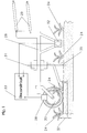
- it is in a device frame together with the Sensor technology for the detection of crops guided past the row of plants ( Figure 1).
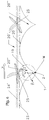
- the basic idea of the invention is the use of a cycloid trajectory Editing across the row. Points that roll with a line that circular disc are connected, run relative to the straight line Cycloid orbits (Figure 3). The circle on which the disc rolls is the rolling circle.
- the processing device has a rotating one Tool carrier, whose axis of rotation is perpendicular to the ground and which in Device frame in a longitudinal movement past the row.
- a fictitious rolling circle (Radius ⁇ ) that does not match any of the tool carriers Circular contours must coincide and a fictional straight line that forms the rolling circle Current pole touches M and runs parallel to the row of plants.
- the cycloid Path shape of a point, e.g. of a tool on the tool carrier is from depending on its distance from the fictitious rolling circle and forms accordingly different, characteristic way from (Figure 3).
- the Tool is a chopping tool in one embodiment
- the Tool path chopped while the concave arches on one side of the Cycloid track or the gusset on the other side are left blank.
- the crops that cannot be chopped stand For example, the crops that cannot be chopped stand.
- a cycloid arch spans the length of the rolling circle circumference, i.e. of the Roll circle circumference corresponds to the chopping distance. So it can with such Processing device for all rows of plants processing across the row be carried out in which the crops at a distance of Roll circle circumference stand.
- the rolling circle circumference is given dimensions of tool carrier and tool by changing the angle and / or To influence the longitudinal speed. A change in the rolling circle results in in this case also a change in the shape of the web.
- the drive and the Tool holder coupled to the tool cooxially by a clutch.
- the tool has a rotation axis that is perpendicular to the ground constant contact with the ground.
- the tool runs on one with the clutch closed cycloidal machining path.
- the clutch is disconnected, the tool unlocked. It doesn't turn anymore but turns itself through Drag effect of the ground contact parallel to the row of plants and no longer works across the row ( Figure 10).
- the clutch is closed, there is another Chipping on the cycloidal orbit, with the clutch only meaningfully remains open long until it is ensured that the machining movement Crop no longer affected.
- the processing distance, the scope of the rolling circle is extended in this way.
- the smallest possible Extending the machining distance depends on the smallest switching angle the clutch.
- the rolling circle is chosen so that it is the smallest required Plant distance corresponds to this distance and practically all larger ones Distances can be edited. Compared to suspending systems, this is a significant advantage.
- the clutch If one forms the clutch as a safety clutch, then the Tool carriers are unlocked when an obstacle occurs. In this case, the control system must ensure that the clutch first switches on again if no crop is hit.
- Figure 8 drives in an embodiment according to claims 1 and 3 a rotor disc in which the tool carrier outside the axis of rotation of the Rotor, but is mounted parallel to it. In the machining position, one connects Clutch clutch rotor and tool carrier rotatably, the tool radial to the outside. The tool runs in this position on a cycloid Track an edit. The tool has due to the perpendicular to Ground-oriented axis of rotation constant contact with the ground.
- processing such as chopping
- the non-rotatable connection of the tool carrier and the rotor is released via the coupling.
- the axis of the tool carrier on the rotor describes a cycloid path according to FIG. 6, which no longer extends into the row.
- Tool carriers and tools can move freely about their axis of rotation and are kept away from the crops by the drag effect of the soil. A chopping movement across the row does not take place in this case. Again, it is of great advantage according to the invention that the processing element itself controls ".
- a renewed coupling of the rotor and tool carrier is then intended according to the invention take place when the tool carrier automatically, without dragging additional control measures, in a radial position to the rotor and thus in the Processing position is placed.
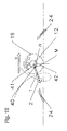
- This, for the dynamic stress of the System favorable position ( Figure 12) is once per revolution of the rotor reached. It is sensible to open the clutch in this position as well.
- the processing distance of this processing device corresponds to the respective one Roll circle circumference or whole multiples thereof.
- Fig. 1 shows the side view and the top view of a device frame 28 for a Machining direction for targeted machining across the row.
- the device frame is on one side via a parallelogram guide 29 on an equipment rack supported and on the other side by a height-adjustable support wheel 30.
- the processing unit 31 takes the device frame, the sensor system 32 for locating the Useful plants 24 and the control unit 33 for controlling the Processing device 31.
- the device frame is in the direction of the Velocity v along the crop plants 24 of the plant row 24 'through the the hatched area symbolizing the range of a row of plants 24 ' is shown.
- the tool carrier 1 with the tool 2 rotates with the Angular velocity ⁇ about the axis of rotation of the processing device 31.
- the Machining depth 37 is determined by the height setting of the support wheel 30.
- the sensor system 32 detects the position of the plants 24 and passes the information on to the Control unit 33 of the processing unit further. With the support wheel 30 is one Angle measuring device 38 connected to the assignment of plant position Sensor and processing position enabled or implemented.
- FIG. 3 and 4 shows a Cycloid "20 when the tool is on the rolling circle
- Fig. 5 shows one elongated cycloids "21 with a tool position outside the rolling circle
- FIG. 6 shows, when the tool is positioned within the rolling circle shortened cycloid "22.
- machining devices 31, the tool paths of which are 2 cycloids 20, 21, 22, can be used ideally for machining across the row.
- Extended cycloids "21 (FIG. 5) are important here.
- the shape and the width of the loop 26 of these cycloid tracks 21 depend on the distance between the tool 2 and the rolling circle 19. The distance can be ideally adapted to the machining task.
- the machining distance 27 is determined by the circumference of the rolling circle 19.
- the rolling circle 19 is therefore of crucial importance for the shape of the machining path, its dimensions depend on the forward speed v and the angular speed ⁇ , both variables determine one fictional "Roll réelle 19, which at a corresponding fictional "rolling line 23 rolls.
- the rolling line 23 runs parallel to the plant kingdom 24 ', but it does not have to be in the middle of the plant kingdoms 24 ', but something to the plant row 24 be shifted, such as Fig. 3 shows.
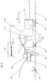
- Figure 7 shows the basic structure of a processing device according to claim 1.
- the tool carrier 1 with the tool 2 is mounted in the housing 3 and can via the clutch 4 and 11 with the drive motor 5 coaxially become.
- the two disks of the clutch are serrated 11, with on only one pair of teeth is arranged on the motor side.
- the serrated washers are compressed in operation by the spring 6 so that the required Torque can be transmitted.
- Should be the next one Machining process to be performed at a later time so opens due to a switching signal of the hydraulic cylinder 7 via the shift linkage 8 and the shift fork 9 the clutch so that the tool carrier in its storage 10th can rotate freely while the engine continues to run. Due to the drag effect of the At the bottom, the tool carrier is forced into a path according to FIG. 10.
- the Tool carrier can be connected to the drive again.
- the Hydraulic cylinder 7 opened and the spring 6 presses the two coupling halves together.
- the clutch can also be used as Safety clutch are executed.
- the helix angle of the toothing 11 and the stiffness of the spring 6 determine the torque at which the Coupling halves are pushed apart when the tool 2 in front of one Obstacle drives. It may be useful in some cases instead of not driven tool 2, for example, opposite the tool carrier 1 rotating or swinging driven tool on the tool holder 1 to arrange. As a result, a larger machining area is achieved.
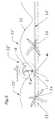
- Fig. 8 shows a processing device according to claims 1 and 3, in which the Tool carrier 1 is mounted 40 on a rotor 12 outside the rotor axis 13.
- the rotor and drive motor 5 are firmly coupled and run continuously.
- the clutch consists of Cam gear 14 and spring-loaded ratchet 15.
- a hydraulic cylinder 16 moves, due to a Control signal, a switching element 17 on a slide 18 in the web of Pawl 15 and releases the torsionally rigid connection of the rotor and tool carrier.
- the tool holder can then rotate freely in its storage on the rotor, but is due to the drag effect of the ground in a track corresponding to Figure 6 forced. It rotates once around its own during a rotor revolution Axis.
- the switching element 17 is no longer after a rotor revolution in the path of the pawl, because of a corresponding control signal Hydraulic cylinder 16 is reset, so tool carrier and rotor again firmly coupled and a new machining cycle begins.
- the clutch 14 and 15 as a safety clutch be formed.
- Fig. 10 shows how the tool path is formed when the Clutch 4 and 11 of the processing device according to FIG. 7 is opened.
- Tool carrier 1 and tool 2 are due to the drag effect of the Soil that the tool in the direction of the longitudinal movement v 39 on the Plant 24 of the plant row 24 'is passed.
- After closing the Clutch clutch moves the tool back on the cycloid Tool path 21.
- Fig. 11 shows the situation in a processing device according to Fig. 8 when the Coupling 14 and 15 the non-rotatable connection of the rotor and tool carrier has solved.
- the bearing point 40 in the rotor moves on a shortened cycloid 22 and drags the tool carrier due to the ground contact. It lies in everyone Place tangent to the shortened cycloid and becomes the 24 on the plant Plant row 24 'passed.
- FIG. 12 relates to a processing device according to FIG. 8 and shows for the case that the clutch 14 and 15 is open, a position of the rotor 12 and Tool carrier 1, in which the connecting line 41 of the bearing axis 40 and Rotor axis 13 a right angle ⁇ with the connecting line 42 of Form the instantaneous pole M and the bearing axis 40.
- Relative speed of the bearing axis 40 with respect to the ground on the Rotor axis 13 directed and the tool holder 1 is due to Drag effect in a radial position to the rotor 12. It is therefore automatic, placed in the radial machining position solely by the drag effect. If a new machining cycle is to begin, the clutch 14 and 15 snap back into this position.
Landscapes
- Life Sciences & Earth Sciences (AREA)
- Engineering & Computer Science (AREA)
- Mechanical Engineering (AREA)
- Soil Sciences (AREA)
- Environmental Sciences (AREA)
- Finish Polishing, Edge Sharpening, And Grinding By Specific Grinding Devices (AREA)
Applications Claiming Priority (2)
| Application Number | Priority Date | Filing Date | Title |
|---|---|---|---|
| DE1997150130 DE19750130A1 (de) | 1997-11-13 | 1997-11-13 | Bearbeitungseinrichtung zur gezielten Bearbeitung quer zur Reihe |
| DE19750130 | 1997-11-13 |
Publications (1)
| Publication Number | Publication Date |
|---|---|
| EP0916243A1 true EP0916243A1 (fr) | 1999-05-19 |
Family
ID=7848507
Family Applications (1)
| Application Number | Title | Priority Date | Filing Date |
|---|---|---|---|
| EP98121348A Withdrawn EP0916243A1 (fr) | 1997-11-13 | 1998-11-10 | Dispositif de travail pour travail visé à travers d'une rangée |
Country Status (2)
| Country | Link |
|---|---|
| EP (1) | EP0916243A1 (fr) |
| DE (1) | DE19750130A1 (fr) |
Cited By (8)
| Publication number | Priority date | Publication date | Assignee | Title |
|---|---|---|---|---|
| FR2851880A1 (fr) * | 2003-03-04 | 2004-09-10 | Campes Jacques Villa | Dispositif pour limiter la hauteur d'une herse pour proteger la recolte et les pieds de vigne, en deplacant le moteur hydraulique vers l'interieur du rang |
| FR2938400A1 (fr) * | 2008-11-14 | 2010-05-21 | Sarl Ferrand | Equipement pour travaux agricoles au pied des vignes |
| CN104541619A (zh) * | 2014-12-24 | 2015-04-29 | 新昌县捷马农机科技有限公司 | 一种中耕机用工作轴总成 |
| RU177760U1 (ru) * | 2017-09-05 | 2018-03-12 | Федеральное государственное бюджетное научное учреждение "Южно-Уральский научно-исследовательский институт садоводства и картофелеводства" | Приспособление для межкустовой обработки почвы |
| EP3123847B1 (fr) * | 2015-07-30 | 2019-05-08 | CNH Industrial Kutno sp. z o.o. | Lame basculante pour bineuse |
| EP3123846B1 (fr) * | 2015-07-30 | 2019-05-08 | CNH Industrial Kutno sp. z o.o. | Lame active pour bineuse |
| EP3569045A1 (fr) * | 2018-05-15 | 2019-11-20 | Deere & Company | Procédé et machine pour la culture de plantes dans un champ |
| WO2022248172A1 (fr) * | 2021-05-28 | 2022-12-01 | Rath Jun Engelbert | Dispositif de culture de sol |
Families Citing this family (1)
| Publication number | Priority date | Publication date | Assignee | Title |
|---|---|---|---|---|
| DE102023124221A1 (de) * | 2023-09-08 | 2025-03-13 | Amazonen-Werke H. Dreyer SE & Co. KG | Bodenbearbeitungsgerät |
Citations (14)
| Publication number | Priority date | Publication date | Assignee | Title |
|---|---|---|---|---|
| FR623842A (fr) * | 1926-08-09 | 1927-07-01 | Perfectionnements aux machines agricoles, telles que les charrues vigneronnes | |
| US1912706A (en) * | 1930-12-06 | 1933-06-06 | J W Culbertson | Agricultural implement |
| AT173887B (de) | 1951-09-18 | 1953-02-10 | Ernest Wimmer | Hackmaschine zum Lichten (Vereinzeln) von Pflanzenreihen |
| US3530944A (en) * | 1969-09-30 | 1970-09-29 | Perry W Spell | Agricultral implement |
| AU445984B2 (en) * | 1970-01-21 | 1974-02-20 | Hutchinson Loxley | Arow crop cultivator |
| DE2424096A1 (de) | 1974-05-17 | 1975-11-20 | Linde Ag | Verfahren und vorrichtung zur beseitigung und vernichtung von pflanzen |
| DE3916852C1 (fr) | 1989-05-24 | 1990-03-15 | Clemens Und Co Kg, 5560 Wittlich, De | |
| DE9300093U1 (de) | 1993-01-07 | 1993-03-18 | Heidtmann, Helmut, 7500 Karlsruhe | Einrichtung zur Bodenbearbeitung |
| WO1993009660A1 (fr) | 1991-11-21 | 1993-05-27 | Jan Moerk Hansen | Procede et appareil d'elimination des mauvaises herbes des cultures disposees en rangees |
| FR2687532A1 (fr) | 1992-02-25 | 1993-08-27 | Joseph Martelot | Appareil de binage mecanique inter plants. |
| DE4205231C2 (de) | 1992-02-21 | 1994-05-19 | Clemens & Co Gmbh | An ein landwirtschaftliches Fahrzeug od.dgl. anbaubare Vorrichtung zur mechanischen Unkrautbeseitigung |
| DE4411080A1 (de) | 1994-03-30 | 1995-10-05 | Andreas Hilker | Bearbeitungsmaschine für Reihenkulturen |
| DE4302198C2 (de) | 1993-01-27 | 1996-02-22 | Lorenz Luetkemeyer | Verfahren und Gerät zur Unkrautbekämpfung bei Kulturpflanzen, insbesondere Mais |
| DE4339329C2 (de) | 1993-11-19 | 1996-05-30 | Holzapfel Klaus Dipl Ing Fh | Vorrichtung zur gezielten Vernichtung bzw. Eindämmung von Unkraut |
-
1997
- 1997-11-13 DE DE1997150130 patent/DE19750130A1/de not_active Withdrawn
-
1998
- 1998-11-10 EP EP98121348A patent/EP0916243A1/fr not_active Withdrawn
Patent Citations (14)
| Publication number | Priority date | Publication date | Assignee | Title |
|---|---|---|---|---|
| FR623842A (fr) * | 1926-08-09 | 1927-07-01 | Perfectionnements aux machines agricoles, telles que les charrues vigneronnes | |
| US1912706A (en) * | 1930-12-06 | 1933-06-06 | J W Culbertson | Agricultural implement |
| AT173887B (de) | 1951-09-18 | 1953-02-10 | Ernest Wimmer | Hackmaschine zum Lichten (Vereinzeln) von Pflanzenreihen |
| US3530944A (en) * | 1969-09-30 | 1970-09-29 | Perry W Spell | Agricultral implement |
| AU445984B2 (en) * | 1970-01-21 | 1974-02-20 | Hutchinson Loxley | Arow crop cultivator |
| DE2424096A1 (de) | 1974-05-17 | 1975-11-20 | Linde Ag | Verfahren und vorrichtung zur beseitigung und vernichtung von pflanzen |
| DE3916852C1 (fr) | 1989-05-24 | 1990-03-15 | Clemens Und Co Kg, 5560 Wittlich, De | |
| WO1993009660A1 (fr) | 1991-11-21 | 1993-05-27 | Jan Moerk Hansen | Procede et appareil d'elimination des mauvaises herbes des cultures disposees en rangees |
| DE4205231C2 (de) | 1992-02-21 | 1994-05-19 | Clemens & Co Gmbh | An ein landwirtschaftliches Fahrzeug od.dgl. anbaubare Vorrichtung zur mechanischen Unkrautbeseitigung |
| FR2687532A1 (fr) | 1992-02-25 | 1993-08-27 | Joseph Martelot | Appareil de binage mecanique inter plants. |
| DE9300093U1 (de) | 1993-01-07 | 1993-03-18 | Heidtmann, Helmut, 7500 Karlsruhe | Einrichtung zur Bodenbearbeitung |
| DE4302198C2 (de) | 1993-01-27 | 1996-02-22 | Lorenz Luetkemeyer | Verfahren und Gerät zur Unkrautbekämpfung bei Kulturpflanzen, insbesondere Mais |
| DE4339329C2 (de) | 1993-11-19 | 1996-05-30 | Holzapfel Klaus Dipl Ing Fh | Vorrichtung zur gezielten Vernichtung bzw. Eindämmung von Unkraut |
| DE4411080A1 (de) | 1994-03-30 | 1995-10-05 | Andreas Hilker | Bearbeitungsmaschine für Reihenkulturen |
Cited By (10)
| Publication number | Priority date | Publication date | Assignee | Title |
|---|---|---|---|---|
| FR2851880A1 (fr) * | 2003-03-04 | 2004-09-10 | Campes Jacques Villa | Dispositif pour limiter la hauteur d'une herse pour proteger la recolte et les pieds de vigne, en deplacant le moteur hydraulique vers l'interieur du rang |
| WO2004080154A3 (fr) * | 2003-03-04 | 2004-11-11 | Jacques Villa-Campes | Dispositif pour travailler le sol entre des pieds de vigne ou analogue |
| FR2938400A1 (fr) * | 2008-11-14 | 2010-05-21 | Sarl Ferrand | Equipement pour travaux agricoles au pied des vignes |
| CN104541619A (zh) * | 2014-12-24 | 2015-04-29 | 新昌县捷马农机科技有限公司 | 一种中耕机用工作轴总成 |
| EP3123847B1 (fr) * | 2015-07-30 | 2019-05-08 | CNH Industrial Kutno sp. z o.o. | Lame basculante pour bineuse |
| EP3123846B1 (fr) * | 2015-07-30 | 2019-05-08 | CNH Industrial Kutno sp. z o.o. | Lame active pour bineuse |
| RU177760U1 (ru) * | 2017-09-05 | 2018-03-12 | Федеральное государственное бюджетное научное учреждение "Южно-Уральский научно-исследовательский институт садоводства и картофелеводства" | Приспособление для межкустовой обработки почвы |
| EP3569045A1 (fr) * | 2018-05-15 | 2019-11-20 | Deere & Company | Procédé et machine pour la culture de plantes dans un champ |
| US11134608B2 (en) | 2018-05-15 | 2021-10-05 | Deere & Company | Method and machine for plant cultivation on a field |
| WO2022248172A1 (fr) * | 2021-05-28 | 2022-12-01 | Rath Jun Engelbert | Dispositif de culture de sol |
Also Published As
| Publication number | Publication date |
|---|---|
| DE19750130A1 (de) | 1999-05-20 |
Similar Documents
| Publication | Publication Date | Title |
|---|---|---|
| EP3610712B1 (fr) | Dispositif de traitement transversal agricole | |
| CH620333A5 (fr) | ||
| EP0916243A1 (fr) | Dispositif de travail pour travail visé à travers d'une rangée | |
| DE3873440T2 (de) | Fahrzeug fuer gartenarbeiten sowie landwirtschaftliche arbeiten. | |
| DE2941293C2 (fr) | ||
| LU503190B1 (de) | Bodenbearbeitungsgerät | |
| EP1505862B1 (fr) | Appareil de travail du sol | |
| EP0140989B1 (fr) | Machine pour le travail du sol | |
| DE2858680C2 (fr) | ||
| EP0765595A1 (fr) | Appareil faucheur | |
| DE2924671C2 (fr) | ||
| EP0464374A1 (fr) | Système d'entraînement | |
| DE68904246T2 (de) | Landmaschine mit mindestens einem waehrend der arbeit angetriebenen rechrad. | |
| DE1582411B1 (de) | Maehmaschine mit Messerscheiben | |
| EP1348329A1 (fr) | Machine de travail avec au moins un outil entraíne par moteur et un frein arrêtant l'outil | |
| DE3304853C2 (de) | Feldhäcksler | |
| EP4342277A1 (fr) | Semoir et procédé de distribution de semences | |
| CH630225A5 (de) | Kreiselegge. | |
| EP3549421B1 (fr) | Planteuse | |
| DE898104C (de) | Ausgleichgetriebe | |
| DE866747C (de) | Wechselgetriebe | |
| DE69412756T2 (de) | Heuwerbungsmaschine | |
| DE3330745A1 (de) | Vorrichtung zur landwirtschaftlichen bodenbearbeitung | |
| DE3222503A1 (de) | Stockraeumgeraet | |
| DE19717522C2 (de) | Aktor für die mechanische Beikrautregulierung innerhalb der Reihen von Reihenkulturpflanzen |
Legal Events
| Date | Code | Title | Description |
|---|---|---|---|
| PUAI | Public reference made under article 153(3) epc to a published international application that has entered the european phase |
Free format text: ORIGINAL CODE: 0009012 |
|
| AK | Designated contracting states |
Kind code of ref document: A1 Designated state(s): AT BE CH DE DK ES FR GB LI NL |
|
| AX | Request for extension of the european patent |
Free format text: AL;LT;LV;MK;RO;SI |
|
| 17P | Request for examination filed |
Effective date: 19991019 |
|
| AKX | Designation fees paid |
Free format text: AT BE CH DE DK ES FR GB LI NL |
|
| GRAG | Despatch of communication of intention to grant |
Free format text: ORIGINAL CODE: EPIDOS AGRA |
|
| STAA | Information on the status of an ep patent application or granted ep patent |
Free format text: STATUS: THE APPLICATION HAS BEEN WITHDRAWN |
|
| 17Q | First examination report despatched |
Effective date: 20011211 |
|
| 18W | Application withdrawn |
Withdrawal date: 20011207 |