EP0916284A2 - Höhenverstellbarer Arbeitstisch - Google Patents
Höhenverstellbarer Arbeitstisch Download PDFInfo
- Publication number
- EP0916284A2 EP0916284A2 EP98118120A EP98118120A EP0916284A2 EP 0916284 A2 EP0916284 A2 EP 0916284A2 EP 98118120 A EP98118120 A EP 98118120A EP 98118120 A EP98118120 A EP 98118120A EP 0916284 A2 EP0916284 A2 EP 0916284A2
- Authority
- EP
- European Patent Office
- Prior art keywords
- work table
- table according
- tube
- tension member
- worktop
- Prior art date
- Legal status (The legal status is an assumption and is not a legal conclusion. Google has not performed a legal analysis and makes no representation as to the accuracy of the status listed.)
- Withdrawn
Links
- 230000001419 dependent effect Effects 0.000 description 1
- 230000004048 modification Effects 0.000 description 1
- 238000012986 modification Methods 0.000 description 1
Images

Classifications
-
- A—HUMAN NECESSITIES
- A47—FURNITURE; DOMESTIC ARTICLES OR APPLIANCES; COFFEE MILLS; SPICE MILLS; SUCTION CLEANERS IN GENERAL
- A47B—TABLES; DESKS; OFFICE FURNITURE; CABINETS; DRAWERS; GENERAL DETAILS OF FURNITURE
- A47B9/00—Tables with tops of variable height
- A47B9/12—Tables with tops of variable height with flexible height-adjusting means, e.g. rope, chain
-
- A—HUMAN NECESSITIES
- A47—FURNITURE; DOMESTIC ARTICLES OR APPLIANCES; COFFEE MILLS; SPICE MILLS; SUCTION CLEANERS IN GENERAL
- A47B—TABLES; DESKS; OFFICE FURNITURE; CABINETS; DRAWERS; GENERAL DETAILS OF FURNITURE
- A47B13/00—Details of tables or desks
- A47B13/08—Table tops; Rims therefor
- A47B13/10—Tops characterised by shape, other than circular or rectangular
Definitions
- the invention relates to a height-adjustable work table, consisting of one of at least three at a distance arranged from each other, variable in length via a common drive Support legs for holding a worktop, where each support leg consists of an outer tube and at least one there is displaceable inner tube.
- the invention is therefore based on the object of a height-adjustable To design the work table so that it also at a complicated shape of the work surface at its height, for example between 680 and 820 mm evenly and in particular can be easily adjusted.
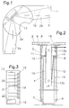
- Fig. 1 of the drawing is an example as a desk Serving work table 1 shown, the worktop 2 is composed of three parts and one angled Has shape.
- the worktop 2 consists of a Middle part 2a and two side parts running at an angle to each other 2 B. 1 of the drawing can also be seen that the worktop 2 over a total of eight support legs 3rd supported on the floor. Below the middle part 2a of the worktop 2 there are four support legs 3, during each Side part 2b at its outer end on two support legs 3 lies on. All support legs 3 are completely identical and each separately attached below the worktop 2. A frame-like connection between the individual Support legs 3 are not available.
- Each support leg 3 consists of an outer tube 4 and an inner tube 5, which is axially displaceable via guide rings 6 is guided in the outer tube 4.
- the inner tube is supported 5 from a screwable foot 7 on the ground.
- this screwable foot 7 does not serve the altitude to change the worktop 2, but to be precise horizontal adjustment of the worktop 2, i.e. with these Feet 7 of a table can compensate for unevenness in the floor become.
- the outer tube 4 is connected to a plate 9 via a ring 8, over which the support leg 3 exclusively on the worktop 2 is attached.
- the inner tube 5 is at its in that Outer tube 4 projecting, upper end closed by a cap 10, which is provided with an opening 11. Through this Opening 11 protrudes an elongated frame 12 which with its is attached to the upper end of the plate 9.
- two deflection rollers 13a, 13b are now provided, which are at a distance are each supported at the ends of the frame 12.
- the deflection roller 13a is referred to as the upper deflection roller, while the pulley 13b is the lower pulley.
- All eight support legs 3 of the work table 2 are now as shown of Figure 2 explained, trained.
- the tension members 15 of all eight support legs 3 are guided to a pulling unit 17 which indicated in FIG. 1 and shown enlarged in FIG. 3 is.
- This train unit 17 consists of a support plate 18, which are screwed onto the underside of the worktop 2 can.
- This drum 20 has a groove 21 for each tension member 15, which can be helical and, for example extends over two turns. In the grooves 21 the ends of the tension members 15 are attached evenly aligned. Now the drum 20 is rotated in the direction in which the tension cables 15 are tensioned, this inevitably leads to a even extension of all support legs 3 and thus too lifting the worktop 2. In contrast, the tension members 15 subsided over the drum 20, this leads to a Lowering the worktop 2.
- the drum 20 only has one indicated drive 22, either from a hand actuable crank or is electrically formed. It must however, always be sure that the tension members 15 in the respective height of the worktop 2 are secured, i.e. there has to be a kind of self-locking that excludes that the worktop 2 by its own weight down can move. This may only be possible via the drive 22 be.
- This train unit 17 also exists from a support plate 18 on the underside of the worktop 2 is attached.
- This support plate 18 also carries eight deflection rollers 19, in two rows and slightly against each other are staggered or stored.
- the axes of the pulleys 19 run perpendicular to the support plate 18 and thus also perpendicular to the worktop 2.
- Each guide roller 19 is used for guiding and deflecting a tension member designed as a rope 15.
- tension members 15 is one end - as in the embodiment of Figure 2 - in the support leg 3 at Point 14 attached to cap 10 while the other end of each Tension member 15 on a common for all tension members 15
- Pull plate 23 is clamped in a precisely predetermined position. This position is very easy by pulling on the respective one Tension member 15 adjustable so that all tension members 15 Extend all support legs 3 simultaneously and evenly shorten and thus an even raising or lowering of all Worktops 2a, 2b, 2c is ensured.
- any one can largely Drive can be used.
- the tension plate 23 via a piston-cylinder unit 25 moves, which can be acted upon pneumatically or hydraulically. It however, you can also use a spindle that is manually, for example via a crank, or electrically, for example about a motor that is turned.
- the entire train unit 17 is advantageously down through a not shown Plate covered.
Landscapes
- Workshop Equipment, Work Benches, Supports, Or Storage Means (AREA)
Abstract
Description
- Fig. 1
- eine Draufsicht auf die Arbeitsplatte eines Arbeitstisches gemäß der Erfindung,
- Fig. 2
- einen Schnitt durch ein Stützbein des Arbeitstisches der Fig. 1
- Fig. 3
- eine vergrößerte Darstellung einer Zugeinheit des Arbeitstisches gemäß Fig. 1. und
- Fig. 4
- eine andere Ausgestaltung der Zugeinheit.
Claims (9)
- Höhenverstellbarer Arbeitstisch, bestehend aus einem aus mindestens drei mit Abstand voneinander angeordneten, über einen gemeinsamen Antrieb längenveränderbaren Stützbeinen zur Aufnahme einer Arbeitsplatte, wobei jedes Stützbein aus einem Außenrohr und mindestens einem relativ dazu verschiebbaren Innenrohr besteht,
dadurch gekennzeichnet,
daß das Außenrohr (4) und das Innenrohr (5) jedes Stützbeines(3)über jeweils ein Zugglied (15) in ihrer Länge vergrößerbar sind und daß das Zugglied (15) jedes Stützbeines (3) über mindestens eine Umlenkrolle (13a, 13b) an eine gemeinsame, von dem Antrieb (22) beaufschlagbare Zugeinheit (17) angeschlossen ist. - Arbeitstisch nach Anspruch 1,
dadurch gekennzeichnet,
daß der Antrieb (22), die Zugeinheit (17) und zumindest ein Teil der Umlenkrollen (19) auf einer unterhalb der Arbeitsplatte (2) befestigbaren Tragplatte (19) angeordnet sind. - Arbeitstisch nach Anspruch 1 oder 2,
dadurch gekennzeichnet,
daß die Zugeinheit (17) als verschiebbare Zugplatte (23) ausgebildet ist. - Arbeitstisch nach Anspruch 3,
dadurch gekennzeichnet,
daß die Zugplatte (23) als Klemmleiste ausgebildet ist. - Arbeitstisch nach mindestens einem der Ansprüche 1 bis 3,
dadurch gekennzeichnet,
daß der Zugplatte (23) ein mechanischer, elektromechanischer, pneumatischer oder hydraulischer Antrieb zugeordnet ist. - Arbeitstisch nach Anspruch 1 oder 2,
dadurch gekennzeichnet,
däß die Zugeinheit als Trommel (20) ausgebildet ist. - Arbeitstisch nach Anspruch 1,
dadurch gekennzeichnet,
daß die Trommel (20) für jedes Zugglied (15) mindestens eine umlaufende Rille (21) aufweist. - Arbeitstisch nach mindestens einem der Ansprüche 1 bis 7,
dadurch gekennzeichnet,
daß das verschiebbare Rohr (4) jedes Stützbeines (3) zwei in axialer Richtung des Rohres (4) mit festen Abstand voneinander angeordnete Umlenkrollen (13a, 13b) für das Zugglied (15) aufweist, von denen sich die untere Umlenkrolle (13b) ständig innerhalb des ortsfesten Rohres (5) befindet und das freie Ende des Zuggliedes (15) im oberen Bereich des ortsfesten Rohres (4) befestigt ist. - Arbeitstisch nach Anspruch 8,
dadurch gekennzeichnet,
daß die beiden Umlenkrollen (13a, 13b) in einem im verschiebbaren Rohr (4) befestigten und in das ortsfeste Rohr (5) ragenden Rahmen (12) drehbar gelagert sind.
Applications Claiming Priority (4)
| Application Number | Priority Date | Filing Date | Title |
|---|---|---|---|
| DE29719881U | 1997-11-08 | ||
| DE29719881U DE29719881U1 (de) | 1997-11-08 | 1997-11-08 | Höhenverstellbarer Arbeitstisch |
| DE29816169U | 1998-09-09 | ||
| DE29816169U DE29816169U1 (de) | 1997-11-08 | 1998-09-09 | Höhenverstellbarer Arbeitstisch |
Publications (2)
| Publication Number | Publication Date |
|---|---|
| EP0916284A2 true EP0916284A2 (de) | 1999-05-19 |
| EP0916284A3 EP0916284A3 (de) | 2000-05-31 |
Family
ID=26060885
Family Applications (1)
| Application Number | Title | Priority Date | Filing Date |
|---|---|---|---|
| EP98118120A Withdrawn EP0916284A3 (de) | 1997-11-08 | 1998-09-24 | Höhenverstellbarer Arbeitstisch |
Country Status (1)
| Country | Link |
|---|---|
| EP (1) | EP0916284A3 (de) |
Cited By (3)
| Publication number | Priority date | Publication date | Assignee | Title |
|---|---|---|---|---|
| EP2967210A4 (de) * | 2013-08-12 | 2016-11-02 | Dirtt Environmental Solutions | Wandmontierte vorrichtungen, systeme und verfahren zur selektiven positionierung von objekten |
| US11261600B2 (en) | 2017-05-19 | 2022-03-01 | Dirtt Environmental Solutions Ltd. | Systems and methods for selectively positioning wall-mounted devices |
| US11957242B2 (en) | 2019-03-20 | 2024-04-16 | Dirtt Environmental Solutions Ltd. | Height adjusting and leveling worksurface cantilever |
Family Cites Families (2)
| Publication number | Priority date | Publication date | Assignee | Title |
|---|---|---|---|---|
| FR1603374A (de) * | 1968-09-30 | 1971-04-13 | ||
| AU629100B2 (en) * | 1990-02-15 | 1992-09-24 | Payco Products Pty Ltd | Adjustable height work station |
-
1998
- 1998-09-24 EP EP98118120A patent/EP0916284A3/de not_active Withdrawn
Cited By (3)
| Publication number | Priority date | Publication date | Assignee | Title |
|---|---|---|---|---|
| EP2967210A4 (de) * | 2013-08-12 | 2016-11-02 | Dirtt Environmental Solutions | Wandmontierte vorrichtungen, systeme und verfahren zur selektiven positionierung von objekten |
| US11261600B2 (en) | 2017-05-19 | 2022-03-01 | Dirtt Environmental Solutions Ltd. | Systems and methods for selectively positioning wall-mounted devices |
| US11957242B2 (en) | 2019-03-20 | 2024-04-16 | Dirtt Environmental Solutions Ltd. | Height adjusting and leveling worksurface cantilever |
Also Published As
| Publication number | Publication date |
|---|---|
| EP0916284A3 (de) | 2000-05-31 |
Similar Documents
| Publication | Publication Date | Title |
|---|---|---|
| EP0074019A2 (de) | Überwachungspult | |
| EP0094376A1 (de) | Anordnung mit zwei gegeneinander ver- und einstellbaren Arbeitsplatten zum Tragen von Datenverarbeitungsgeräten | |
| EP0296400A1 (de) | Tisch, insbesondere für Bildschirmarbeitsplätze | |
| DE29822188U1 (de) | Höhenverstellbarer Arbeitstisch | |
| DE19749494A1 (de) | Höhenverstellbarer Arbeitstisch | |
| EP0916284A2 (de) | Höhenverstellbarer Arbeitstisch | |
| EP0324899B1 (de) | Badewanneneinsatz | |
| DE69117297T2 (de) | Kupplung eines fussbodenkehrgerätes mit einem stangenähnlichen teil zum führen besagten gerätes | |
| EP1584264B1 (de) | Höhenverstellbarer Antrieb, insbesondere für Möbel | |
| EP0645105A1 (de) | Tisch und Tischsystem | |
| DE29816169U1 (de) | Höhenverstellbarer Arbeitstisch | |
| EP0242811B1 (de) | An einer senkrechten Wand montierbares Schrank- und/oder Tischmöbel | |
| DE4442719C2 (de) | Orthopädischer Lattenrost | |
| DE4227844C2 (de) | Höhenverstellvorrichtung für Arbeitsplatten | |
| DE19517656C2 (de) | Hebe- und Senkvorrichtung für Möbelelemente | |
| EP0004875B1 (de) | Hebe- und Senkvorrichtung für ein Möbelstück, insbesondere einen Tisch | |
| DE19626854B4 (de) | Traggestell für einen höhenverstellbaren Tisch | |
| DE20017803U1 (de) | Stufenweise längenverstellbares Tischbein | |
| DE202005021004U1 (de) | Höhenverstellbarer Antrieb, insbesondere für Möbel | |
| DE29909336U1 (de) | Höhenverstellbares Gestell für ein Möbel | |
| DE202023107248U1 (de) | Untergestell für einen Arbeits- oder Montagetisch | |
| DE19642592C2 (de) | Höhenverstellbarer Tisch | |
| DE4018733C1 (en) | Office desk with height adjustable desk top - has U=shaped frame, whose shanks are vertically and laterally guided | |
| DE29617926U1 (de) | Ausfahrbarer Fuß für einen höhenverstellbaren Tisch | |
| DE7716983U1 (de) | Blockierbare hubvorrichtung zum stufenlosen verstellen von stuhlsitzen, tischplatten o.dgl. |
Legal Events
| Date | Code | Title | Description |
|---|---|---|---|
| PUAI | Public reference made under article 153(3) epc to a published international application that has entered the european phase |
Free format text: ORIGINAL CODE: 0009012 |
|
| AK | Designated contracting states |
Kind code of ref document: A2 Designated state(s): AT BE CH CY DE DK ES FI FR GB GR IE IT LI LU MC NL PT SE |
|
| AX | Request for extension of the european patent |
Free format text: AL;LT;LV;MK;RO;SI |
|
| PUAL | Search report despatched |
Free format text: ORIGINAL CODE: 0009013 |
|
| AK | Designated contracting states |
Kind code of ref document: A3 Designated state(s): AT BE CH CY DE DK ES FI FR GB GR IE IT LI LU MC NL PT SE |
|
| AX | Request for extension of the european patent |
Free format text: AL;LT;LV;MK;RO;SI |
|
| STAA | Information on the status of an ep patent application or granted ep patent |
Free format text: STATUS: THE APPLICATION HAS BEEN WITHDRAWN |
|
| 18W | Application withdrawn |
Withdrawal date: 20000805 |