EP0916447A2 - Méthode et dispositif pour l'alignement d'une pièce sur une table d'une machine-outil - Google Patents
Méthode et dispositif pour l'alignement d'une pièce sur une table d'une machine-outil Download PDFInfo
- Publication number
- EP0916447A2 EP0916447A2 EP98121842A EP98121842A EP0916447A2 EP 0916447 A2 EP0916447 A2 EP 0916447A2 EP 98121842 A EP98121842 A EP 98121842A EP 98121842 A EP98121842 A EP 98121842A EP 0916447 A2 EP0916447 A2 EP 0916447A2
- Authority
- EP
- European Patent Office
- Prior art keywords
- fixture
- workpiece
- pack
- along
- coordinate axes
- Prior art date
- Legal status (The legal status is an assumption and is not a legal conclusion. Google has not performed a legal analysis and makes no representation as to the accuracy of the status listed.)
- Withdrawn
Links
Images




Classifications
-
- B—PERFORMING OPERATIONS; TRANSPORTING
- B23—MACHINE TOOLS; METAL-WORKING NOT OTHERWISE PROVIDED FOR
- B23Q—DETAILS, COMPONENTS, OR ACCESSORIES FOR MACHINE TOOLS, e.g. ARRANGEMENTS FOR COPYING OR CONTROLLING; MACHINE TOOLS IN GENERAL CHARACTERISED BY THE CONSTRUCTION OF PARTICULAR DETAILS OR COMPONENTS; COMBINATIONS OR ASSOCIATIONS OF METAL-WORKING MACHINES, NOT DIRECTED TO A PARTICULAR RESULT
- B23Q3/00—Devices holding, supporting, or positioning work or tools, of a kind normally removable from the machine
- B23Q3/18—Devices holding, supporting, or positioning work or tools, of a kind normally removable from the machine for positioning only
- B23Q3/186—Aligning devices
-
- G—PHYSICS
- G05—CONTROLLING; REGULATING
- G05B—CONTROL OR REGULATING SYSTEMS IN GENERAL; FUNCTIONAL ELEMENTS OF SUCH SYSTEMS; MONITORING OR TESTING ARRANGEMENTS FOR SUCH SYSTEMS OR ELEMENTS
- G05B19/00—Program-control systems
- G05B19/02—Program-control systems electric
- G05B19/18—Numerical control [NC], i.e. automatically operating machines, in particular machine tools, e.g. in a manufacturing environment, so as to execute positioning, movement or co-ordinated operations by means of program data in numerical form
- G05B19/402—Numerical control [NC], i.e. automatically operating machines, in particular machine tools, e.g. in a manufacturing environment, so as to execute positioning, movement or co-ordinated operations by means of program data in numerical form characterised by control arrangements for positioning, e.g. centring a tool relative to a hole in the workpiece, additional detection means to correct position
-
- H—ELECTRICITY
- H05—ELECTRIC TECHNIQUES NOT OTHERWISE PROVIDED FOR
- H05K—PRINTED CIRCUITS; CASINGS OR CONSTRUCTIONAL DETAILS OF ELECTRIC APPARATUS; MANUFACTURE OF ASSEMBLAGES OF ELECTRICAL COMPONENTS
- H05K3/00—Apparatus or processes for manufacturing printed circuits
- H05K3/0008—Apparatus or processes for manufacturing printed circuits for aligning or positioning of tools relative to the circuit board
-
- H—ELECTRICITY
- H05—ELECTRIC TECHNIQUES NOT OTHERWISE PROVIDED FOR
- H05K—PRINTED CIRCUITS; CASINGS OR CONSTRUCTIONAL DETAILS OF ELECTRIC APPARATUS; MANUFACTURE OF ASSEMBLAGES OF ELECTRICAL COMPONENTS
- H05K1/00—Printed circuits
- H05K1/02—Details
- H05K1/0266—Marks, test patterns or identification means
- H05K1/0269—Marks, test patterns or identification means for visual or optical inspection
-
- H—ELECTRICITY
- H05—ELECTRIC TECHNIQUES NOT OTHERWISE PROVIDED FOR
- H05K—PRINTED CIRCUITS; CASINGS OR CONSTRUCTIONAL DETAILS OF ELECTRIC APPARATUS; MANUFACTURE OF ASSEMBLAGES OF ELECTRICAL COMPONENTS
- H05K2201/00—Indexing scheme relating to printed circuits covered by H05K1/00
- H05K2201/09—Shape and layout
- H05K2201/09818—Shape or layout details not covered by a single group of H05K2201/09009 - H05K2201/09809
- H05K2201/09918—Optically detected marks used for aligning tool relative to the PCB, e.g. for mounting of components
-
- H—ELECTRICITY
- H05—ELECTRIC TECHNIQUES NOT OTHERWISE PROVIDED FOR
- H05K—PRINTED CIRCUITS; CASINGS OR CONSTRUCTIONAL DETAILS OF ELECTRIC APPARATUS; MANUFACTURE OF ASSEMBLAGES OF ELECTRICAL COMPONENTS
- H05K3/00—Apparatus or processes for manufacturing printed circuits
- H05K3/0011—Working of insulating substrates or insulating layers
- H05K3/0044—Mechanical working of the substrate, e.g. drilling or punching
- H05K3/0047—Drilling of holes
-
- Y—GENERAL TAGGING OF NEW TECHNOLOGICAL DEVELOPMENTS; GENERAL TAGGING OF CROSS-SECTIONAL TECHNOLOGIES SPANNING OVER SEVERAL SECTIONS OF THE IPC; TECHNICAL SUBJECTS COVERED BY FORMER USPC CROSS-REFERENCE ART COLLECTIONS [XRACs] AND DIGESTS
- Y10—TECHNICAL SUBJECTS COVERED BY FORMER USPC
- Y10T—TECHNICAL SUBJECTS COVERED BY FORMER US CLASSIFICATION
- Y10T408/00—Cutting by use of rotating axially moving tool
- Y10T408/03—Processes
-
- Y—GENERAL TAGGING OF NEW TECHNOLOGICAL DEVELOPMENTS; GENERAL TAGGING OF CROSS-SECTIONAL TECHNOLOGIES SPANNING OVER SEVERAL SECTIONS OF THE IPC; TECHNICAL SUBJECTS COVERED BY FORMER USPC CROSS-REFERENCE ART COLLECTIONS [XRACs] AND DIGESTS
- Y10—TECHNICAL SUBJECTS COVERED BY FORMER USPC
- Y10T—TECHNICAL SUBJECTS COVERED BY FORMER US CLASSIFICATION
- Y10T408/00—Cutting by use of rotating axially moving tool
- Y10T408/08—Cutting by use of rotating axially moving tool with means to regulate operation by use of templet, tape, card, or other replaceable information supply
-
- Y—GENERAL TAGGING OF NEW TECHNOLOGICAL DEVELOPMENTS; GENERAL TAGGING OF CROSS-SECTIONAL TECHNOLOGIES SPANNING OVER SEVERAL SECTIONS OF THE IPC; TECHNICAL SUBJECTS COVERED BY FORMER USPC CROSS-REFERENCE ART COLLECTIONS [XRACs] AND DIGESTS
- Y10—TECHNICAL SUBJECTS COVERED BY FORMER USPC
- Y10T—TECHNICAL SUBJECTS COVERED BY FORMER US CLASSIFICATION
- Y10T408/00—Cutting by use of rotating axially moving tool
- Y10T408/21—Cutting by use of rotating axially moving tool with signal, indicator, illuminator or optical means
-
- Y—GENERAL TAGGING OF NEW TECHNOLOGICAL DEVELOPMENTS; GENERAL TAGGING OF CROSS-SECTIONAL TECHNOLOGIES SPANNING OVER SEVERAL SECTIONS OF THE IPC; TECHNICAL SUBJECTS COVERED BY FORMER USPC CROSS-REFERENCE ART COLLECTIONS [XRACs] AND DIGESTS
- Y10—TECHNICAL SUBJECTS COVERED BY FORMER USPC
- Y10T—TECHNICAL SUBJECTS COVERED BY FORMER US CLASSIFICATION
- Y10T408/00—Cutting by use of rotating axially moving tool
- Y10T408/52—Cutting by use of rotating axially moving tool with work advancing or guiding means
-
- Y—GENERAL TAGGING OF NEW TECHNOLOGICAL DEVELOPMENTS; GENERAL TAGGING OF CROSS-SECTIONAL TECHNOLOGIES SPANNING OVER SEVERAL SECTIONS OF THE IPC; TECHNICAL SUBJECTS COVERED BY FORMER USPC CROSS-REFERENCE ART COLLECTIONS [XRACs] AND DIGESTS
- Y10—TECHNICAL SUBJECTS COVERED BY FORMER USPC
- Y10T—TECHNICAL SUBJECTS COVERED BY FORMER US CLASSIFICATION
- Y10T408/00—Cutting by use of rotating axially moving tool
- Y10T408/55—Cutting by use of rotating axially moving tool with work-engaging structure other than Tool or tool-support
- Y10T408/561—Having tool-opposing, work-engaging surface
- Y10T408/5617—Laterally adjustable surface
-
- Y—GENERAL TAGGING OF NEW TECHNOLOGICAL DEVELOPMENTS; GENERAL TAGGING OF CROSS-SECTIONAL TECHNOLOGIES SPANNING OVER SEVERAL SECTIONS OF THE IPC; TECHNICAL SUBJECTS COVERED BY FORMER USPC CROSS-REFERENCE ART COLLECTIONS [XRACs] AND DIGESTS
- Y10—TECHNICAL SUBJECTS COVERED BY FORMER USPC
- Y10T—TECHNICAL SUBJECTS COVERED BY FORMER US CLASSIFICATION
- Y10T409/00—Gear cutting, milling, or planing
- Y10T409/30—Milling
- Y10T409/30084—Milling with regulation of operation by templet, card, or other replaceable information supply
- Y10T409/300896—Milling with regulation of operation by templet, card, or other replaceable information supply with sensing of numerical information and regulation without mechanical connection between sensing means and regulated means [i.e., numerical control]
-
- Y—GENERAL TAGGING OF NEW TECHNOLOGICAL DEVELOPMENTS; GENERAL TAGGING OF CROSS-SECTIONAL TECHNOLOGIES SPANNING OVER SEVERAL SECTIONS OF THE IPC; TECHNICAL SUBJECTS COVERED BY FORMER USPC CROSS-REFERENCE ART COLLECTIONS [XRACs] AND DIGESTS
- Y10—TECHNICAL SUBJECTS COVERED BY FORMER USPC
- Y10T—TECHNICAL SUBJECTS COVERED BY FORMER US CLASSIFICATION
- Y10T409/00—Gear cutting, milling, or planing
- Y10T409/30—Milling
- Y10T409/303752—Process
-
- Y—GENERAL TAGGING OF NEW TECHNOLOGICAL DEVELOPMENTS; GENERAL TAGGING OF CROSS-SECTIONAL TECHNOLOGIES SPANNING OVER SEVERAL SECTIONS OF THE IPC; TECHNICAL SUBJECTS COVERED BY FORMER USPC CROSS-REFERENCE ART COLLECTIONS [XRACs] AND DIGESTS
- Y10—TECHNICAL SUBJECTS COVERED BY FORMER USPC
- Y10T—TECHNICAL SUBJECTS COVERED BY FORMER US CLASSIFICATION
- Y10T409/00—Gear cutting, milling, or planing
- Y10T409/30—Milling
- Y10T409/30616—Milling with means to precisely reposition work
-
- Y—GENERAL TAGGING OF NEW TECHNOLOGICAL DEVELOPMENTS; GENERAL TAGGING OF CROSS-SECTIONAL TECHNOLOGIES SPANNING OVER SEVERAL SECTIONS OF THE IPC; TECHNICAL SUBJECTS COVERED BY FORMER USPC CROSS-REFERENCE ART COLLECTIONS [XRACs] AND DIGESTS
- Y10—TECHNICAL SUBJECTS COVERED BY FORMER USPC
- Y10T—TECHNICAL SUBJECTS COVERED BY FORMER US CLASSIFICATION
- Y10T83/00—Cutting
- Y10T83/647—With means to convey work relative to tool station
- Y10T83/654—With work-constraining means on work conveyor [i.e., "work-carrier"]
- Y10T83/6568—With additional work-locating means on work-carrier
Definitions
- the present invention relates to a method and relative device for automatically aligning a workpiece, in particular a pack of printed circuit boards, on a machine tool table.
- each pack features a pair of pins projecting from one face of the pack, and which are fitted inside seats on a clamping fixture fitted to the table.
- the fixture comprises a locating member for clamping one of the pins, and a pair of bars for gripping the other pin.
- Machining printed circuits calls for a high degree of precision.
- each hole drilled on a drilling machine is about 0.5 mm in diameter and must be centered exactly on the respective circuit pad, which may be about 0.6 mm in diameter.
- the circuit must be positioned up to one micron, and the same degree of precision must be guaranteed over the entire surface of the circuit, which is normally rectangular with sides measuring many centimeters in length.
- the positioning precision of the pack clamping fixture depends on how accurately the fixture and the fixture connection to the table are machined, and on how accurately the two pins are fitted to the pack. And, since the drilling position is determined by the machine on the basis of two coordinate axes referred to the table, the coordinate axes of the drilling positions must coincide with those of the table for the pack to be positioned accurately.
- a method of automatically aligning a workpiece on a table of a machine tool wherein the workpiece is fitted to a clamping fixture carried by said table and is machined by a machining head; said head and said table being movable with respect to each other along two coordinate axes; and the method being characterized by comprising the steps of:
- a device for automatically aligning the workpiece on the table of the machine tool wherein the workpiece is fitted to said fixture by means of clamping means movable on said fixture by means of electric motors; control means being provided to so control said motors as to align said workpiece in a predetermined position.
- the workpiece is defined by a pack of printed circuit boards, and comprises two locating pins which are fitted to said fixture by means of a locating member for one of said pins, and by two bars movable towards each other to grip the other of said pins; said electric motors driving two actuators for moving said locating member along two coordinate X, Y axes, and a third actuator for moving one of said bars along one of said X, Y axes.
- the locating member is advantageously carried by a slide traveling along one of said X, Y axes; said slide being guided by a shift member moved along a first surface inclined with respect to said X, Y axes; a first of said bars being moved along a second surface inclined with respect to said X, Y axes; said inclined surfaces producing a component of movement of said locating member and of said first bar along the other of said X, Y axes.
- Number 1 in Figure 1 indicates as a whole a pack of printed circuit boards 2 as arranged for machining, which normally comprises drilling and milling.
- Pack 1 is substantially rectangular with a short side m and a long side M, and comprises an auxiliary bottom board 3 and an auxiliary cover board 4.
- Boards 2-4 are connected to one another by a pair of cylindrical locating pins 5 and 6, which are located along the center line A of pack 1, at two edges 7 parallel to short side m, and project a given length from the bottom face of auxiliary bottom board 3. As pack 1 may vary in size within certain limits, the distance between pins 5 and 6 varies according to the size of boards 2.
- number 8 indicates as a whole a machine tool comprising a number of machining heads 9, each having a tool-holder spindle 10; heads 9 are arranged in two rows on a common carriage 11 moved along a coordinate axis X by a numerically controlled servomotor (not shown); machine 8 also comprises a worktable 12 moved along a coordinate axis Y by a further numerically controlled servomotor (not shown); and each spindle 10 is movable vertically along a vertical axis Z, e.g. for drilling, by a third numerically controlled servomotor 15.
- Table 12 carries a number of fixtures 13, each for clamping a pack 1 for machining; fixtures 13 are arranged in two rows and associated with machining heads 9; and each fixture 13 ( Figure 3) comprises two straight parallel bars 14 and 16, which are made of extremely hard material, are machined accurately, and are carried by two coplanar plates 17 and 18.
- Bars 14 and 16 form a gap 19 in which are inserted pins 5 and 6 of pack 1, which is indicated by the dash line in Figure 3.
- the transverse dimensions of bars 14, 16 and gap 19 are enlarged for the sake of clarity.
- Plates 17 and 18 are fitted to table 12 in any known manner, and preferably so that bars 14 and 16 extend parallel to the X axis, as shown in Figure 2.
- Plate 17 comprises a locating member defined by a block 21 ( Figure 3) having a V-shaped seat 20 for receiving pin 5.
- Bar 16 is longer than bar 14, so as to also face block 21, and is movable parallel to itself towards fixed bar 14 and block 21 to clamp pins 5 and 6 of pack 1 onto fixture 13. More specifically, bar 16 is activated by a tubular container 22 made of elastomeric material, and which is deformed by compressed air to so move bar 16 as to clamp pin 5 against seat 20 and pin 6 against bar 14.
- block 21 is adjustable on plate 17 in two perpendicular directions. More specifically, block 21 is fitted to plate 17 by means of a plate 23 (see also Figure 5), two surfaces of which carry a pair of prismatic cross-shaped guides 24 and 25 respectively engaging a groove 26 formed in plate 17 and perpendicular to bar 14, and a groove 27 formed in block 21 and parallel to bar 14.
- Block 21 carries a nut screw 28 engaging a screw 29 connected to the shaft of a first reversible electric step motor 31 carried on an appendix 32 of plate 23.
- Plate 23 comprises a portion 33 having an inclined rib 34 engaging an inclined groove 36 formed in a further block 37; and block 37 comprises a rib 38 engaging a groove 39 formed in plate 17 and parallel to bar 14, and carries a further nut screw 41 engaging a screw 42 connected to the shaft of a second reversible electric step motor 43 carried by an appendix 44 of plate 17.
- Bar 14 is adjustable on plate 17 in a direction perpendicular to itself. More specifically, bar 14 is provided underneath with a pair of guides 46 parallel to the Y axis and engaging a corresponding pair of grooves (not shown) formed in plate 17; bar 14 comprises an appendix 47, which in turn is provided underneath with an inclined rib 48 engaging a corresponding inclined groove formed in a block 51; and block 51 carries a nut screw 52 engaging a screw 53 connected to the shaft of a third reversible electric step motor 54 carried by a further appendix 56 of plate 17.
- Each pack 1 of boards for drilling is provided with two locating elements defined by two holes 57 and 58 ( Figure 1), which are associated with, and located adjacent to and the same distance from, pins 5 and 6, so that the line joining the centers of holes 57 and 58 is parallel to the center line A of pack 1.
- Each machining head 9 in the front row ( Figure 2) carries an optoelectronic sensor defined by a television camera 59 for determining the real position of each hole 57, 58 when this is brought within the optical field of the camera.
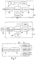
- Each camera 59 is connected to a corresponding image-processing logic circuit 61 ( Figure 6); the four circuits 61 are connected to a camera bus 62 interfacing with a logic control circuit 63 for controlling the device; and control circuit 63 interfaces with a motor bus 64 to which are connected a number of logic control circuits 66, each for controlling the three motors 31, 43, 54 of each fixture 13. In the case of the Figure 2 machine, only four control circuits 66 are provided.
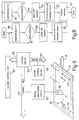
- each image-processing circuit 61 comprises an image digitization block 67, which is connected to a processor 68 connected to a RAM memory 69 and controlled by a program recorded in an EPROM memory 71; circuit 61 also comprises a serial interface 72 for connection to bus 62 (see also Figure 6); and block 67, controlled by processor 68, determines the presence of hole 57, 58, and receives and converts the read data from camera 59 into numeric data.
- processor 68 determines the center of the sensed hole 57, 58 and the dimensions of the real hole position along the X and Y axes; and, by comparison with the reference hole position represented by the position of table 12 and that of carriage 11, the components of the distance between the real hole position and the reference position are determined and recorded in RAM 69.
- Control circuit 66 comprises a microprocessor 73 connected to bus 64 via a serial interface 74, and a set of three known controllers 76, 77, 78 for driving respective motors 31, 43, 54;
- control circuit 63 comprises a processor 79 connected to a RAM memory 81 and controlled by a program recorded in an EPROM memory 82;
- circuit 61 comprises an interface 83 for connection to bus 62, an interface 84 for connection to bus 64, and an interface 86 for connection to a numeric control unit 87 of the machine.
- Packs 1 ( Figure 1) complete with holes 57 and 58 are first placed on fixtures 13 ( Figure 2) and compressed air is fed into containers 22 so that each pack 1 is clamped by bar 16 with pin 5 inside V-shaped seat 20 of block 21 and with pin 6 clamped against bar 14.
- Numeric control unit 87 ( Figures 2 and 6) then moves table 12 along the Y axis to bring holes 57, 58 of packs 1 in the front row of fixtures 13 into the plane of cameras 59, and moves carriage 11 along the X axis to align each camera 59 vertically with the desired or reference position of the respective hole 57 adjacent to pin 5 (operation 88 in Figure 8).
- Circuit 87 then enables control circuit 63 to control the aligning operation.
- Circuit 63 first enables circuits 61 sequentially to receive and digitize the signals read by cameras 59 (operation 89) and to define and memorize in each RAM 69 the error components along the X and Y axes, i.e. the components of the distance between the real position of hole 57 and the reference position (operation 90).
- Unit 87 then moves carriage 11 along the X axis to align cameras 59 with holes 58 adjacent to pins 6 (operation 91); and control circuit 63 again enables circuits 61 to receive the signals read by cameras 59 (operation 92) and to record in respective RAM 69 the Y-axis component of the distance between the real position of hole 58 and the respective reference position (operation 93).
- control circuit 63 enables processing circuits 61 sequentially to transfer the recorded X- and Y-axis components of hole 57 and the Y-axis component of hole 58 to respective control circuits 66, which are then enabled to each control the three motors 31, 43, 54 of respective fixture 13 in the front row.
- motor 43 On each of the front-row fixtures 13, motor 43, by means of block 37 (see also Figure 4), moves plate 23 according to the Y-axis component of hole 57 determined by respective circuit 61; motor 31 moves block 21 according to the respective X-axis component; and, at the same time, motor 54 moves bar 14 according to the Y-axis component of hole 58.
- Unit 87 then moves table 12 to align holes 57, 58 of packs 1 in the rear row of fixtures 13 with cameras 59 of heads 9 in the front row; machine 8 and circuits 61 are then operated by unit 87 and circuit 63 to perform operations 88-93 in Figure 8; and, finally, control circuit 63 enables control circuits 66 to operate motors 31, 43, 54 of rear-row fixtures 13 to perform operation 94.
- the aligning device therefore provides for alternately aligning packs 1 in the two rows of fixtures 13.
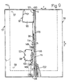
- Figures 9-14 show a pack 1 clamping and aligning fixture 113 according to a variation of the invention, and which comprises two coplanar plates 117 and 118, each having a top surface 115 for supporting pack 1.
- Fixture 113 also comprises two bars 114 and 116 carried by plates 117 and 118 and having two opposite straight parallel surfaces 95 and 96.
- Bars 114 and 116 are made of extremely hard material, are machined accurately, and have respective top surfaces flush with the top surfaces 115 of plates 117 and 118; surfaces 95 and 96 define a gap 119 in which is inserted pin 6 of pack 1, which is indicated by the dash line in Figure 9; and plates 117 and 118 are fitted to the table so that surfaces 95 and 96 of bars 114 and 116 are parallel to the X axis.
- Plate 117 comprises a locating member defined by a block 121 having a V-shaped seat 120 for receiving pin 5.
- Bar 116 is longer than bar 114, so as to also face block 121, and is movable parallel to itself towards fixed bar 114 and block 121 to clamp pins 5 and 6 of pack 1 onto fixture 113.
- bar 116 is activated by a tubular container 122 made of elastomeric material, and which is deformed by compressed air to so move bar 116 as to clamp pin 5 against seat 120 and pin 6 against bar 114.
- Both block 121 and bar 114 are fitted adjustably to plate 117.
- plate 117 comprises two cavities 97 and 98 accessible from the top, and each of which is closed by a respective plate 99, 100 fitted removably to plate 117 by means of screws 101.
- Block 121 is movable inside cavity 97 ( Figure 10) in two perpendicular directions. More specifically, block 121 is fitted by means of screws 108 inside a cavity 109 (see also Figure 11) of a substantially parallelepiped slide 123, which comprises a cavity 110 housing a pin 111 for fastening plate 99 by means of a further screw 112.
- Slide 123 comprises a flat wall 127 parallel to the X axis and therefore to surface 95, and which, by means of a return spring 126, rests against a wall 125 also parallel to surface 95.
- Wall 125 is carried by a prismatic, trapezoidal-section, intermediate shift member 133, a wall 134 of which, opposite wall 125, is inclined with respect to wall 125 by a given angle ⁇ and, by means of a second return spring 135, rests against a vertical wall 136 of cavity 97.
- Springs 126 and 135 are housed in three cavities 124, 130 and 140 respectively formed in slide 123, in intermediate member 133 and in wall 136 of cavity 97.
- Wall 136 forms a first inclined surface sloping with respect to coordinate axes X, Y, provides for guiding the movement of member 133, and is so inclined that the movement of intermediate member 133 along wall 136 itself produces a given component of movement of block 121 along the Y axis. More specifically, wall 136 and the X axis form said angle ⁇ , which may range between 5° and 10°.
- Slide 123 carries a nut screw 128 (see also Figure 12) engaging a screw 129, which is connected to the shaft of a first reversible electric motor 131 carried by an appendix 132 of intermediate member 133. Screw 129 and the shaft of motor 131 are parallel to the X axis. Intermediate member 133 carries another nut screw 141 engaging a screw 142 (see also Figure 13) connected to the shaft of a second reversible electric motor 143, which is carried by a block 144 fitted to plate 117 by means of two screws 145. Screw 142 and the shaft of motor 143 are parallel to the top surface 115 of plate 117 and to wall 136 of cavity 97.
- Bar 114 comprises a wall 147 opposite surface 95 and forming with surface 95 a predetermined angle, which may advantageously be equal to angle ⁇ .
- Bar 114 is housed in a depression 139 on plate 117 (see also Figure 14), and depression 139 has a vertical guide wall 138 forming a second inclined surface at angle ⁇ with respect to the X axis.
- Wall 147 of bar 114 rests against inclined wall 138 by means of three return springs 148 (see also Figure 9), which are inclined with respect to surface 115 of plate 117 so as to create a downward component to keep bar 114 resting against depression 139 in plate 117.
- Bar 114 is fitted by means of screws 149 with an appendix 151 of a block 150; appendix 151 is fitted with a nut screw 152 engaging a screw 153 connected to the shaft of a further reversible electric motor 154 carried by a support 155; an appendix 156 of support 155 is fitted by means of screws 157 to a shoulder 158 of cavity 98; and screw 153 and the shaft of motor 154 are parallel to top surface 115 of plate 117 and to wall 138 of depression 139.
- the Figure 9-14 device for aligning pack 1 of boards 2 operates as follows.
- the three electric motors 131, 143, 154 are controlled by circuit 66 in the same way as motors 31, 43, 54 in Figure 4.
- Pack 1 of boards 2 ( Figure 1) complete with holes 57 and 58 is first placed on fixture 113 ( Figure 9) and compressed air is fed into container 122 so that pack 1 is clamped by surface 96 of bar 116 with pin 5 inside V-shaped seat 120 of block 121 and with pin 6 clamped against surface 95 of bar 114, as on the Figure 4 fixture.
- Numeric control unit 87 ( Figure 6) then moves table 12 ( Figure 2) along the Y axis and carriage 11 of machining heads 9 along the X axis to align holes 57, 58 of pack 1 with respective optoelectronic sensor 59 and memorize the error components along the X and Y axes, i.e. the components of the distance between the real position of holes 57, 58 and the reference position, in the same way as before.
- control circuit 66 which is then enabled to control the three motors 131, 143, 154 ( Figure 10) of fixture 113.
- Motor 143 moves intermediate member 133 parallel to inclined wall 136 of cavity 97 to produce a component of movement of member 133 and of block 121 according to the recorded Y-axis component of hole 57.
- motor 131 moves slide 123 and block 121 parallel to the X axis to produce a resultant movement of block 121 equal to the respective recorded X-axis component of hole 57.
- motor 154 moves bar 114 parallel to inclined wall 138 of depression 139 to produce a component of movement of bar 114 according to the recorded Y-axis component of hole 58, so that the centers of the two holes 57 and 58 of pack 1 are aligned perfectly with the respective reference positions.
- the method of aligning a workpiece or pack 1 on respective fixture 13, 113 therefore comprises the steps of providing pack 1 with two locating elements 57, 58; fixing pack 1 to fixture 13, 113; determining the distances between the real positions of locating elements 57, 58 and two predetermined reference positions; and shifting pack 1 on fixture 13, 113 to eliminate said distances.
- the movements effected by motors 31, 43, 54 or 131, 143, 154 are normally extremely small to simply correct any positioning errors due to inevitable mechanical tolerances of the component parts.
- fixture 13, 113 and/or pins 5, 6 may be formed less accurately, thus reducing production cost.
- any mechanical inaccuracy of fixture 13, 113 and/or pins 5, 6 of packs 1 may be easily corrected, thus eliminating rejects.
- springs 126, 135 and 148 provide for dispensing with prismatic guides for block 121 and bar 114.
- motors 31, 43, 54 or 131, 143, 154 of each fixture 13 or 113 may be controlled by a corresponding control circuit 66, so that the two groups of circuits 66 are enabled alternately to receive the data memorized by circuits 61.
- Machine tool 8 may feature only one row of machining heads 9 and one row of fixtures 13, 113, in which case, only one aligning cycle is sufficient.
- the fixture 13, 113 may be applied to a machine tool having only one machining head and/or a table carrying one or more pack fixtures; and fixture 13, 113 may be oriented with gap 19, 119 parallel to the Y axis.
- Bar 16, 116 of fixture 13, 113 may be moved by a mechanism, as opposed to tubular container 22, 122; pin 5 may be clamped to block 21, 121 by a separate mechanism; one or more of motors 31, 43, 54, 131, 143, 154 may be replaced by linear actuators of any type; the means for transmitting motion to block 21, 121 and to bar 14, 114 may differ from those described; and, finally, the aligning device may be used for aligning any type of workpiece on a machine tool.
Landscapes
- Engineering & Computer Science (AREA)
- Manufacturing & Machinery (AREA)
- Microelectronics & Electronic Packaging (AREA)
- Mechanical Engineering (AREA)
- Human Computer Interaction (AREA)
- Physics & Mathematics (AREA)
- General Physics & Mathematics (AREA)
- Automation & Control Theory (AREA)
- Machine Tool Units (AREA)
- Numerical Control (AREA)
- Automatic Control Of Machine Tools (AREA)
Applications Claiming Priority (4)
| Application Number | Priority Date | Filing Date | Title |
|---|---|---|---|
| ITTO971010 | 1997-11-18 | ||
| IT001010 IT1295971B1 (it) | 1997-11-18 | 1997-11-18 | Metodo ed apparecchiatura di allineamento di un pezzo su una tavola di una macchina utensile. |
| ITTO980463 | 1998-05-29 | ||
| ITTO980463 ITTO980463A1 (it) | 1998-05-29 | 1998-05-29 | Perfezionamenti ad un dispositivo di allineamento di un pacco di pia- stre di circuiti stampati su una tavole di una macchina utensile |
Publications (2)
| Publication Number | Publication Date |
|---|---|
| EP0916447A2 true EP0916447A2 (fr) | 1999-05-19 |
| EP0916447A3 EP0916447A3 (fr) | 2000-03-22 |
Family
ID=26332366
Family Applications (1)
| Application Number | Title | Priority Date | Filing Date |
|---|---|---|---|
| EP98121842A Withdrawn EP0916447A3 (fr) | 1997-11-18 | 1998-11-17 | Méthode et dispositif pour l'alignement d'une pièce sur une table d'une machine-outil |
Country Status (3)
| Country | Link |
|---|---|
| US (2) | US6109840A (fr) |
| EP (1) | EP0916447A3 (fr) |
| JP (1) | JPH11221737A (fr) |
Cited By (4)
| Publication number | Priority date | Publication date | Assignee | Title |
|---|---|---|---|---|
| CN102114549A (zh) * | 2010-12-23 | 2011-07-06 | 北大方正集团有限公司 | 钻孔方法以及钻孔设备 |
| WO2016019177A1 (fr) * | 2014-07-31 | 2016-02-04 | Usnr, Llc | Système de positionnement de pièce à usiner dirigée de façon dynamique |
| CN112025588A (zh) * | 2020-08-03 | 2020-12-04 | 中国兵器工业集团第二一四研究所苏州研发中心 | 一种适用于双层板装配的工装夹具 |
| CN116457168A (zh) * | 2020-10-09 | 2023-07-18 | 鲍勃斯脱梅克斯股份有限公司 | 片材材料加工单元和用于评估对准的方法 |
Families Citing this family (15)
| Publication number | Priority date | Publication date | Assignee | Title |
|---|---|---|---|---|
| EP0916447A3 (fr) * | 1997-11-18 | 2000-03-22 | Borgotec Tecnologie Per L'Automazione S.p.A. | Méthode et dispositif pour l'alignement d'une pièce sur une table d'une machine-outil |
| KR100290733B1 (ko) * | 1999-05-10 | 2001-05-15 | 정문술 | 표면실장기의 인쇄회로기판 평면도 보정장치 |
| US6199290B1 (en) * | 1999-07-30 | 2001-03-13 | Excellon Automation Co. | Method and apparatus for automatic loading and registration of PCBs |
| US6612789B2 (en) * | 2000-02-25 | 2003-09-02 | Ranz Johnson | Compact disc shaping apparatus and method |
| US6438835B1 (en) * | 2000-07-19 | 2002-08-27 | Ford Global Technologies, Inc. | Method and system for manufacturing a cylinder head |
| DE102005022344B4 (de) * | 2005-05-13 | 2008-06-19 | Siemens Ag | Vorrichtung und Verfahren zur Werkstückeinmessung |
| JP4554460B2 (ja) * | 2005-07-22 | 2010-09-29 | 日立ビアメカニクス株式会社 | 穴明け加工方法 |
| CN101221045A (zh) * | 2007-01-12 | 2008-07-16 | 深圳富泰宏精密工业有限公司 | 柔性定位系统 |
| US7888664B2 (en) * | 2008-03-10 | 2011-02-15 | Eastman Kodak Company | Plate pallet alignment system |
| CN102107290B (zh) * | 2010-12-23 | 2013-07-24 | 北大方正集团有限公司 | 钻孔方法以及钻孔设备 |
| JP2013102035A (ja) * | 2011-11-08 | 2013-05-23 | Ngk Spark Plug Co Ltd | セラミック基板およびその製造方法 |
| TWI499109B (zh) * | 2013-07-08 | 2015-09-01 | Chroma Ate Inc | A method of reading and writing fixture, machine table and alignment for flexible conductive circuit board |
| US9504163B2 (en) * | 2014-08-28 | 2016-11-22 | Wojciech B. Kosmowski | Y axis beam positioning system for a PCB drilling machine |
| US10272851B2 (en) * | 2015-10-08 | 2019-04-30 | Toyota Motor Engineering & Manufacturing North America, Inc. | Vehicle emblem alignment and installation tools and methods of use |
| DE102020113134A1 (de) * | 2020-05-14 | 2021-11-18 | Skybrain Vermögensverwaltungs Gmbh | Bearbeitungsstation und Verfahren zur Bearbeitung von Werkstücken |
Family Cites Families (16)
| Publication number | Priority date | Publication date | Assignee | Title |
|---|---|---|---|---|
| US3838274A (en) * | 1973-03-30 | 1974-09-24 | Western Electric Co | Electro-optical article positioning system |
| JPS5972727A (ja) * | 1982-10-19 | 1984-04-24 | Matsushita Electric Ind Co Ltd | 位置合わせ用テ−ブル |
| US4794736A (en) * | 1985-12-27 | 1989-01-03 | Citizen Watch Co., Ltd. | Arrangement for mechanically and accurately processing a workpiece with a position detecting pattern or patterns |
| JPS62259707A (ja) * | 1986-05-06 | 1987-11-12 | Hiraoka Kogyo Kk | プリント配線板用穿孔機 |
| US4829375A (en) * | 1986-08-29 | 1989-05-09 | Multiline Technology, Inc. | Method for punching in printed circuit board laminates and related apparatus and articles of manufacture |
| US5109584A (en) * | 1989-02-28 | 1992-05-05 | Hitachi Seiko Ltd. | Printed circuit board adapter supplying apparatus and method for use in printed circuit board drilling apparatus |
| US5111406A (en) * | 1990-01-05 | 1992-05-05 | Nicolet Instrument Corporation | Method for determining drill target locations in a multilayer board panel |
| US5109854A (en) * | 1990-02-23 | 1992-05-05 | Picker International, Inc. | Roll-over aliasing suppression in undersampled images |
| ATE114262T1 (de) * | 1991-09-17 | 1994-12-15 | Siemens Nixdorf Inf Syst | Verfahren zum bohren von mehrlagenleiterplatten. |
| IT1251254B (it) * | 1991-11-08 | 1995-05-05 | Pluritec Italia | Metodo ed apparecchiatura di carico e scarico di pezzi per una macchina utensile, particolarmante per la lavorazione di piastre di circuiti stampati. |
| JPH05162035A (ja) * | 1991-12-13 | 1993-06-29 | Ono Sokki Co Ltd | XY−θ軸の微調整機構 |
| US5246316A (en) * | 1992-03-06 | 1993-09-21 | Excellon Automation | Work table orientation apparatus and method |
| EP0668606B1 (fr) * | 1994-02-07 | 1997-09-17 | Ushiodenki Kabushiki Kaisha | Dispositif de support |
| DE69514016T2 (de) * | 1994-02-28 | 2000-10-19 | Dynamotion/Abi Corp., Santa Ana | Bohrkoordinaten-Optimierung für mehrschichtige Leiterplatten |
| EP0714230A1 (fr) * | 1994-11-25 | 1996-05-29 | PLURITEC ITALIA S.p.A. | Procédé et dispositif pour charger et décharger des circuits imprimés sur un machine-outil |
| EP0916447A3 (fr) * | 1997-11-18 | 2000-03-22 | Borgotec Tecnologie Per L'Automazione S.p.A. | Méthode et dispositif pour l'alignement d'une pièce sur une table d'une machine-outil |
-
1998
- 1998-11-17 EP EP98121842A patent/EP0916447A3/fr not_active Withdrawn
- 1998-11-17 US US09/193,279 patent/US6109840A/en not_active Expired - Fee Related
- 1998-11-18 JP JP32856598A patent/JPH11221737A/ja not_active Withdrawn
-
2000
- 2000-05-26 US US09/580,304 patent/US6283681B1/en not_active Expired - Fee Related
Cited By (6)
| Publication number | Priority date | Publication date | Assignee | Title |
|---|---|---|---|---|
| CN102114549A (zh) * | 2010-12-23 | 2011-07-06 | 北大方正集团有限公司 | 钻孔方法以及钻孔设备 |
| CN102114549B (zh) * | 2010-12-23 | 2013-04-10 | 北大方正集团有限公司 | 钻孔方法以及钻孔设备 |
| WO2016019177A1 (fr) * | 2014-07-31 | 2016-02-04 | Usnr, Llc | Système de positionnement de pièce à usiner dirigée de façon dynamique |
| US9409306B2 (en) | 2014-07-31 | 2016-08-09 | Usnr, Llc | Dynamically directed workpiece positioning system |
| CN112025588A (zh) * | 2020-08-03 | 2020-12-04 | 中国兵器工业集团第二一四研究所苏州研发中心 | 一种适用于双层板装配的工装夹具 |
| CN116457168A (zh) * | 2020-10-09 | 2023-07-18 | 鲍勃斯脱梅克斯股份有限公司 | 片材材料加工单元和用于评估对准的方法 |
Also Published As
| Publication number | Publication date |
|---|---|
| JPH11221737A (ja) | 1999-08-17 |
| EP0916447A3 (fr) | 2000-03-22 |
| US6109840A (en) | 2000-08-29 |
| US6283681B1 (en) | 2001-09-04 |
Similar Documents
| Publication | Publication Date | Title |
|---|---|---|
| US6109840A (en) | Method and device for aligning a workpiece on a machine tool table | |
| US6094793A (en) | Intelligent fixture system | |
| US5246316A (en) | Work table orientation apparatus and method | |
| US5390128A (en) | Robotic processing and inspection system | |
| EP1961492B1 (fr) | Procede permettant de regler le degagement d'une buse d'applicateur de liquide et applicateur de liquide | |
| US5836068A (en) | Mobile gantry tool and method | |
| US20180217200A1 (en) | Positioning device for a parallel tester for testing printed circuit boards and parallel tester for testing printed circuit boards | |
| US20020035783A1 (en) | Method and apparatus of detecting positioning error of electric component held by suction nozzle, and method of mounting the electric component | |
| WO1993001080A1 (fr) | Procede et dispositif de montage de caisses d'automobiles et d'autres objets tridimensionnels | |
| US5996239A (en) | Method of making coordinate measurements of a workpiece on a machine tool | |
| JPS6161746A (ja) | 工具接触探査方法と切削工具の面を精密に位置ぎめする装置 | |
| CN107405748B (zh) | 机床 | |
| KR20200023746A (ko) | 하이브리드 5축 가공 및 측정 장치 | |
| CN107949457B (zh) | 设置方法以及包括设置模块的工件加工系统 | |
| US20210379709A1 (en) | Machining center and workpiece processing method | |
| JP5072743B2 (ja) | マイクロマシンおよびマイクロフライスマシン | |
| CN224083781U (zh) | 一种电路板加工设备 | |
| JP7796206B2 (ja) | 工作機械 | |
| JP7791985B2 (ja) | 工作機械 | |
| JP7603873B1 (ja) | 加工システム | |
| JPH1190555A (ja) | 工具移動式パンチプレス | |
| CN118219002A (zh) | 加工设备、控制方法和加工方法 | |
| KR20250107923A (ko) | 스핀들 교정 장치, 스핀들 교정 방법 및 인쇄 회로 기판 가공 설비 | |
| JP3977134B2 (ja) | スケールフィードバック制御系の原点確立方法 | |
| JP2572660B2 (ja) | 自動駆動型比較計測機 |
Legal Events
| Date | Code | Title | Description |
|---|---|---|---|
| PUAI | Public reference made under article 153(3) epc to a published international application that has entered the european phase |
Free format text: ORIGINAL CODE: 0009012 |
|
| AK | Designated contracting states |
Kind code of ref document: A2 Designated state(s): AT BE CH DE DK FR GB IE IT LI LU NL SE |
|
| AX | Request for extension of the european patent |
Free format text: AL;LT;LV;MK;RO;SI |
|
| PUAL | Search report despatched |
Free format text: ORIGINAL CODE: 0009013 |
|
| AK | Designated contracting states |
Kind code of ref document: A3 Designated state(s): AT BE CH CY DE DK ES FI FR GB GR IE IT LI LU MC NL PT SE |
|
| AX | Request for extension of the european patent |
Free format text: AL;LT;LV;MK;RO;SI |
|
| RIC1 | Information provided on ipc code assigned before grant |
Free format text: 7B 23Q 3/18 A, 7H 05K 13/00 B |
|
| 17P | Request for examination filed |
Effective date: 20000913 |
|
| AKX | Designation fees paid |
Free format text: AT BE CH DE DK FR GB IE IT LI LU NL SE |
|
| 17Q | First examination report despatched |
Effective date: 20020412 |
|
| GRAH | Despatch of communication of intention to grant a patent |
Free format text: ORIGINAL CODE: EPIDOS IGRA |
|
| STAA | Information on the status of an ep patent application or granted ep patent |
Free format text: STATUS: THE APPLICATION IS DEEMED TO BE WITHDRAWN |
|
| 18D | Application deemed to be withdrawn |
Effective date: 20030611 |